Note: Descriptions are shown in the official language in which they were submitted.
CA 02231527 1998-03-09
97P5516 -1- PATENT APPLICATION
HALOGEN INCANDESCENT LAMP HAVING A SOCKET
TECHNICAL FIELD
The invention relates to a halogen incandescent lamp
and <~ socket which matches it. High-voltage/medium-
voltage lamps having a socket associated therewith are
concerned. The socket can be embodied, in particular,
as an adapter for conventional sockets. For this
purpose the adapter may be equipped with, for example,
an E27/E14 screw cap, bayonet cap or the like.
BACKGROUND OF THE INVENTION
EP-A 652 610 has disclosed a low-voltage (LV)
incandescent lamp which is pinched at one end and uses
a glass cap, in which the supply leads are bent over by
180° directly on the broad sides of the pinch and bear
against them. Elastic clamp contacts arranged in the
socket permit two-point holding.
EP-A 668 639 likewise describes a socket for a low-
voltage incandescent lamp pinched at one end and having
contact springs of complicated configuration and a
plurality of wedge-shaped projections on the broad
sides of the pinch, 'the supply leads also resting on
these wedge-shaped projections. .
Finally, DE-A 28 10 402 has disclosed a socket for a
low-voltage incandescent lamp, pinched at one end, for
use with a printed circuit board, the supply leads
CA 02231527 1998-03-09
97P55:16 -2- PATENT APPLICATION
being guided away lat:eral:ly at right angles from the
pinch of the lamp for the purpose of making contact on
the painted circuit board.
Halog~=_n incandescent lamps are spreading increasingly
into many different spheres of life, for example into
the lighting of houses and flats, in vehicles, in the
industrial field etc. Their advantages are the small
overall size, the increased light yield, the good color
rendition, as well as the service life, which is longer
by comparison with conventional incandescent lamps . For
the most part, it i~; low-voltage halogen lamps, for
example with an operating voltage of 12 V or 24 V,
which are used in this case. In recent years also some
medium-voltage and high-voltage halogen incandescent
lamps have been appearing on the market.
Pin-type lamps having a pinch at one end are used in
the case of the low-voltage halogen incandescent lamps.
As holding and contact elements straight, pin-shaped
supply leads project straight out of the side of the
pinch averted from the lamp. The assigned sockets are
conse~xuently essentia=Lly characterized by two holding
openi:zgs having integrated sprang-loaded pin contacts
for the pin supply leads . Because of the low operating
volta~~e, there as no need for a safety device against
touching the live parts. These lamps are very compact.
By contrast therewith, the known medium-voltage and
high-'voltage halogen incandescent lamps which are
pinch.=d at one end preponderantly use additional outer
bulbs having a conventional medium-voltage (MV) or
high-voltage (HV) standard cap. They are even mandatory
CA 02231527 1998-03-09
97P557.6 -3- PATENT APPLICATION
in thc~ case of screw caps for safety reasons . Serving,
frequently, as connecting part between the lamp and
outer bulb, on the on~~ hand, and the standard cap, on
the other hand, is a ceramic part into which the lamp
and outer bulb are cemented. Fastening the ceramic part
to the standard cap is likewise performed, as a rule,
by cementing, bonding or crimping. To eliminate the
risk of bulb explosion. at the end of the service life,
one tc~ two fuses are connected between the supply lead
and c:ap contacts. Th.e halogen incandescent lamp is
thereby of the same external configuration as a
conventional incandescent lamp for this voltage range
(at least 80 V; typical values for MV are 100 to 120 V,
and for HV 220 to 250 V), and is also essentially
exact:~_y the same size. The reason for this is the
safet~~ requirements (shock protection in the
corresponding voltage range; anti-explosion protection)
and the stipulations, owing to the widespread
luminaires, with respect to the standard cap, as well
as tree requirement for exchangeability between the
conventional lamp and halogen incandescent lamps. HV/MV
lamps are significantly more expensive both by
comparison with the corresponding conventional
incandescent lamps and by comparison with LV halogen
incan<3escent lamps having a transformer, because of
these design features. Their market share has therefore
so far been relatively low. On the other hand, there
have not so far been any compact high-voltage/medium
volta<~e halogen incandescent lamps at all on the
market..
L,'I LI i1 I
CA 02231527 2002-07-15
97P5516 - 4 - PATENT APPLICATION
S1JMMARY OF THE INVENTION
The invention is based on the technical problem of
providing as compact as possible a system which is
S composed of a halogen incandescent lamp and socket for HV
and MV. A further object is to provide a halogen
incandescent lamp and a matching socket or a system which,
on the one hand, lead to improved environmental protection
and, on the other hand, to savings in costs.
The invention is thus based on the idea to make MV/HV
lamps which are as compact as possible in that, also in
the case of these lamps, glass caps are used. Under
specific preconditions, in this case it is even possible
without substantial safety risks to dispense with the use
of fuses for avoiding bursting of lampbulbs at the end of
the service life. This can be achieved, in particular, by
means of suitably shaped supply leads. Examples are
described in German Utility Model 91 02 566 (the supply
lead is spiraled and forms a blow-out channel in the
pinch) and in German Utility Model 296 07 132 (the supply
lead is a thin unspiraled wire with a diameter of at most
200 ~,m, in particular 130 Vim). Explicit reference is made
to these publications.
According to an embodiment of the invention, a high-
voltage/medium-voltage halogen incandescent lamp includes a
glass bulb, pinched at one end to form a glass cap, a
5 filament arranged within the glass bulb, at least one
internal supply lead that is connected to the filament and
extends into the glass cap, wherein the internal supply
lead is a thin wire with a diameter of at most 200 ~,m, and
i i ~i
CA 02231527 2002-07-15
97P5516 - 4a - PATENT APPLICATION
preferably, at most 130 Vim.
According to another embodiment according to the invention,
use is made of a halogen incandescent lamp which is pinched
at one end and designed for the medium-voltage/high-voltage
range and whose pinch is constructed as a glass cap having
two narrow sides and two broad sides. The system comprises
overall a halogen incandescent lamp pinched at one end and
an assigned socket, the lamp being a high-
CA 02231527 1998-03-09
97P55_L6 -5- PATENT APPLICATION
voltac~e/medium voltage halogen incandescent lamp having
a lamp axis, whose pinch is constructed as glass cap
having external supply leads situated essentially on
the side of the glassy cap averted from the lamp, the
sockel~ having an insertion opening for the lamp, a
mechanical holding device for holding the lamp on the
glass cap and metallic contacts for making electric
contact with the supply leads of the lamp.
The external supply leads of the lamp are bent over by
at least approximately 90°. The electric contacts of
the ~cocket in one embodiment make contact with the
supple leads in the bE~nt-over region. It has proved to
be thermally favorable when the bend of the supply lead
is arranged at a spacing from the glass cap. A
particularly stable arrangement in mechanical terms is
one in which the supply lead is guided back after the
bend ~~s far as the glass cap and, in particular, bears
again:~t the narrow side of the pinch . A high degree of
compactness can be achieved when the electrical
contacts of the socket: contact the supply leads in the
region of the free, guided-back ends thereof.
In this case the holding device cooperates with a
holding means, in mo_~t cases with a recess and/or a
projection on the glass cap in t:he manner of a latching
holde:_ .
Projecting from the g:Lass cap are supply leads of the
lamp which are situated essentially on the side of the
glass cap averted from the lamp, that is to say
esseni~ially "at the bottom", when the lampbulb with the
incandescent wire is "at the top".
CA 02231527 1998-03-09
97P55:L6 -6- PATENT APPLICATION
Furthc=_rmore, it is provided in a preferred embodiment
that, by contrast with the low-voltage halogen
incanciescent lamps and their sockets, it is not the
supply leads and assigned holding bores, but rather the
region of pinch situated "thereabove" itself which is
used as the holder contact between lamp and socket.
With the lamp mounted in the socket, the supply leads
are correspondingly situated "below" the pinch or the
mechanical holder. They li.e thus deeper in the socket
than in the case of LV systems. The glass cap and the
holder thus contribute, in accordance with the
invention, to covering the live parts. For this
purpose, essential parts of the supply leads are
arran~3ed below the pinch, while, frequently, in the
case ~~f glass cap lamps for LV operation, they are bent
dire ctly at the end face o.f the pinch towards the broad
sides thereof.
An essential point of consideration concerns the
conta~~t points between the supply leads and the
corresponding metal mating contacts of the socket.
Because the lamp is already held on the glass cap, it
is possible (by comparison with the pin-type lamps) to
confi~~ure the shape of the supply leads, which are
arranged essentially below the glass cap, and the shape
of the socket such that the contact points have a
certain spacing from t:he glass cap. As a result, there
is a marked reduction in the thermal loading of the
conta~~t points and thus of their oxidation. This
advantage also holds by comparison with the
conve:ztional standard caps described above since, owing
to tr.eir shape and solid design, the latter cause a
CA 02231527 1998-03-09
97P5516 -7- PATENT APPLICATION
comparatively very intense conduction of heat to the
contact points.
On the other hand, the possibility is thereby produced
of fitting the metal contacts in the socket at so large
a spicing that it is impossible to erroneously make
contact with LV lamps whose pin spacings are less than
6 . 3 5 :~nm .
In order to realize this, the supply leads of the lamp
are bent over by at least approximately 90° towards the
narrow sides. This bend has the effect firstly of
increasing in a simple manner the distance between the
metal contacts of the socket. As a result, a protection
is rE~alized against the inadvertent use of a low-
voltage halogen incandescent lamp with the resulting
danger of explosion. Owing to the changed contact
spacing, it is impossible with a low-voltage halogen
incan~~escent lamp having a standardized spacing between
the supply leads for simultaneous contact to be
produ~~ed with both c~~ntacts of the socket, and this
eliminates the risk of accidents.
In spite of this, in the case of the lamp itself, the
spacing between the supply leads in the pinch and
immediately in front thereof outside its end face can
be held to the standard spacing of 6.35 mm introduced
with low-voltage halogen incandescent lamps. Moreover,
this standard spacing has become established for the
halogen incandescent lamps in the high-voltage range
which are used in outer bulbs and auxiliary standard
caps. The lamps in a~:cordance with the invention can
there:Eore continue to be produced at low cost with the
CA 02231527 1998-03-09
97P551.6 -8- PATENT APPLICATION
machinery already available and then, by a simple
bending over of the supply leads, the spacing between
the contact regions and the supply leads can be
enlarged. By contrast with LV halogen incandescent
lamps,. bending over in the case of HV halogen
incandescent lamps represents no problem, since the
molybdenum wires used typically have a diameter of less
than 0.5 mm. By the bE~nding over outwards, the spacing
of the contact regions is increased by at least 10~
over LV lamps, corresponding to a spacing of the
contacts in the socket: of more than 7, preferably more
than 8, and particularly preferably more than 9 mm.
Final_Ly, a certain spring action of the supply lead is
achie~Ted by bending over, especially when the end of
the supply lead is guided back as far as the pinch. The
contact making between the supply lead and the mating
contact of the socket is thereby improved and can
there:Eore be carried out by simple touching. In this
case of a contact making by touching it is advantageous
to configure the mating contact of the socket
esseni=Tally in a flat fashion, for example, as a leaf
spring, so that it does not. hold the supply lead, while
the c~~ntact area of the supply lead is chosen to be as
large as possible in that it is more or less flat
(planed or slightly bent).
Depending on whether the contacts of the socket are
provided in the insertion direction of the lamp in
front or laterally ne~a to the supply leads, it can be
sensible in this regard to extend the bend by
conspicuously more t:~an 90°, for example 180°. In
particular, the supply lead can be bent over in a
CA 02231527 1998-03-09
97P5516 -9- PATENT APPLICATION
rounded shape, that is to say it can point back with
its free end to the glass cap. Moreover, it can be
advantageous if the supply lead bent back in such a way
is situated for the purpose of stabilization with its
end i.n a recess, for example in a groove in the narrow
side of the glass ca.p. In order to support the said
spring action, a free spacing from the glass cap should
be left in this case :in the direction of the respective
spring. For example, vhis direction is the longitudinal
direction of the lam;o when the metal mating contacts
are ~cituated in front of the supply leads, seen in the
direction of insertion of the lamp.
Alternatively or in addition, a spring action can also
be obtained by resilis~nt mating contacts of the socket.
The service life and 'the reliability of the contacts is
increased when the mating contacts on the socket side
are provided with separate springs, in particular with
helical springs. In order - possibly in addition to the
stabilization in the recess of the glass cap explained
above - to better guide the supply lead when producing
the contact between the supply lead and the mating
contact on the socket side, a guide device, for example
a shaft, can be positioned i.n front of the mating
contact of the socket, for example, by appropriately
constructing the housing of the socket.
A high degree of compactness and reliable contacting
are achieved by virtue of the fact that both the
holding and the contact making are achieved by spring
forces of resilient means which act axially or
transverse to the axi~~ .
CA 02231527 1998-03-09
97P557.6 -10- PATENT APPLICATION
The resilient means is, in particular, a single helical
spring or leaf spring which cooperates with the
electric contact such that it simultaneously ensures
both t:he holding and the electric contact making.
In another variant, the resilient means for holding is
a resilient holding clamp, while the resilient means
for contacting is a :zelical spring. In this case, a
reces:~ and a projection can be situated next to one
another on the glass cap, and the clamping spring is
designed for the purpose of engaging into the recess
beyond the projection.
In a :First embodiment, the system is designed such that
the lamp has been inserted inclined with respect to the
longitudinal direction of i.ts end position and has been
latched, rotating about an axis transverse to the
longitudinal direction of the lamp, into a latching
holder cooperating with a projection on a narrow side
of the glass cap.
In a second embodiment, the lamp is inserted in the
longit=udinal direction of its end position and is
latched, rotating about its longitudinal direction as
axis of rotation, into a latching holder cooperating
with ~~ projection on the glass cap, the latching holder
being arranged, in particular, in a cover of the
socket..
In a third embodiments, the lamp is inserted in the
longit=udinal direction of its end position, and is
thereby latched into a latching holder cooperating with
CA 02231527 1998-03-09
97P55:L6 -11- PATENT APPLICATION
a recess and/or with a projection on the glass cap or
the e:~ternal supply lead.
Fundamentally, according to one of the various
embodiments, the system can also be configured such
that the socket is constructed as an adapter having a
standard cap (screw cap or bayonet cap) for high-
volta~3e/medium-voltage lamps.
The basic concept of the socket according to the
invention for holding a high-voltage/medium-voltage
halogen incandescent :Lamp having a glass cap is based
on the following features: an insertion opening matched
to the glass cap, a mechanical holding device, suitable
for holding the lamp on the glass cap, and metallic
conta~~ts suitable for making electric contact with
supply leads of the lamp on the side of the glass cap
averted from the lamp.
This basic concept permits a clear distinction from
sockets for LV lamps, by virtue of the fact that the
spacing between the metal mating contacts is at least
7 mm wide. In the case of the LV lamp it is at least
10a s:~aller.
Advantageously the socket comprises at least two parts
having riveted or crimped joints. As a result, it is
possible to use different. material for the parts (a
material which can be subjected to high thermal loads,
for example ceramic, is more favorable on the lamp
side), on the one ha::~d, and rocketing of the springs
and contacts in the socket is made easier, on the other
hand.
~ ~ I I .I i
CA 02231527 2002-07-15
97P5516 - 12 - PATENT APPLICATION
The socket can additionally be provided with an open jacket
bulb, in particular an opal screen, W filter screen, color
filter screen, a transparent luminaire cover or an outer
bulb.
The socket is advantageously equipped with guide grooves or
guide shafts for the supply leads of the lamp, which are
arranged next to the contacts of the socket.
A suitable halogen incandescent lamp pinched at one end is
an, MV/HV halogen incandescent lamp whose pinch is
constructed as a glass cap and whose supply leads are, in
particular, bent over by at least approximately 90° such
that the supply leads are situated essentially on the side
averted from the lamp in front of the glass cap.
In particular, the lamp is equipped with a recess and/or a
projection for latching a complementary latching holder of
a socket.
The supply leads are advantageously bent over at a spacing
from the glass cap and, in particular, are guided back as
far as the glass cap. High stability and good contact
making are achieved when the ends of the bent-over supply
leads are embedded in grooves on the narrow sides of the
glass cap.
According to another embodiment of the invention, a high-
voltage/medium-voltage halogen incandescent lamp includes:
a glass bulb that is pinched at one end to form a glass
cap, where the glass cap includes two broad sides, two
narrow sides and an end face, the end face being opposite
I,,,LI fl I
CA 02231527 2002-07-15
97P5516 - 12a - PATENT APPLICATION
the bulb; a filament arranged within the glass bulb; and
35 external supply leads that are connected to the filament,
extend a predetermined distance away from the end face of
the glass cap, bend outward toward respective adjacent
narrow sides of the glass cap through an angle of
approximately 180°, and extend within grooves formed on the
40 narrow sides, wherein the external supply leads remain
substantially between planes containing the broad sides.
In a particular case, the glass cap may be formed to have a
double-T shaped cross-section on an axis parallel to the
45 bottom edge, thus providing a thinner center section and
thicker end sections, and the glass cap may be formed with
at least one of a projection and a recess on the thinner
center section for fastening the lamp into a socket.
50 The glass cap offers various design possibilities in order
to optimize the mounting and the seating in the holder of
the socket. Even a simple glass cap, with a
CA 02231527 1998-03-09
97P55:L6 -13- PATENT APPLICATION
rectangular cross-section, for example, can be gripped
strai~~ht away in a stable and secure fashion by a clamp
or a positive fit which is part of the socket.
The above possibilit_Les opened up by the invention
produce substantial advantages with regard to the
problem addressed by the invention. Thus, by comparison
with low-voltage systems it is possible to dispense
with the transformer, and this renders the luminaires
not only smaller and much more cost-effective but, with
regard to their limited service life, also more
environmentally friendly, of course. This results from
eliminating the refuse burden represented by the
transformer and by the outlay on material connected
with it. Furthermore, a possible source of defects, and
thus of a premature end to the service life of the
luminaire as a whole is eliminated. In addition, the
humming during dimmed operation, which frequently
occurs with inexpensive transformers, is avoided.
By comparison with the conventional systems for medium-
voltage and high-voltage operation, there is a
considerable reduction in the price of the halogen
lamps owing to the replacement of the conventional
standard cap by the glass cap. In addition, the outer
bulb, which has been mandatory to date in the case of
screw caps, can now be omitted. There is an analogous
reduction in the outlay on material and assembly and on
the i:~cidence of refuse.
The systems of pin-type lamps widespread in the low-
voltage range are unsuitable for the medium-voltage and
high-voltage range because of safety reasons.
CA 02231527 1998-03-09
97P5516 -14- PATENT APPLICATION
Very small lampbulbs are provided by the invention for
the medium-voltage and high-voltage range, however,
without safety risks so that extraordinarily compact
luminaire designs are rendered possible. The reason for
this is not only the reduced lamp size, but also the
possibility which is provided - essentially by the
elimination of the standard cap described - of
designing very compact lamp sockets.
With regard to the formulation of the problem for the
invention, there is a further configuration according
to the invention i:n an adapter solution to the
conventional standard caps in the medium-voltage/high-
voltage range, that is to say, for example, to the
well-established E11, E14, E26, E27, BlSd or B22d caps.
The socket according t:o the invention is then connected
to ar.. appropriate standard cap, or has an appropriate
standard cap. As a result, the system according to the
invention can in practice be retrofitted to all
luminaires with standard caps which are well-
established and in use. As a result, luminaires
operated to date with the conventional medium-
voltage/high-voltage halogen incandescent lamps or with
halogen-free incand~=_scent lamps can also be
retrofitted, with the result that the user profits from
the advantages of the halogen lighting or from the cost
advantages of the invention, and safety and
environmental protection are satisfied.
A particular advantage of the system according to the
invention is that the costs of replacement lamps will
be so low that they hardly differ any longer from the
CA 02231527 1998-03-09
97P55:L6 -15- PATENT APPLICATION
prices of convention<~l incandescent lamps. Thus, a
substantial increase in the market share of halogen
incandescent lamps is made possible. The socket/lamp
system according to tree invention even can be designed
to be so small that by contrast with conventional
incandescent lamps or conventional halogen incandescent
lamps with standard caps the design volume is reduced.
As a result, retrofitting is possible virtually in an
unlimited fashion in all luminaires.
Advani_ageous embodiments of the socket are designed in
a cernent-free fashion and the required joints are
designed to be plugged, riveted, crimpled, clamped or
similar. The freedom from cement benefits environmental
prote~~tion and, moreover, the separation of materials
is facilitated upon disposal. Moreover, the soldering
of eyelets and side c~~ntacts, which is usually carried
out with lead-containing solder in the case of HV/MV
halogen incandescent lamps is advantageously switched
to an environmentally friendly joining technology, such
as laser welding, for example. In particular, joining
rivet; in the socket can be of hollow design and serve
as screw holes or bolt holes through which the socket
is joined to the described adapter part or to a
luminaire.
Final:Ly, the socket may be provided with an integrated
screen, for example with an opal, UV filter or color
filter screen, or with a transparent luminaire cover or
with a screwed-on auxiliary protective bulb, for
examp.Le as shock protection or for aesthetic reasons.
In the last-named inst=ance, the invention can lead, in
the case of the adapter solution described, to a lamp
CA 02231527 1998-03-09
97P5516 -16- PATENT APPLICATION
which resembles the conventional medium-voltage/high-
voltage halogen incandescent lamp, but can be
dismantled and is largely reusable.
A further attractive advantage of the adapter solution
with screw cap according to the invention consists in
that it is possible b:y means of a suitable increase in
diameter of the adapter directly above the screw cap
(generally designated as overhang) for the mandatory
shock protection to be integrated into the adapter
without an outer bulb being required for this as in the
prior art. To date, this shock protection has been
realized in a very complex fashion in the case of
conventional halogen :incandescent lamps having a screw
cap by fitting an outer bulb which, in this case,
simultaneously also functions as protection against
touching the actual lampbulb.
Because it is now possible to dispense with the outer
bulb, the novel adapter solution with a suitable
diameter results in enormous cost advantages in the
case of screw cap adapters. Additional savings result
in the case of raw materials and in the production
process. Furthermore, the recyc:Lability of the products
is improved and envirc>nmental pollution is reduced.
The inherent safety is achieved by virtue of the fac t
that the overhang of the adapter now always reliably
screens the side contact in the standard cap so that it
is impossible when a};changing a lamp inadvertently to
reach live parts with the finger. By contrast, it was
possible earlier to touch live parts inadvertently in
the case .of a burst or disconnected outer bulb.
CA 02231527 1998-03-09
97P55_L6 -17- PATENT APPLICATION
Whereas a conventiona.L lamp having a diameter of the
cap which is sufficiently large for shock protection
(corresponding to the now possible overhang) would be
very expensive and therefore not competitive, in the
case of the adapter solution according to the invention
the relatively expensive adapter with sufficient
overhang, that is, large diameter, has to be purchased
only when the system is purchased for the first time.
l0 After this, the low-cost purchase of a spare lamp with
glass cap is always sufficient.
It is provided according to the invention to hold the
lamp in the socket by means of its glass cap. It is
preferred in this case to use a latching holder in the
case of which at least one recess and/or at least one
projection on the glass cap cooperates with at least
one complementary element in the socket. Particular
consideration is given in this case to snap-fit or
bayonet joints. Such a latching holder is particularly
effeci~ive when a projection and a recess are situated
next to one another on the glass cap and the latching
holde:= grips beyond the projection into the recess, in
order to hold the lamp. This has the particular
advani~age that an integral construction (preferred in
any case) of the projection or the recess on the glass
cap i.s facilitated by virtue of the fact that the
material displaced from the recess serves to build up
the projection. Thus, during production there is no
need either to remove material or to apply it, and the
latching holder can latch over a distance corresponding
to the sum of the height of the projection and the
depth of the recess.
CA 02231527 1998-03-09
97P557_6 -18- PATENT APPLICATION
In the case of all the variants of the holder and, in
particular, of the latching holders, it is preferred
for reasons of safety that the socket has an insertion
opening for the lamp which, taking account of the
possibility of easy insertion, is largely adapted to
the cross-sectional profile of the glass cap and
holder, possibly reaching up to the insertion opening.
A double-T cross-sectional profile of the pinch (and of
the glass cap formed therefrom) is preferred in this
case, which on the one hand permits good guidance in
the insertion opening and, on the other hand, permits
good stability of the glass cap. Since the glass cap is
held in accordance with the invention by the holder,
its stability is more important than in the case of
conventional halogen incandescent lamps.
Various possibilities exist for inserting the lamp and
the latching holder, of which the following are
preferred and are illustrated in more detail in the
exemp_Lary embodiments .
First:Ly, the lamp can be inserted somewhat obliquely
with respect to its final position and already be
pressed in the process against the contacts of the
sockets in order then, if appropriate against the spring
force of the socket contacts, to be guided into the
latching holder by a rotary movement about an axis
extending transverse to the longitudinal direction of
the lamp. For this purpose, at least one recess or at
least one projection is situated on at least one of the
sides of the glass cap which is lateral in the sense of
rotation, for example the narrow sides of a glass cap
CA 02231527 1998-03-09
97P5516 -19- PATENT APPLICATION
having a rectangular cross-sectional profile. In this
case, the latching can consist simply in that the
spring force of the contacts on the socket side presses
the lamp by means of one or more projections into a
recess on the socket which is laterally open for
insertion, and thus lock it therein.
Another alternative consists in a socket corresponding
to a bayonet cap, in which the direction of insertion
and t:he longitudinal direction of the lamp coincide
during insertion and _Ln the end position, and the lamp
is latched in the socket, in a fashion rotating about
its longitudinal direction, in a way similar to that
just described.
Finally, it is particularly preferred to dispense
entirely with a rotai:y movement and simply to insert
the lamp into the end position in its longitudinal
direction and latch it directly by means of the
insertion movement. A spring means (generally a snap-
action spring or leaf spring) in the socket which
cooperates with the projection/recess combination
outlined can be used, in particular, in this case.
Independently of the precise configuration of the
conta~~ts and the holder, it is preferred that the lamp
can easily be exchanged without further dismantling
measures by simply removing the lamp from the socket or
inserting it into the' socket. This only requires the
lampbulb to be gripped and moved in a fashion, that is,
resembling the case of an LV halogen incandescent lamp
having a pin cap.
CA 02231527 1998-03-09
97P557_6 -20- PATENT APPLICATION
It is pointed out as a precaution that the abov.e-
mentioned individual features explained in conjunction
with 1=he exemplary embodiments can also be essential to
the invention in other combinations or in each case per
se. 7.n particular, l.he features described here of
lamps,. sockets, or systems formed therefrom can be
applied not only to the specific field of application
of medium-voltage/hidh-voltage halogen incandescent
lamps but also to other lamps. This holds, on the one
hand, generally for halogen incandescent lamps of all
types,, but also for other lamps such as discharge
lamps,, in particular low-wattage metal halide lamps
having bulbs pinched at one end as described, for
example, in the US-PS 4 717 852.
Furthermore, it is po_Lnted out that the subject-matter
of this application, _~n particular in combination with
the subject-matter of German Utility Model 296 07 132
or of. German Utility Model 91 02 566 of the same
applicant, develops particular advantages. The teaching
disclosed there of so configuring the internal supply
lead that it acts as an inherent fuse renders possible
halogen incandescent lamps which can be operated
without separate fuse,, since they do not explode upon
failure. In the present connection, this has the
advantage that the so~~kets, adapters and/or luminaires
can be operated without fuse and that, in particular,
fitting cannot be done erroneously with regard to the
power rating of the lamp and the fuse.
CA 02231527 1998-03-09
97P55_L6 -21- PATENT APPLICATION
BRIEF DESCRIPTION OF THE DRAWINGS
The invention is to be explained in more detail below
with the aid of a plurality o.f exemplary embodiments
which are illustrated in the attached figures, in
which:
FigurE~ 1 shows a side view of a system composed of a
lamp and socket according to a first
exemplary embodiment;
Figurf~ 2 shows a view of the internal design of the
socket according to the first exemplary
embodiment;
FigurE~ 3 shows a longitudinal section according to the
section III-III in Figure 2;
Figure 4 shows a longitudinal section through a system
composed of lamp and socket according to a
second exemplary embodiment (Figure 4a) as
well as a top view of the socket from above
(Figure 4b) and from below (Figure 4d) as
well as a cross-section at the level of the
cover (Figure 4c);
Figure 5 shows two longitudinal sections rotated by
90° to each other (Figures 5a and 5b) of a
system composed of lamp and socket according
to a third exemplary embodiment;
Figure 6 shows various details of the exemplary
embodiment in accordance with Figure 5,
CA 02231527 1998-03-09
97P55__6 -22- PATENT APPLICATION
concerning the lamp (Figures 6a-c) and
concerning t:he contacts (Figures 6d-f);
FigurE~ 7 shows a fo:r the most part longitudinally
sectioned view of a system composed of lamp
and socket according to an adapter version;
Figure 8 shows a longitudinal section, rotated by 90°
with respect to Figure 7, of a further
exemplary embodiment which is modified
slightly with respect to Figure 7, and
Figure 9 shows a further exemplary embodiment,
slightly modified with respect to Figure 5.
BEST MODE FOR f~ARRYING OUT THE INVENTION
The first exemplary ernbodiment shows a tilting version
of the system according to the invention and
corresponds to the embodiment of a latching holder.
The system is particularly suitable for table lamps,
built--in furniture lurninaires or the like. To be seen
in Figures 1 to 3 is a high-voltage halogen
incandescent lamp 1 which is plugged into a socket 2
and i;s held in an opening 7 of the essentially cuboidal
sockei_ 2 by means of its glass cap 3. The socket 2 is
provided on one broad side with a riveted-on plate-
shapec~ cover 4 which has been omitted in the view
according to Figure 2 for the sake of clarity. In turn,
the cover is shown in Figure 3 on the right-hand edge
of the section orthogonal to Figure 2. The entire
extremely compact system is only 62 mm high overall,
and the diameter of the lamp is 13 mm. The socket is
CA 02231527 1998-03-09
97P551.b -23- PATENT APPLICATION
26 mm wide and 26 mm high as well as 11 mm deep. As
Figure 2 shows, the lamp has two supply leads 9, which
proj ec:t from the end :Face 8 of the pinch and are bent
over outwards in the shape of a semicircle.
It is well in evidence from Figure 3 that the lamp 1
can be inserted in an inclined fashion into the opening
7 because of the oblique upper edge 4a of the cover 4.
In this case, the supply leads 9, shown in Figure 2, of
the lamp press downwards the contacts 6 of the socket
2, wh=Lch are shaped like a bow, bent to resemble a "C"
and ara sprung in the interior of the "C" with helical
springs 11. This is possible because the contacts 6 are
guided in shafts 10, with the result that the lamp 1
can be inserted deeper under pressure. The lamp is then
tilted into the longitudinal axis A. In this process,
rotation takes place about an axis of rotation situated
horizontally in the plane of the paper in Figure 2 and
perpendicular to the plane of the paper in Figure 3, as
a result of which boss-like projections 5a on the glass
cap 3 of the lamp can be guided below a recess in a
latching holder 5b. If~ the pressure is reduced and the
lamp 1 is finally let= go, the springs 11, which are
seated on transverse webs 12 in the socket 2, press the
lamp upwards into the recess in the latching holder 5b,
and, on the one hand, the lamp is held securely and, on
the other hand, there is a secure contact between the
contacts 6 and the lower piece of the bow of the supply
leads 9 of the lamp.
Illustrated in the lower region of the figures in each
case are two cables 13 which are fastened to the
CA 02231527 1998-03-09
97P5516 -24- PATENT APPLICATION
contacts 6 by means of cable lugs, or are riveted or
welded to the contacts.
It is to be seen _Ln Figure 2 and Figure 3, in
particular, that the live parts of the socket 2,
specif=ically the contacts 6, are partly covered by the
collar_ 14 grouped around the opening 7, that is to say
the upper region of the socket 2. This collar 14 has
the latching holder 5b and closely surrounds the glass
cap 3. It is matched to the glass cap 3 as far as
possible with a slight. play. Apart from this close fit
between the glass cap 3 and insertion opening 7, only
the oblique upper edge 4, required for the inclined
insertion, of the cover 4 is to be seen, as on the
right in Figure 3.
A particularly good covering of the live parts of the
socket. is achieved by means of a second embodiment,
specii:ically a rotating version of the system according
to the invention. In this case, the glass cap of the
lamp in principle imitates a bayonet cap, see the
second exemplary embodiment shown in Figures 4a to 4d,
which corresponds to the configuration of a latching
holder. By contrast with the first, however, the
second exemplary embodiment has a greater overall
height. of the socket, with the result that it cannot be
designed quite so flat, as becomes plain from the
following. A particular advantage of this embodiment is
that t:he socket can easily be tailored to the width of
the pinch of the lamp, with the result that this width
can be chosen freely.
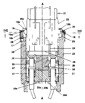
CA 02231527 1998-03-09
97P55_L6 -25- PATENT APPLICATION
Here, the socket is a hollow cylindrical body 22 made
from ceramic or steatite, in which a separate
cylindrical inner body 20 is mounted rotatably about
the longitudinal axis A. The inner body 20 comprises
two parts 20a and 20:b, which are arranged one above
another and through which two contact pins 26 extend
paral=_el to the axis A. Said pins are resiliently
mounted by means of helical springs 31 which stop
against collars 27 of the pin contacts. Starting from
its upper end face 19, the upper part 20a of the inner
body has a slot-shaped holder 33 which is matched to
the g~_ass cap of the lamp to be held.
As the longitudinal section (Figure 4a) and the top
view (Figure 4b) show, mounted on the upper end face
19, constructed as annular collar, of the socket is a
cover 18 which is made from sheet metal and has an edge
18a which is drawn down circumferentially on the
outside on the annular collar. The cover 18 is part of
a latching holder, and is fastened by crimping three
lateral depressions :L7 of the socket (respectively
spaced apart by 120°;~. The cover 18 further has an
elongated camber 16 on its surface. It comprises two
outer camber parts 16a and 16b which are separated from
one another in the middle by an aperture 16c resembling
a sector or a double fan. Furthermore, next to the
camber parts 16a, b mirror-symmetric aperture parts 16e
and 16f offset in each case by an angle of rotation of
approximately 20° with respect to the camber parts are
attached outwardly to the large aperture 16c. The shape
of the entire aperture corresponds essentially to the
cross--section of the pinch of a lamp, taking account of
an axial rotation of 20°.
CA 02231527 1998-03-09
97P551.6 -26- PATENT APPLICATION
A high-voltage halogen incandescent lamp 21 pinched at
one end and having a pinch designed as a glass cap 23
is inserted vertically from above into the hollow
cylindrical socket 22 through the aperture 16c in the
cover 18 into the holder 33 in the upper part 20a of
the inner body. Two projections 30, in the shape of a
hemisphere or boss, on the narrow sides of the glass
cap 23 of the lamp in this case fit exactly through the
aperture parts 16e and 16f (see the left-hand half of
Figure 4a and Figure 4b) and come to be situated in
bow-shaped cutouts 29 in the collar of the socket 22
(see Figure 4c). A 20° rotation of the lamp 21 about
the central axis A rotates the two projections 30 under
IS the corresponding camber parts 16a and 16b of the cover
18 (Figure 4b), as shown in the right-hand half of
Figure 4a. In this case, the entire inner part 20,
which contains the pin contacts 26 with the springs 31,
is also rotated. It i's expedien.t to limit the maximum
possible angle of rotation ~ by an end plate 20c, which
is arranged directly below the inner body 20. It has a
cutout: 20d which is similar in shape to a bow-tie and
correspondingly limits the angle of rotation ~ (see
Figure 4d).
When t:he lamp 21 is inserted into the holder 33, supply
leads 24 of the lamp, which are bent over outwards in a
semicircular shape and which are guided out of the end
face 28 of the glass bulb 23, also press against the
pin contacts 26 of the socket 22, which are spring-
loadecl by the separave helical springs 31. In this
case, the supply leads 24 are guided in groove-like
depre~;sions 32 on the floor of the holder 33. Pressing
CA 02231527 1998-03-09
97P5516 -27- PATENT APPLICATION
down the pin contacts 26 permits the bosses 30 to come
below the level of the cover 18, with the result that
the rotation can be executed until the bosses 30 are
located below the cambers 16a, 16b. When the lamp 21 is
released, the springs 31 press the lamp so high again
that the bosses 30 latch in the cambers 16a, 16b. The
lamp is releasably locked.
The following exemplary embodiments all correspond to
the Embodiment of a snap-action or plug-in version.
This embodiment is particularly preferred because in
principle it unites the advantages of the previous
exemp.Lary embodiments and can moreover be realized in a
particularly simple way and provides an extremely
compact system.
In this case, an HV la:mp/socket system having a maximum
diamel_er of 22 mm and an overall length of not more
than 51 mm (up to 60 W power) or 57 mm (up to 100 W
power;) is realized for the first time, something which
appeared out of reach up till now.
FigurE=_s 5 and 6 show the third exemplary embodiment in
cross--sectional representations rotated by 90° relative
to on~= another (Figures 5a and 5b) , as well as details
(Figu:ra 6). A high-voltage halogen incandescent lamp 41
having a pinch-sealed glass cap 43 in the shape of a
double T in cross-section can be inserted into an
insert=ion opening 47 in a socket 42 perpendicularly
from above.
The socket 42 is a round cylinder having a total height
of 17 mm and a diameter of 22 mm. It comprises a bottom
CA 02231527 1998-03-09
97P5516 -28- PATENT APPLICATION
part 42a, in the shape of a small plate, and a top part
42b w_Lth the insertion opening 47. The two parts are
riveted to one another (35). The insertion opening 47
terminates at a base part 36 and is surrounded by a
collar 37.
Fastened in the insertion opening 47 is a holding clamp
45 which is bent in a U-shaped fashion and whose two
limbs 45a are bent inwards slightly. The connecting
piece 45b connecting the limbs 45a is locked in a
connecting channel 38 on the lower end face of the base
part 36.
The 7_amp is held ::mechanically as follows : upon
insertion of the lamp, the limbs 45a of the holding
clamp (which forms a latching holder) fitted in the
insertion opening 47 latch with their rounded concavely
bent over ends 45c ove:_ a wedge-shaped projection 40 in
the broad side of the glass cap into a complementary
groove-like recess 39, on the glass cap 43, arranged
thereabove and adjacent: thereto.
Making the electric contact of the lamp is performed as
follows: in accordance with Figures 6a to 6c, two
supply leads 44 emergs~ at a spacing of 12 mm at the
lower end face of the glass cap. They comprise wires
0.5 mm thick. The latter are firstly guided outwards in
a straight line for about 4 mm, but then bent back in
the shape of a semicircle and lengthened so much that
they are guided, anti thus stabilized, in axially
parallel grooves 52 on the narrow sides 51 of the
pinch.
CA 02231527 1998-03-09
97P5516 -29- PATENT APPLICATION
Upon insertion of the lamp, the supply leads 44 push
sheet metal contacts 46 of the socket, which are
arranged below the glass cap 43, slightly outwards
radia:lly against the :Force of separate helical springs
S 53, ,end thereby produce an electric contact. The
contacts 46 have an upper lip 48 which is bent away at
right angles radially outwards on the basic body 46a.
The upper lip facilitates sliding of the contact 46 in
a cavity 49 which is provided for this purpose and is
fitted on the side in the collar 37. The springs 53,
situal_ed transverse to the axis of the lamp, are fixed
to tr.e base face 46a of the contact by means of a
bulging projection 50. The force transmission from the
supply lead 44 onto the contact 46 is facilitated by a
dent 53a, directed obliquely outwards, in the bending
region between the basic body 46a and upper lip 48.
Thus, in this embodiment the contact point between the
suppl~,r lead and socket contact is situated outside to
the side on the outer limb of the supply leads 44,
which are bent over by 180° in the shape of a
semicircle.
This type of making contact is optimized in every
respect, since the bow formed by the supply lead
creates a satisfactory spacing of the contact point
from the glass cap. Thermal problems are thereby
minim_Lzed. On the other hand, fixing the supply lead in
the groove ensures a high stability of this design. At
the same time, the bow encourages a gradually rising
transrnission of force onto the contact. upon insertion
of the lamp. Finally, a very long common contact
surface between the contact and supply lead is also
rendered possible thereby, as a result of which
CA 02231527 1998-03-09
97P55__6 -30- PATENT APPLICATION
trans__tion resistances are reduced and corrosion
problems caused by heat are avoided.
This type of design for making contact permits the
conta<:t spacing to be differentiated with respect to LV
lamps,. with the result that erroneous insertion of LV
lamps is prevented from the very first. Accidents due
to Erroneous insertion of low-voltage halogen
incandescent lamps are therefore impossible in this
l0 exemp:_ary embodiment, because latching the latching
holder_ 5 does not require a counterforce on the part of
the contacts 6 or the .springs 11.
The supply leads 44 are guided in guide shafts 55 which
are situated in the base part 36 of the upper part of
the socket 42. The lower part contains two bores for
feeder- cables 54, which are fastened to the lower end
of the contacts 46.
Figures 5a and 5b show that the insertion opening 47 in
the wade direction is matched to the dimensions of the
broad side of the pinch of the glass cap 43. It still
leave:> a sufficient space in the narrow direction for
the bent ends 45c of t:he holding clamp 45 to be sprung
out. By comparison with the first two exemplary
embodiments, the overall resu:Lt is a substantially
smaller insertion opening 47 accompanied by optimum
shock protection of the contacts 46, which otherwise
are also largely covered by their lateral arrangement.
The separate holding clamp 45 is dispensed with in a
version in accordance with Figure 9, which is
simplified and more cost-effective by contrast with
CA 02231527 1998-03-09
97P551.6 -31- PATENT APPLICATION
Figures 5/6. The mechanical holding is performed,
rather., in a similar fashion to that in the first
exemplary embodiments. It is produced by means of the
cooperation of the sheet metal contacts, moved by the
transversely situated helical springs, with suitably
shaped external supple leads. Identical components to
those in Figure 5 are provided in Figure 9 with
identical reference symbols.
In this case, the ouver part of the external supply
lead 44 (that is to say the part which adjoins the 180°
bend outside) is not bent back in a straight line
towards the narrow side of the pinch (and mounted there
in the groove 52); it additionally bulges outwards. It
IS firstly describes in the plane of the supply leads,
directly after the curvature, a bow 70 directed
outwards. The sheet. metal contact 71 has an
appropriately matched, inwardly directed bend 72 of
semicircular shape, with the result that the contact 71
resembles a question dark when seen from the side. In
the end position, the bend 72 is arranged higher than
the bow 70, with the result that it can latch behind
the bow 70. The latch region is preferably at the level
of a lateral quarter-circle-type cutout 75 in the end
of the pinch. Shear forces acting on the supply leads,
which consist of molybdenum, are minimized as a result.
Upon insertion of the lamp, the small spring-loaded
contact plate is pres~;ed outwards briefly upon passing
the bow 70. Upon reaching the end position, the bend 72
latches behind the bow 70. The transverse helical
spring 73, which presses the contact 71 from outside
again>t the supply lead 44, is now arranged at the
CA 02231527 1998-03-09
97P5516 -32- PATENT APPLICATION
level of the bow 70. Its pressure presents inadvertent
disconnection of the latching connection. In connection
with the contacts, the supply leads thus effect not
only the electric connection but also the mechanical
holding .
In order to prevent a certain play of the lamp in the
insertion opening 47, projections 74 resembling bosses
are fitted on the narrow sides of the pinch and are
1d guided in vertical guide shafts in the wall of the
insertion opening 47, and thus prevent the lamp from
tilting sideways.
Figures 7 and 8, which show two side views rotated by
90°, correspond largely to Figure 5. However, they show
two adapter versions in which, instead of a fixed
assembly of the socket in a luminaire, an adapter 56
now r.=_places the socket part. The adapter 56 has a top
part 58, which corresponds in principle to that
described in Figures 5/6. The bottom part 59, which is
fitted with a screw cap 57, is fastened to the top part
via two hollow rivets 60. A cable leading from a first
contact 61a to the side contact 62 of the screw cap is
clamped into the bottom part 59 by means of crimping,
while a second cable leads from the contact plate 63 of
the E27 cap to a second contact 61b. The remaining
components correspond to the previous exemplary
embodiment. In the embodiment of Figure 7, the bottom
part has an E14 screw cap. The overall height of the
system is 81 mm. In the embodiment of. Figure 8, the
bottom part has an E27 screw cap, and moreover an outer
bulb 65 is also slipped over the inner bulb. The outer
bulb is fastened to the bottom part 59 by means of
CA 02231527 1998-03-09
97P557_6 -33- PATENT APPLICATION
spring sheets 66. The overall height is approximately
90 mm..
It is particularly worthy of mention that the lateral
overhang 64 (2.5 mm width) at the adapter ensures shock
protection in both exemplary embodiments. It therefore
replaces the outer bulb (Figure 7) previously mandatory
or renders the outer bulb 65 a purely design feature
(Figure 8).
The bottom part of the adapter can also be provided
with a bayonet cap instead of a screw cap. Furthermore,
instead of an outer bulb it is also possible, for
example, to fasten a reflector or decorative satin-
frosted (translucent opal) glass envelope on the
adapter. In this case, a funnel-shaped, conical or
bell-:shaped opal screen is attached as an open glass
envelope 14, in a way similar to the adapter shown in
German Utility Model 92 O1 057. In this previously
known adapter system, the lamp is, however, fitted with
a conventional bayonet cap (type BlSd) and the adapter
is fitted with the corresponding mating component. The
overa7_1 length is therefore substantially greater than
in the case of the solution according to the invention.
Instead of the opal screen, it is equally conceivable
to provide an arbitrarily shaped separate glass bulb
which is detachably fastened to the socket 2, for
example screwed, in order to be able to reach the lamp.
Of course, any other auxiliary components of a lamp or
luminaire are also conceivable, for example filters,
mirrors, lenses or more such.
CA 02231527 1998-03-09
97P5516 -34- PATENT APPLICATION
The following are used as materials in the exemplary
embodiments: molybdenum for the lamp supply leads;
ceramic, preferably processed ceramic or heat-resistant
plastic, for the parts of the socket or of the adapter;
nickel-plated iron or nickel-plated copper alloy for
the rivets, spring steel for the spring of the latching
holder in the case of Figures 5 to 9; copper alloys or
nickel-plated iron for the contacts 6; and silicone-
insulated cables at the contacts 6.
In the exemplary embodiments shown in Figures 5 to 8,
the socket 2 is as~;embled as follows: the holding
spring 5 is plugged from below into the top part of the
socket 2; the cables are fastened to the contacts 6 by
IS riveting or resistance welding. The cables are inserted
with the contacts ancthe springs 11, and the bottom
part and the top part. of the socket 2 are riveted by
the rivets 12; if appropriate, the standard cap shell 8
is mounted on the bottom part and crimped.
2U
The s;~acing of the contacts 6 achieved in the exemplary
embodiments shown in Figure 5 ff. is clearly larger
than the standard spacing of LV lamps (6.3 mm). It is
at least 7 mm, preferably 9.6 mm. Of course, there is
25 also otherwise the need to provide appropriate
clearances matched to the voltage and creepage paths.