Note: Descriptions are shown in the official language in which they were submitted.
CA 02232510 2008-11-13
TECHNICAL FIELD
The invention relates to a device for absorbing electrical noise with the aid
of elements made
from a noise absorbing or noise preventing material placed around an
electrical cable.
DESCRIPTION OF THE BACKGROUND ART
It has long been known that with the aid of ferromagnetic elements it is
possible to reduce
electrical noise on the line. See U.S. Pat. No. 3,462,715, for example.
It is also known to make such ferromagnetic material elements in split form,
so that they can be
subsequently fitted to a cable. The two parts must be in contact so that the
action is effective.
This can be brought about as disclosed in EP Published App. No. 0452992 A2 by
placing the two
half-elements in a casing, whose bases have elastic pretensioning means
pressing the two
magnetic elements onto one another.
The problem to be solved by the invention is to provide a device for absorbing
electrical noise,
which has a simple construction and in which the insertion of the elements of
a noise absorbing
or noise preventing material is easy.
SUMMARY OF THE INVENTION
In the device of the present invention, two casing half-shells with the noise
preventing or
absorbing material elements located therein are fitted to an electrical cable
in which noise is to be
reduced. This can take place by folding together or assembling the two casing
half-shells.
If the two elements are subsequently inserted in the previously manufactured
casing half-shells,
fitting takes place in such a way that initially the two elements made from
the material are
inserted in the two casing half-shells and each is subsequently secured by a
respective web. The
web thereby traverses the present semicylindrical groove of the ferromagnetic
element. As a
result, the two casing half-shells can be assembled around the electrical
cable.
The interconnection of the two casing half-shells can take place by means of
snap-on devices or
in any other way, by an adhesive tape, wire or the like placed around the
outside of the casing.
1
CA 02232510 2008-11-13
In particular, in a further development, for locking the casing one casing
half-shell is provided
with a tongue having a tooth system and which cooperates with a tooth system
on the other half-
shell. As a result of the fine tooth system the casing can be locked in finely
graduated positions,
so that it is possible to compensate for tolerances in the manufacture of the
ferromagnetic
elements.
It is possible to fit such tongues and tooth systems to both longitudinal
sides or both end faces.
The tongues can in particular be so positioned that they also bring about a
reciprocal alignment
of the two casing half-shells.
The tooth systems are so chosen that they have a sawtooth configuration, to
prevent
unintentional release.
It is also possible to interconnect the two casing half-shells by a film hinge
on each longitudinal
side thereof, so that they can then be folded from the open into the closed
state and from an open
position to a closed position. Here again, a tongue and tooth system is
possible for locking the
half-shells.
For angular alignment of one of the two ferromagnetic elements, a rigid and,
in particular,
rounded projection, which preferably extends over the entire casing length.
The outside of the
ferrite element then rests on the projection and can then tilt within certain
limits about its
longitudinal axis.
According to a further development of the invention the web, which is used for
fixing the ferrite
elements, can be in the form of a semicylinder, so that in the assembled state
the webs in the two
half-shells form a closed cylinder, which completely covers the inside of the
semicylindrical
grooves of the ferrite elements. In the closed state the longitudinal edges of
the two semicylinder
webs engage on one another and consequently hold the webs in position.
For fixing the device to the electrical cable, according to the invention at
least one of the webs
forming the fixing device can have an inwardly directed projection for fixing
the cable. This
projection can have an elastic construction. It is also possible for the two
webs, particularly the
two semicylinders, to have such a projection, which is preferably centrally
positioned.
2
CA 02232510 2008-11-13
According to a further development of the invention the webs can be laterally
insertable into the
casing half-shells. It is also possible and is proposed that the web is
connected by means of a
film hinge to one end of a casing half-shell.
Further features, details and advantages can be understood from the following
description of a
preferred embodiment of the invention in which reference is made to the
drawings, which form a
part hereof and which show:
BRIEF DESCRIPTION OF THE DRAWINGS
FIG. 1 A longitudinal section view through a device according to the invention
in the
assembled state.
FIG. 2 A cross-section through the arrangement of FIG. 1 taken in the plane
indicated by line
2-2 in FIG. 1.
FIG. 3 A detail view of the lower portion of FIG. 1 with a casing half-shell
in the unfolded
state.
FIG. 4 A side view in elevation of the device corresponding to FIG. 1.
FIG. 5 A plan view of a second embodiment of the invention before the noise
absorbing
elements are inserted.
FIG. 6 A sectional view corresponding to the view of FIG. 3, but applied to
the embodiment of
FIG. 5.
FIG. 7 A cross-section through the arrangement of FIG. 5 taken in plane
indicated by line 7-7
therein.
FIG. 8 A front view in elevation of a third embodiment of the invention before
the noise
absorbing elements are inserted.
FIG. 9 A detail sectional view of a half-shell in a fourth embodiment.
FIG. 10 A plan view of a modified half-shell in a fifth embodiment.
3
CA 02232510 2008-11-13
FIG. 11 A top plan view of a web for the half-shell shown in FIG. 10.
FIG. 12 A top plan view of a half-shell in a sixth embodiment.
FIG. 13 A simplified transverse sectional view of a seventh embodiment.
FIG. 14 An enlarged detail sectional view of a locking device between two
casing halves.
DETAILED DESCRIPTION OF THE PREFERRED EMBODIMENTS
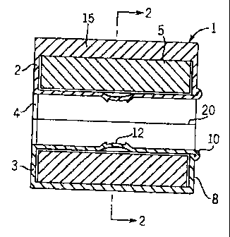
FIG. 1 shows the device proposed by the invention in the ready-to-operate
state, the electrical
cable in which the electrical noise is to be suppressed being omitted from the
drawings for a
better view of the device. The device contains a casing 1 formed from two
casing half-shells 2,
3. The two casing half-shells 2, 3 are so joined together that their open
sides rest on one another.
As a result the assembled casing has an opening 7 therethrough extending
between its two end
faces, which are aligned. A ferromagnetic element 5 is disposed in each casing
half-shell 2, 3,
the ferromagnetic element having roughly the same length as the interior of
the casing half-shell
2. The ferromagnetic element 5, hereinafter referred to as ferrite element,
has on its one side a
semicylindrical groove 6 extending over the length of the ferrite element 5.
In the assembled
state according to FIGS. 1 and 2, the two ferrite elements 5 face one another
in such a way that
the two semicylindrical grooves 6 together form a cylindrical passage. The
ferrite elements 5
further include two adjacent separating faces 7 which rest on one another. As
a result, a closed
ferrite body is formed around the passage and through it passes the electrical
cable.
Referring now to FIG. 3, a web 9 is attached to each of the two end faces 8 by
a film hinge 10.
The web 9 is in the form of a circular semicylinder or expressed otherwise as
a half-tube 11.
Roughly in the center of the longitudinal extension, a resilient projection 12
is formed in the web
9, where it projects into the channel formed by the half-tube 11 and is
provided with two
individual, small prongs 13.
The second casing half-shell 2, which in FIG. 3 is to be considered behind the
visible casing
half-shell 3, is also articulated with the aid of a film hinge 14 onto the
casing half-shell 3 and
also this second casing half-shell 2 has a web 9 articulated by means of a
film hinge 10.
4
CA 02232510 2008-11-13
In the two open half-shells 2, 3 in the position shown in FIG. 3 are inserted
the ferrite elements 5,
namely one ferrite element 5 in each half-shell, the grooves 6 being located
at the top, and
towards the open side of the half-shells 2, 3. The base of one of the two half-
shells 2 contains a
rounded projection 15 running in the longitudinal direction of the casing, as
seen above in FIG.
2, on which rests the corresponding ferrite element 5. Through a certain
amount of rolling on the
crest of the projection 15 it can also tilt somewhat. The two locking webs 9
are now folded
around until they are located in and lock in the groove 6 of the ferrite
elements 5. The casing is
then closed by folding together the two half-shells around the film hinge 14.
On the longitudinal
side of the casing opposite to the film hinge 4, the half shell 3 has a tongue
16, which has on its
inside a single tooth or a row of teeth. The tongue 16 is so dimensioned that
its inside is roughly
flush with the outside of the facing half-shell. This second half-shell,
namely the top half-shell
in FIG. 2, contains at this point a row of teeth 17, see also FIG. 4. The
teeth have a sawtooth
configuration, so that it is impossible to detach the tongue 16 without using
a tool. On folding
together the casing half-shells 2, 3 they are pressed onto one another to such
an extent that the
two ferrite elements 5 engage on one another at their separating faces 7. In
this position the
tongue 16 remains locked with respect to the tooth system 17. The tongue 16
has three webs
16a, b, c, with which it is shaped onto the casing half-shell 3, its free end
then being connected in
one piece by a cross out 18. The shaping or articulation of the tongue 16 is
immediately
alongside the edge 19 of the casing half-shell 3 facing the other casing half-
shell 2. This
prevents any resilience of the locking system.
If the device proposed by the invention is folded around an electrical cable,
then the projections
12 engage on the outside of the cable, so that the overall device is non-
positively fixed to the
cable.
When the casing is locked on the longitudinal edges 20 of the separate plane
of the webs 9
engage flat on one another.
In the illustrated embodiment the two half-shells are articulated together
with the aid of a film
hinge 14. It would also be possible to construct the two casing half-shells as
separate parts and
then bring about fixing in such a way that the casing half-shell 3 has a
tongue 16 on each of its
two longitudinal sides and the other casing half-shell has a corresponding
ratchet system 17 with
teeth. This would enable a locking of the casing in the closed state.
5
CA 02232510 2008-11-13
The embodiment shown in FIGS. 5 to 7 differs slightly from the preceding
embodiment and
consequently only the differences will be explained.
Two transversely directed webs 25 are joined to the respective casing half-
shells 22, 23, a short
distance behind respective end walls 24. The two pairs of webs 25 serve to
compensate for
tolerances during the manufacture of the elements to be inserted in the casing
half-shells 22, 23.
In this embodiment they replace the projection 15 provided in the embodiment
of FIGS. 1 to 4 on
the base of one or both half-shells.
Once again on the unilateral end walls 24 of the two half-shells 22, 23 is
attached by a film hinge
26 in each case one cross-sectionally roughly U-shaped channel 27. This
channel 27 is used for
fixing the elements and for this purpose is placed around the film hinge 26,
the terminal edge 28
facing the film hinge 26 being locked in the casing.
The base of the channel 27 has two shaped projections 29, which project into
the interior of the
channel 27 and secure the electrical cable there.
On the longitudinal side remote from the film hinges 30 linking the two casing
half-shells 22, 23,
one of the half-shells 22 has a tongue 31, which has on its inside a rib or
tooth system.
Correspondingly the facing side wall of the other casing half-shell 23 has a
rib system 32 in
sawtooth fonn, which cooperates with the rib system on the inside of the
tongue 31.
The tooth system 33 on the inside of the tongue 31 can in particular be
gathered from FIG. 6,
which shows the tongue 31 in side view. The tooth system 33 can also be seen
in FIG. 7.
FIG. 8 shows another embodiment, which has a casing comprising two casing half-
shells 34, 35.
The casing comprising the two half-shells 34, 35 is injection molded around
the noise absorbing
material elements placed in a mounting support. As a result of the shrinkage
occurring with this
manufacturing mode, the casing contracts somewhat, so that it forms a tight
fit with the elements
5. The tolerances which may arise during the manufacture of the ferrite
elements are
compensated when the casing half-shells are made in this way, so that a simple
snap hinge
closure 36 is sufficient for fixing purposes. Also in the embodiment according
to FIG. 8 the
inside of the semicylindrical groove 6 of the elements 5 can be covered by a
plastic layer, which
is manufactured during injection molding. However, this is optional.
6
CA 02232510 2008-11-13
In the case of the half-shell for housing one element made from the electrical
noise preventing or
absorbing material shown a somewhat resilient hook 42 is shaped onto a side
wa1141 and forms
in the area of its free end a barb 43. With this hook 42 the casing 40 can be
fixed to a printed
circuit board or some other component in that the hook 42 is introduced
through an opening or
breakthrough. On the opposite side wall, not shown in FIG. 9, is provided a
correspondingly
shaped, symmetrically arranged hook 42, so that fixing can take place by
merely snapping in.
The distance between the underside of the base of the half-shell 40 and the
barb 43 can be
matched to the conventional circuit board thickness.
FIGS. 10 and 11 show details of another embodiment, in which the locking teeth
45 which are
provided for locking the two half-shells 44 are located within a recess of the
longitudinal side
wall of one half-shell 44. The tongue on the other half-shell can be so shaped
that it can engage
in the recess 46. The edges of this tongue slide in the laterally constructed
grooves 47 of the
recess 46. This not only ensures a reliable guidance of the tongue on
enclosing the casing, but
also prevents an engagement behind the tongue when the casing is closed.
Once again in the end walls 49 of the half-shell 44 are formed semicircular
openings 50 for the
passage of the cable, to which the half-shells are to be fixed.
The base 48 of the half-shell has two ribs 51 running transversely to the
connecting line of the
openings 50 and which serve to compensate tolerances of the ferrite cores.
In the semicircular openings 50 of the end walls 49 are provided several
projections 52, 53. The
central projection 53 can have a type of tongue.
The front end of the transverse web 9 cooperate with the projections 52, 53
according to FIG. 11.
FIG. 11 shows such a transverse web 9, which has a similar construction to the
web 9 of the
embodiment of FIG. 3 in the form of a channel of half-tube. In the area of its
front ends it has a
breakthrough 54, whose shape and dimensions correspond to the tongue-like
projection 53 in the
semicircular openings 50 of the half-shell 44.
On both longitudinal edges 55 of the component are made notches 56, which
cooperate for
locking purposes with the projections 52. The notches 56 need not extend to
the planar
separating line of the channel-shaped component.
7
CA 02232510 2008-11-13
After inserting a ferrite element in the half-she1144, the web 9 shown in FIG.
11 is inserted in the
semicircular openings 50 and guided and fixed there with the aid of the
cooperation of the
projections 52, 53 and the breakthrough 54, and the notches 56, respectively.
FIG. 12 shows another half-shell 57, which corresponds to the half-shell 44 of
the embodiment
of FIGS. 10 and 11, but in which the base 58 of the half-shell has a
longitudinally directed rib 59,
which takes the place of the two ribs 51. The rib 59 has a cross-sectional
shape roughly
corresponding to the cross-sectional shape of the rib 25 in FIG. 6. Thus, the
cross-sectional
shape is roughly triangular, optionally with a rounded upper edge.
In all of the illustrated embodiments, the two half-shells with the inserted
noise absorbing
material cores are folded around a separating plane and closed. The tongue
engages to a greater
or lesser extent into the tooth system of the other part, as a function of the
actual size of the
inserted elements. For tolerance reasons they can have somewhat differing
dimensions. Thus, in
this case the casing could be slightly opened compared with the representation
of FIGS. 1, 2 and
4, but it is always ensured that the separating faces 7 of both elements are
in tight engagement.
In the embodiment shown in simplified form in FIG. 13, the two longitudinal
sides of the ferrite
core 5, both sides of the half-cylinder inner opening, are in a slightly
bulging form, particularly
on the side where the casing is open. The casing has on this open side an
undercut. In this way
the ferrite core 5 can be more easily secured in the casing, which is or
particular interest during
the storage and handling of the absorber prior to assembly.
FIG. 14 shows in a larger scale partial section a locking device, which has a
similar construction
to the locking device of the embodiment of FIGS. 11 and 12. The locking teeth
45 in the recess
46 are in this case located on the outside of a slightly resilient tongue 60.
If the web 31 with the
tooth system 33 is inserted in the recess 46, the tongue 60 springs back
somewhat and is locked
particularly securely with the web 31.
For opening purposes a screwdriver or other tool can be pressed onto the
outside of the web 31
and consequently the tongue 60 is somewhat inwardly deformed.
8