Language selection

Search

Patent 2232745 Summary

Third-party information liability

Some of the information on this Web page has been provided by external sources. The Government of Canada is not responsible for the accuracy, reliability or currency of the information supplied by external sources. Users wishing to rely upon this information should consult directly with the source of the information. Content provided by external sources is not subject to official languages, privacy and accessibility requirements.

Claims and Abstract availability

Any discrepancies in the text and image of the Claims and Abstract are due to differing posting times. Text of the Claims and Abstract are posted:

  • At the time the application is open to public inspection;
  • At the time of issue of the patent (grant).
(12) Patent Application: (11) CA 2232745
(54) English Title: TELESCOPIC VENT PIPE FOR WASTE LIQUIDS
(54) French Title: CONDUIT D'AERATION TELESCOPIQUE POUR LES DECHETS LIQUIDES
Status: Deemed Abandoned and Beyond the Period of Reinstatement - Pending Response to Notice of Disregarded Communication
Bibliographic Data
(51) International Patent Classification (IPC):
  • E03F 03/04 (2006.01)
  • B60R 15/00 (2006.01)
  • E03F 01/00 (2006.01)
  • E04D 13/08 (2006.01)
  • F16L 27/12 (2006.01)
(72) Inventors :
  • PARSONS, LLEWELLYN BERTRAM (Canada)
(73) Owners :
  • LLEWELLYN BERTRAM PARSONS
(71) Applicants :
  • LLEWELLYN BERTRAM PARSONS (Canada)
(74) Agent: SMART & BIGGAR LP
(74) Associate agent:
(45) Issued:
(22) Filed Date: 1998-03-19
(41) Open to Public Inspection: 1999-09-19
Availability of licence: N/A
Dedicated to the Public: N/A
(25) Language of filing: English

Patent Cooperation Treaty (PCT): No

(30) Application Priority Data: None

Abstracts

Sorry, the abstracts for patent document number 2232745 were not found.

Claims

Note: Claims are shown in the official language in which they were submitted.
Sorry, the claims for patent document number 2232745 were not found.
Text is not available for all patent documents. The current dates of coverage are on the Currency of Information  page

Description

Note: Descriptions are shown in the official language in which they were submitted.


CA 02232745 1998-03-19
This invention relates to pipes for waste liquids such
as pipes for removing waste from sewage holding tanks of
recreational vehicles.
Connector pipes are needed to remove liquids from a
large variety of reservoirs to direct the liquids to another
place. For example, it is frequently required to remove
waste liquids from holding tanks into a main disposal system
such as the removal of sewage from sewage holding tanks into
a sewage system, the removal of waste water from domestic
appliances into a drainage system, waste water from eaves
troughs to a drain-away and the like. Delivery vehicles for
liquids such as heating oil, water, milk and chemicals and
the like also require extension hoses for transport of the
liquids from a tanker vehicle to a delivery site.
While flexible elongate hoses are satisfactory for some
of these applications, especially those where relatively
long tortuous transport paths are required, flexible hoses
can have some disadvantages. For short transport distances
the storage of flexible hoses can be frustrating, such hoses
tend to have a resilient spring back towards a straight
configuration. If there is insufficient length to coil
easily, elaborate tie-down mechanisms may be necessary.
Moreover, such flexible hoses, especially those designed for
the removal of various effluence are frequently made of
corrugated flexible pipe because the corrugations add
rigidity to the relatively large diameter hose which is
required.
Such corrugations collect dirt and, where sewage is
involved, may become contaminated with sewage and are not
easy to clean. The present inventor has addressed the
problems involved in the provision of a relatively short
extension pipe for the delivery of liquids especially
effluent liquids such as sewage.

CA 02232745 1998-03-19
- 2 -
Accordingly the invention provides rigid telescopic
extension pipe for effluent having at least two pipe
sections telescopically connected one to the other through a
liquid tight seal, one end of the sections having a
connector for connection to a reservoir of effluent.
A short section of flexible hose may be connected
between said one end of said one section and the connector
so that the angle of the telescopic pipe may be adjusted
with respect to the reservoir.
At the discharge end of the telescopic pipe the
projecting end of the pipe section may be provided with a
curved outlet spout. This may be particularly useful when
the extension pipe is to be used for emptying the sewage
holding tank of a recreational vehicle into a septic system,
for example, at a campground. In other circumstances a
tapered outlet spout may be provided
The short length of flexible hose may be provided with
a flush out nozzle whereby the inside of the whole hose may
be connected to a source of clean water after emptying
effluent and the inside of the hose may be cleaned.
Because the main body of the hose is smooth on the
outside without corrugations or other ribs, it may be easily
wiped down. Exemplary embodiments of the invention will now
be described with reference to the drawings in which:
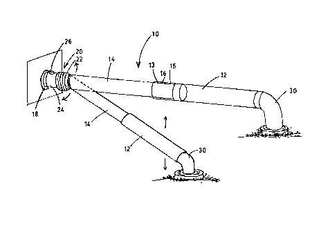
Figure 1 shows an unextended telescopic pipe according
to the invention;
Figure 2 shows the pipe of Figure 1 in extended
condition being used at different angles with respect to a
reservoir;

CA 02232745 1998-03-19
- 3 -
Figure 3 shows the pipe being used from a down spout
eavestrough; and
Figures 4A, 4B, 4C, 4D and 4E are engineering drawings
showing one suitable embodiment of pipe with dimensions.
The pipe 10 of Figures 1 and 2 comprises two telescopic
sections 12, 14 of rigid pipe fabricated from plastics
material. While two sections are shown, three sections may
be more suitable for some purposes, allowing greater
extension with possibly smaller unextended length. Section
12 is of slightly larger diameter than section 14 and waxed
felt seal 16 provided between them may prevent or mitigate
and liquid seepage. Seals 16 may alternatively be rubber or
other conventional material. The extended pipe of Figure 1
may be retracted telescopically into a compact form for
storage by sliding section 14 over section 12 as far as
possible.
An interior stop 13 may be provided at a proximal end
of section 12 to latch with an exterior stop 15 at the
distal end of section 15 to prevent the sections becoming
disengaged. Seal 16 is located on either or both sections
between stops 13 and 15.
In operation, connector 18 is connected to the outlet
of an effluent tank connector 18 may be of any convenient
form to fit standard outlets. The telescopic pipe 10 is
then extended by sliding section 12 outwardly from section
14 to extend the length of pipe 10 until it is sufficient
length to reach the desired delivery point. Sections 12 and
14 as illustrated in the drawings may conveniently be about
four feet in length since this will provide an extended
length of around eight feet which is frequently sufficient
or more than sufficient to reach from a recreation vehicle
effluence tank to a septic system. If greater distances are
required, the pipe 10 may be made of sections of greater

CA 02232745 1998-03-19
- 4 -
length or additional telescopic sections may be provided.
For example, three section may easily provide an extended
length of 11 feet .
An intermediate flexible link 20 may be attached
between connector 18 and section 12. The connecting link 20
may be a short length of corrugated rubber ducting having a
length for example of about 12.5 cm. Only a short section
22 of this link need be corrugated to provide flexibility to
angle the pipe 10 where desired. In a smooth surfaced
portion 24 of the link a flush out nozzle 26 may be provided
connectable through a length of ordinary garden hose to any
suitable tap.
At the distal outlet end of the pipe 10 a reducing link
28 may be used as an exit nozzle or as a connecting link for
a curved nozzle 30 (see Figures 1 and 2) which may be
directed downwardly into a delivery receptacle.
Figure 2 shows the pipe at different extensions and at
different angles, both vertical and horizontal showing the
ease at which the pipe 10 may be adjusted in different
directions over different distances.
Figure 3 shows a different application for pipe 10 in
distributing waste water from eavestrough at different
angles over different distances.
When not in use the unextended pipe 10 may be stowed in
suitable brackets under a recreational vehicle or in a
customized compartment.
Figures 4A, 4B, 4C, 4D and 4E are drawings indicating
specific dimensions of one three section embodiment. Figure
4B shows an intermediate section having stops 13A and 15A
and a seal 16.

Representative Drawing
A single figure which represents the drawing illustrating the invention.
Administrative Status

2024-08-01:As part of the Next Generation Patents (NGP) transition, the Canadian Patents Database (CPD) now contains a more detailed Event History, which replicates the Event Log of our new back-office solution.

Please note that "Inactive:" events refers to events no longer in use in our new back-office solution.

For a clearer understanding of the status of the application/patent presented on this page, the site Disclaimer , as well as the definitions for Patent , Event History , Maintenance Fee  and Payment History  should be consulted.

Event History

Description Date
Inactive: IPC from MCD 2006-03-12
Application Not Reinstated by Deadline 2001-01-19
Inactive: Dead - Application incomplete 2001-01-19
Deemed Abandoned - Failure to Respond to Maintenance Fee Notice 2000-03-20
Deemed Abandoned - Failure to Respond to Notice Requiring a Translation 2000-01-19
Inactive: Correspondence - Formalities 1999-10-27
Inactive: Incomplete 1999-10-19
Inactive: Cover page published 1999-09-23
Application Published (Open to Public Inspection) 1999-09-19
Classification Modified 1998-07-27
Inactive: IPC assigned 1998-07-27
Inactive: First IPC assigned 1998-07-27
Inactive: Filing certificate - No RFE (English) 1998-06-03
Inactive: Applicant deleted 1998-06-02
Application Received - Regular National 1998-06-02

Abandonment History

Abandonment Date Reason Reinstatement Date
2000-03-20
2000-01-19

Fee History

Fee Type Anniversary Year Due Date Paid Date
Application fee - small 1998-03-19
Owners on Record

Note: Records showing the ownership history in alphabetical order.

Current Owners on Record
LLEWELLYN BERTRAM PARSONS
Past Owners on Record
None
Past Owners that do not appear in the "Owners on Record" listing will appear in other documentation within the application.
Documents

To view selected files, please enter reCAPTCHA code :


To view images, click a link in the Document Description column. To download the documents, select one or more checkboxes in the first column and then click the "Download Selected in PDF format (Zip Archive)" or the "Download Selected as Single PDF" button.

List of published and non-published patent-specific documents on the CPD .

If you have any difficulty accessing content, you can call the Client Service Centre at 1-866-997-1936 or send them an e-mail at CIPO Client Service Centre.


Document
Description 
Date
(yyyy-mm-dd) 
Number of pages   Size of Image (KB) 
Claims 1999-09-18 1 2
Abstract 1999-09-18 1 2
Representative drawing 1999-09-22 1 8
Drawings 1998-03-18 7 80
Description 1998-03-18 4 169
Filing Certificate (English) 1998-06-02 1 162
Reminder of maintenance fee due 1999-11-21 1 111
Courtesy - Abandonment Letter (incomplete) 2000-02-08 1 172
Courtesy - Abandonment Letter (Maintenance Fee) 2000-04-16 1 183
Correspondence 1999-10-14 1 11
Correspondence 1999-10-26 1 28
Correspondence 1998-06-08 1 20