Note: Descriptions are shown in the official language in which they were submitted.
CA 02232748 1998-03-19
INJECTION TOOL
Field of the Invention
This invention is directed to a downhole tool and method for use thereof and,
in
particular, a tool and method for downhole injection.
Background of the Invention
In the production of oil and/or gas, sometimes a heavier fluid is produced
with the
desired hydrocarbon fluid. This heavier fluid must be separated from the oil
and/or gas
and disposed of.
Preferably, the undesired heavier fluids are separated from the desired
hydrocarbon
fluids downhole and are injected into a disposal formation without being
brought to
ground surface.
An injection tool is disclosed in U.S. Patent 5,176,216 of Slater et al. The
tool which is
disclosed handles the heavier fluids after they have been separated by
residence time
downhole from the lighter hydrocarbon fluids. The tool allows the heavier
fluids to move
further down the well into a disposal formation. The tool includes a portion
for accepting
and sealing with a pump and has inlet ports through which the heavier liquids
flow into
the tool and thereby into a pump secured to the tool. A plurality of injection
ports are
provided through which liquid from the pump is injected into the disposal
formation.
The tool of Slater is of limited use, however, as the ports to the disposal
formation are
of very small diameter and, therefore, are easily plugged, are susceptibel to
erosion and
CA 02232748 1998-03-19
-2-
also cause a pressure differential through the tool. In addition, the tool is
formed to only
accept non-standard sizes of mandrels and cups.
Summary of the Invention
A downhole tool has been invented which can be used for handling waste fluids
which
have been separated from desired hydrocarbon production fluids. The waste
fluids are
injected into a disposal formation. The tool is produced to avoid blockage of
fluid flow
passages and to reduce or eliminate the creation of a pressure differential
across the
tool. The tool is adaptable to be used with various sizes of pumps, to
accommodate
various pump intake filters and to conform to API tolerances.
In accordance with a broad aspect of the present invention, there is provided
a
downhole tool comprising: an inner tube having a longitudinal bore, a seal
disposed at
the lower end of the longitudinal bore, an outer tube having an outer surface
and being
attached about and spaced from the inner tube; an annulus formed between the
inner
tube and the outer tube and being open at each end; means at the upper end of
the
outer tube to connect the outer tube to a tubing string such that the annulus
opens into
the tubing string's longitudinal bore and a transverse port extending to
provide access
between the longitudinal bore of the inner tube and the outer surface of the
outer tube
without opening into the annulus.
The seal in the longitudinal bore can be any suitable means for sealing the
bore such
as an end wall formed integral with the inner tube or a plug secured in the
bore of the
inner tube.
A coating of non-stick and/or erosion resistant material can be applied to at
least some
of the surfaces of the tool and, preferably, at least those surfaces defining
the
transverse port, the longitudinal bore of the inner tube and the annulus. A
particularly
preferred coating material is a polymer such as a fluoropolymer, for example,
one
CA 02232748 1998-03-19
-3-
known as ImpreglonTM
Thus, in accordance with another broad aspect of the present invention, there
is
provided a downhole tool comprising: a tubular member having at least one
unobstructed longitudinal conduit extending in the wall thereof from one end
of the
tubular member to the other and at least one transverse port extending through
the wall
of the tubular member without intercepting any longitudinal conduit; means to
connect
the tubular member to a tubing section wherein the at least one longitudinal
conduit
opens at one end into the tubing section's inner bore and a seal at one end of
the
tubular member, the improvement comprising: a coating of non-stick and/or
erosion
resistant material applied to at least some of the surfaces of the tool.
Preferably, the coating material is applied to all of the surfaces of the tool
or at least
those surfaces defining the transverse port, the longitudinal bore of the
inner tube and
the annulus. A particularly preferred coating material is a polymer such as a
fluoropolymer, for example, ImpreglonTM
For use in injection, a pump is attached to the tool so that the pump is in
communication
with the bore of the inner tube. In one embodiment, the tool can be used with
a pump
having an intake filter attached thereto. In this embodiment, the inner tube
is preferably
selected to have a length suitable for accommodating the pump filter therein.
Generally, the inner tube has a length of about 6 to 12 inches from the end
seal to the
upper edge of the tube.
In another embodiment, the inner tube of the tool has means for engagement to
a pump
such as, for example, a threaded portion or a J-Iock arrangement for
engagement to a
corresponding threaded portion or J-Iock portion on the pump.
It may be desirable to use the same tool for many applications. Thus, it is
desirable that
the tool be able to be modified for use in many applications and, for example,
with
CA 02232748 1998-03-19
-4-
various sizes of pumps or pump hold down apparatus, with various pump
attachment
means and with or without pump intake filters. Most of the variations for use
in different
applications requires changes to be made to the inner tube. Thus, in one
embodiment,
at least a portion of the inner tube is removable and, thereby, replaceable.
In particular,
preferably the inner tube is formed of an upper inner tube and a lower inner
tube, the
upper inner tube and the lower inner tube being connectable to form a fluid
tight seal
therebetween and the upper inner tube being removable from the remainder of
the tool.
There can be many forms of the upper inner tube to suit the use to which the
tool is to
be put. As an example, the upper inner tube can be formed for accepting a pump
and
can have a formed thereon a means for connection to a pump such as a threaded
portion or a J-Iock arrangement.
In another embodiment, the outer tube is also formed as two parts: an upper
outer tube
and a lower outer tube. Preferably, the upper outer tube is releasably
connected to the
lower outer tube being connectable to form a fluid tight seal therebetween and
the
upper outer tube being removable from the remainder of the tool.
To facilitate use of the tool with some pump types, in one embodiment the tool
includes
a valve mounted on the tool to regulate the flow of fluid out of the annulus.
In another embodiment, the minimum cross sectional area of the annulus is
selected
to correspond to the discharge area of the pump which is used with the tool.
In accordance with another broad aspect of the present invention, there is
provided a
downholp, tool comprising: a tubular member having at least one unobstructed
longitudinal conduit extending in the wall thereof from one end of the tubular
member
to the other and at least one transverse port extending through the wall of
the tubular
member without intercepting any longitudinal conduit; means to connect the
tubular
member to a tubing section wherein the at least one longitudinal conduit opens
at one
end into the tubing section's inner bore and a seal at one end of the tubular
member,
CA 02232748 1998-03-19
-5-
the improvement comprising: the tool including a valve positioned to regulate
the flow
of fluid through the at least one longitudinal conduit.
Preferably, the valve is mounted on the tool and adjacent the outlet of the
longitudinal
conduit. The valve can be positioned at any location on the tool provided it
is capable
of regulating flow through the bottom end of the longitudinal conduit.
Preferably, the
valve is mounted on the tool at the bottom end thereof.
In accordance with another broad aspect of the present invention, there is
provided a
downhole injection assembly for passing waste fluids through a well borehole
from a
production layer to a disposal layer, the well borehole having a wall
extending from
surface, the assembly comprising; a tool including an inner tube having a
longitudinal
bore, a seal disposed at the lower end of the longitudinal bore, an outer tube
having an
outer surface and being mounted about and spaced from the inner tube; an
annulus
formed between the inner tube and the outer tube and being open at each end;
means
at the upper end of the outer tube to connect the outer tube to a tubing
string such that
the annulus opens into the tubing string's longitudinal bore and a transverse
port
extending to provide access between the longitudinal bore of the inner tube
and the
outer surface of the outer tube without opening into the annulus; a tubing
string
connected to the upper end of the outer tube; and a pump, having a known
discharge
area, in pumping communication with the longitudinal bore of the inner tube.
In accordance with yet another broad aspect of the present invention there is
provided
a method for passing waste fluids through a well borehole from a production
layer to a
disposal layer, the well borehole having a wall extending from surface,
comprising;providing a downhole tool including an inner tube having a
longitudinal bore,
a seal disposed at the lower end of the longitudinal bore, an outer tube
having an outer
surface and being mounted about and spaced from the inner tube; an annulus
formed
between the inner tube and the outer tube and being open at each end; means at
the
upper end of the outer tube to connect the outer tube to a tubing string such
that the
CA 02232748 1998-03-19
-6-
annulus opens into the tubing string's longitudinal bore and a transverse port
extending
to provide access between the longitudinal bore of the inner tube and the
outer surface
of the outer tube without opening into the annulus; connecting the outer tube
to a tubing
string; placing a pump in pumping communication with the longitudinal bore of
the inner
tube; positioning the tool, tubing section and the pump in the borehole such
that the tool
is in pumping communication with waste fluids passing from the production
zone;
setting a sealing means about the tool between the transverse port and the
lower
opening to the annuius; activating the pump to move waste fluids in through
the
transverse port and through the inner tube bore.
The well borehole wall can be the wall in an uncompleted well or the casing
forming the
wall of a cased well. The sealing means can be attached to the tool or can be
mounted
on an extension tube attached to and extending below the outer tube.
Brief Description of the Drawings
A further, detailed, description of the invention, briefly described above,
will follow by
reference to the following drawings of specific embodiments of the invention.
These
drawings depict only typical embodiments of the invention and are therefore
not to be
considered limiting of its scope. In the drawings:
Figure 1 shows a schematic representation of a vertical section along a cased
borehole, the borehole having an injection tool disposed therein;
Figure 2 shows a longitudinal section through an injection tool according to
the
present invention;
Figure 3 is a cross sectional view along line 3-3 of Figure 2; and
Figure 4 shows a longitudinal section through another injection tool according
to
CA 02232748 1998-03-19
-7-
the present invention.
Detailed Description of the Present Invention
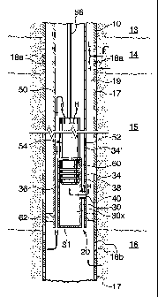
Referring to Figure 1, a sectional schematic view along a well is shown. The
well
borehole, indicated at 10, passes from surface (not shown) through a formation
including an upper layer (not shown), an impermeable rock layer 13 below the
upper
layer, a production layer 14, a second impermeable layer 15 and a disposal
layer 16 of
permeable rock. Borehole 10 is lined with a casing 17 and is completed to
prevent
interzonal migration in the casing annulus. Upper perforations 18a are formed
in
casing 17 to provide access from the casing tube to the production layer 14
and lower
perforations 18b are formed in casing 17 to provide access to disposal layer
16. The
production layer 14 produces both a desired lighter hydrocarbon fluid, such as
oil and/or
gas, and a heavier waste fluid, such as water. Both of the fluids pass from
the
production layer through perforations 18a into casing 17. After a suitable
residence
time in the casing, for example one minute, the lighter fluids, such as gas,
will be
separated from the heavier fluids by density and gravity. Lighter fluids, such
as gas,
will pass, due to density and pressure, up the borehole opening 19, as
indicated by
arrows L. Fluids such as oil may require active separation from the waste
fluids and
may further require active pumping up the borehole after they are separated
from the
heavier fluids. The heavier fluids will pass by gravity further down the
borehole, as
indicated by arrows H.
The injection tool according to the present invention is shown schematically
in Figure
1 and is generally indicated as 20.
Tool 20 includes an inner tube 30 having a longitudinal bore 30x. A wall 31 is
formed
at the lower end of bore 30x to seal off the bore at the lower end. Wall 31
can be
formed integral with inner tube 30 or can be a plug or other sealing means. An
outer
tube 34 is mounted substantially concentrically about inner tube 30. Outer
tube 34 is
CA 02232748 1998-03-19
-8-
mounted in spaced relation from inner tube 30 such that an annulus 36 is
formed
therebetween. Inner tube 30 and outer tube 34 are mounted together and annulus
36
is formed by any desired process such as by milling along the length of a wall
of a tube
to form an inner tube and an outer tube which are connected and have an
annulus
therebetween. Alternately, and as shown in the depicted embodiment, spacers 38
are
secured between inner tube 30, and outer tube 34, for example by welding or
fasteners,
to maintain the spacing between the tubes. Spacers 38 are disposed between the
tubes such that annulus 36 is not at any point completely blocked off and an
open
longitudinal conduit is between the tubes through the annulus between the
lower and
upper ends of tubes 30, 34.
The tool also includes at least one transverse port 40 which extends between
and
connects the inner bore 30x of inner tube 30 to the outside of the tool
without opening
into the annulus 36. Each port 40 is formed in any suitable way, for example
by placing
a tube in sealing arrangement between an opening formed in inner tube 30 and
an
opening formed in outer tube 34. Where a spacer 38 is used to form annulus 36,
port
40 can be formed conveniently by drilling an opening through the spacer, as
shown.
In so doing, it is necessary that a seal be provided at the interface between
the spacer
and the tubes where the port passes to prevent passage of fluid from the port
through
the interface.
For use in the injection of waste fluids, tool 20 is preferably connected at
its upper end
into an upper tubing string 50. Tubing string 50 is connected in any suitable
way to
upper end 34' of outer tube 34, for example by threaded connections 52 or
other means
such as collars, welding or swedges.
A pump 54 is inserted within tubing string 50 and is attached to communicate
with the
inner bore 30x of inner tube 30. Pump 54 can be any suitable pump for downhole
operation such as, for example, a rod pump, as shown, a progressing cavity
pump or
an electric submersible pump. When pump 54 is a rod pump, a pumping rod 56
CA 02232748 1998-03-19
-9-
extends from the surface between a reciprocating means (not shown), such as a
pump
jack, and the pump. As is known, reciprocating movement of the reciprocating
means
is translated to pump 54 through rod 56 to cause pump 54 to pump liquid. The
pump
is maintained in communication with the bore 30x of inner tube 30 by any
suitable
means such as, for example, hold down apparatus 60 which is engaged to the
pump,
such as by threaded attachment. Hold down apparatus is inserted into the
longitudinal
bore of inner tube 30 and is frictionally engaged therein. Alternately, pump
can be
engaged, directly or through a cross over or swedge, to the inner tube. This
requires
that a physical connection system be provided on the inner tube such as, for
example
a threaded connection or J-Iock assembly which corresponds to that on the
pump.
A sealing means 62, such as a packer, is provided about or below the tool to
effect a
seal between tube 34 and casing 17. The seal is required to be positioned
between
transverse port 40 and the lower opening of the annulus. The lower opening of
the
annulus can be, in effect, lowered by attaching a tube to the outer tube to
extend it
downwardly. Thus, the sealing means can be mounted about the outer tube or can
be
mounted on an extension tube attached to the outer tube, as by threaded
connection,
and extending below the tool. Sealing means 62 can be a packer or any other
sealing
means which can be placed around a tube to block passage of fluid about the
tool and
through the well bore. Preferably, the sealing means are retractible so that
the well
bore seal can be removed to permit removal of the tool from the well. For
example, the
sealing means can be an inflatable/deflatable packer or a mechanical packer.
As noted hereinbefore, tool 20 is useful for injecting heavier fluids to a
disposal layer
16 below the tool. The tool is positioned below perforations 18a and the
sealing means
is set to seal between the tool and the casing. The heavier fluids move by
gravity,
arrow H, toward the tool. Sealing means 62 creates a seal between casing 17
and tool
20 so that heavier fluids accumulate around the tool and enter the tool
through ports 40.
Pump 54 is driven to pump the fluids in through ports 40, up through bore 30x
of the
CA 02232748 1998-03-19
-10-
inner tube and up through pump 54. The liquids will spill out of pump 54 into
the bore
of tubing string 50 and will move by gravity down toward tool 20. When the
liquid
reaches the tool, it will pass through annulus 36 and out the lower end
thereof into the
casing 17 adjacent the disposal layer 16. The liquid will then flow through
perforations
18b into the disposal layer.
Referring to Figures 2 and 3, a preferred embodiment of the tool is shown.
Outer tube
34 is mounted about and spaced from inner tube 30. End 34' of tube 34 is
formed for
threaded connection into a tubing string, such as that shown as tubing string
50 in
Figure 1, and lower end 34" of tube 34 is formed for threaded connection to a
lower
extension tube (not shown) which attaches to a packer. Packers are known in
the art.
Spacers 38 are positioned between the tubes. Preferably, spacers 38 are formed
integral with inner tube 30 and outer tube 34 is attached, as by welding or
any other
suitable means, to at least some of spacers 38. Where welding is used, as
indicated
at 39b, slots 39x can be provided or formed in outer tube 34 to facilitate
such welding.
After welding the parts together, preferably, three ports 40 are formed, as by
drilling,
through the spacers to provide access between bore 30x of inner tube 30 and
the outer
surface 34x of outer tube 34. Weld 39b is preferably made such that it effects
a seal
at the interface between spacers 38 and outer tube 34 about ports 40. Where
the weld
or other means of attachment of the outer tube to the spacers does not provide
a seal
at the interface of the parts around the ports 40, other sealing means must be
provided
about the ports.
Annulus 36 is formed between the tubes 30, 34. Access to annulus 36 is
provided at
upper opening 66 and lower opening 68. In one embodiment, the minimum cross
sectional area of the annulus is selected to correspond to the total cross
sectional area
of ports 40. (In the tool, as shown, the position where the annulus cross
sectional area
is at a minimum is shown in Figure 3. This is the area where the transverse
port walls
extend through the annulus.) In particular, the total cross sectional area of
ports 40 is
CA 02232748 1998-03-19
-11-
selected to be between about 85% to 105% and, preferably, between about 95% to
105% of the minimum cross sectional area of the annulus. In a preferred
embodiment,
the total combined cross sectional area of the transverse ports is selected to
be about
equal to the minimum cross sectional area of the annulus. In a tool according
to the
present invention having a 3.5" diameter and suitable for use in a casing
having a
diameter of 4.5" or greater, the total combined cross sectional area of the
ports is
selected to be about 1.6 square inches (i.e. each of the ports has a cross
sectional area
of 0.53 square inches) and the minimum cross sectional area of the annulus is
also
about 1.6 square inches.
To facilitate flow of liquid into the annulus, preferably upper end 30' of
inner tube is
chamfered, as shown.
Erosion and the build up of scale in the liquid conduits of the tool has
limited the useful
life of prior art injection tools. To accommodate any wear due to erosion
which will be
experienced over the life of the tool, the minimum wall thicknesses of the
outer tube,
inner tube and transverse ports are selected to be greater than 0.18 inches
and
preferably are selected to be between about 0.23 and 0.27 inches. To reduce
the
effects of erosion and to reduce the accumulation of scale in the liquid
conduits,
preferably the interior of the transverse ports, the walls of the inner and
outer tubes
which define the annulus and the inner bore of the inner tube and preferably
all
surfaces of tool is coated with a material which is resistant to erosion
and/or to the
attachment of scale. A suitable material is, for example, a fluoropolymer such
as, for
example, ImpreglonTM. The coating material can be applied in any suitable way
such
as, for example, by spraying, dipping or painting.
An injection tool which is adaptable to accept various pump hold down
apparatus or
pump connections or other assemblies such as intake filters is desirable and
is not
previously known. The tool of Figure 2 is useful in this way. The upper
portion of the
tool is formed to be detachable from the remainder of the tool and is,
thereby,
CA 02232748 1998-03-19
-12-
replaceable. In particular, inner tube 30 is formed as an upper inner tube 30a
and a
lower inner tube 30b. Upper inner tube 30a and lower inner tube 30b are
releasably
connected at a connection 64a, preferably by threading, which is disposed
above ports
40. Outer tube 34 is formed as an upper outer tube 34a and a lower outer tube
34b
which are releasably connected at connection 64b, preferably by threading.
Connection
64b is also positioned above ports 40. Lower outer tube 34b is mounted about
lower
inner tube 30b and an annulus 36b is formed therebetween. Tubes 30a and 34a
align
with tubes 30b and 34b, respectively, and are sealably connectable at
connections 64a,
64b, respectively. When the upper tubes 30a and 34a are connected at
connections
64a, 64b to the lower assembly, an annulus 36a is formed therebetween and
annulus
36a opens into annulus 36b. Preferably, upper inner tube 30a and upper outer
tube are
not connected at interface 39a, such that upper inner tube 30a and upper outer
tube
34a can each be removed independently from the assembly of the lower outer
tuve and
the lower inner tuve. Spacers 38 are preferably attached on upper inner tube
30a to
provide for centralization and stability of the upper inner tube within the
upper outer
tube.
A tool which has a removable upper portion, as shown, permits that various
upper
sections can be produced having as an example a) inner tubes with various
inner
diameters selected to accept hold down apparatus having selected different
outer
diameters, b) inner tubes of selected lengths (i.e. 6 to 12 inches) to
accommodate
various types of pump filters, c) inner tubes with threaded connections at
their upper
end for connection to a pump or d) combinations of any of the foregoing. These
upper
sections, which cost less to manufacture that the ported lower section, can be
attached
to and detached from the lower section and replaced, as desired for the
selected
application for which the tool is to be used. Alternately, the upper portion
of the inner
tube can be removed altogether and a pump can be threaded directly to lower
inner
tube 30b. Thus, the usefulness of the tool is increased over one-part tools.
The tool of Figures 2 and 3 can have attached thereto an upper tubing string,
a pump
CA 02232748 1998-03-19
-13-
assembly and a sealing means and can be used in the same manner as was
described
with reference to Figure 1.
In an embodiment, the minimum cross sectional area of the annulus is selected
to
correspond to the discharge area of the pump which is intended to be attached
to the
tool. In particular, the minimum cross sectional area of the annulus is
selected to be at
least 90% of the discharge area of the pump. As an example, for use with a
pump
having a 1.23 square inch to 1.77 square inch discharge area (for example a
standard
1.25 to 1.5 inch pump), a preferred tool has an annulus with a minimum cross
sectional
area of 1.6 to 1.77 square inches. Preferably, the tool is selected such that
the
minimum cross sectional area of the annulus is substantially equal to or
greater than
the discharge area of the pump with which it is to be used. A tool which is
selected with
consideration to the pump to correspond with the pump discharge reduces the
load on
the pump and on any seals in the system and addresses pressure and velocity
concerns inherent with the use of prior art injection tools.
Referring to Figure 4, another tool according to the present invention is
shown. In the
illustrated embodiment, a valve 80 is provided at the lower opening 68 of
annulus 36.
Valve 80 is normally closed but can be opened by application of a selected
degree of
force, such as the weight of a column of water, applied to the valve from
within annulus
36. In particular, valve 80 can include, for example, a sealing flange 82
positioned to
cover and seal against opening 68 of annulus 36, a biasing means 84 such as a
coil
spring for biasing flange 82 against the opening and a screw 86 and a washer
87, or
other valve mounting means, for securing the valve assembly in position at the
bottom
of the tool. The valve can be according to that illustrated or any other
pressure
actuated valve, for example, a flapper valve or a ball and seat type valve.
The tool of Figure 4 is particularly useful with an electrically driven pump.
The valve is
selected to create a build up of water in the pump so that a water load is
placed on the
pump. As is known, the electrical consumption of the pump can be monitored to
CA 02232748 1998-03-19
-14-
determine if there exists a water load on the pump. When no water load is
detected,
it can be determined that the pump is operating dry and can be shut down.
It will be apparent that many other changes may be made to the illustrative
embodiments, while falling within the scope of the invention and it is
intended that all
such changes be covered by the claims appended hereto.