Note: Descriptions are shown in the official language in which they were submitted.
CA 02232993 1998-03-25
1
Coupling
TECHNICAL AREA
The present invention relates generally to hose couplings
and, more particularly, to couplings for disconnectible
connection of a thick hose pipe to a container, the coup-
ling being of the type comprising a male member intended
to be permanently mounted at the container, and a female
member intended to be permanently attached to the hose
and which in its connected position can by a rotational
movement be locked together with the male portion.
BACKGROUND
Couplings of this type are above all used for filling
tank lorries and the like from the bottom, the male
portion as well as the female portion then having self-
closing valve which are opened upon interlocking of the
two coupling members, generally by means of a locking
device of the bayonet catch type. In previously known
couplings during a locking phase rolls are caused due to
the relative rotation to run in inclined cam grooves
arranged in the inner surface of the female member. The
rolls are mounted on a transversal shaft in the female
member housing, said shaft being connected to the valve
piston in the female member. In this way that valve
piston is urged into the male member whereby there is
formed a through opening so that liquid or gas can freely
flow through the coupling.
Especially in the above-mentioned use where the male
member is located at the bottom of the tank, the inter-
connection of the two coupling members must often take
place in narrow spaces calling for a sharp bending of the
thick hose which in most cases has a diameter of 6-8 cms
and thick walls in order to withstand the rather high
CA 02232993 1998-03-25
2
pressures - often of the size of magnitude 0.7-1.0 Pa.
This results in the coupling often being exposed to very
powerful breaking stresses acting upon the connection
between the male and the female members.
In known hose couplings these stresses cause problems
involving inter alia material friction, especially
between the rolls and the shaft on which said rolls are
mounted, and between the rolls and the cam grooves. This
problem is amplified by the fact that, in prior art
embodiments, it was necessary to use a short actuator
acting upon the piston resulting in an unsatisfactory
stability in the coupling. For that reason certain coup-
lings comprise a spring package making the structure
stiffer.
A further example of the standing of the art is described
in US 3,441,055 (Pickell).
THE OBJECT OF THE INVENTION
The object of the present invention is to avoid the
above-mentioned disadvantages in previously known hose
couplings.
SUMMARY
The above-mentioned object is attained by use of the
realization that, if the actuator is shaped so as to act
directly upon the transverse shaft, the above-mentioned
disadvantages are avoided and the result will be a hose
coupling in which the friction has been reduced and the
rigidity increased in comparison with prior art coup-
lings.
Accordingly, a hose coupling member comprising a housing
with a through opening and grooves obliquely directed
along the inner surface of the housing, a piston for
sealing said through opening, a transverse shaft connec-
CA 02232993 1998-03-25
3
ted to said piston, and an actuator located inside said
housing, said shaft engaging said grooves and generating
a linear relative movement between the housing and the
piston in response to a relative rotation between the
housing and the actuator, is characterized in that the
actuator comprises openings located in the acutator and
receiving the transverse shaft, whereby, in response to a
relative rotation between the housing and the actuator,
the part of the actuator defining the openings acts
directly on the transverse shaft in a direction parallel
to the direction of rotation, whereby the piston connect-
ed to the shaft is rotated relative to the housing.
This arrangement permits use of a longer actuator which
improves absorption of breaking stresses. This also makes
it possible to dispense with the spring package which in
prior art hose couplings is installed to absorb breaking
stresses, the result being a reduced friction during the
mutual rotation of the coupling members and a cheaper and
more reliable hose coupling.
Preferably there are arranged two sets of rolls mounted
on the shaft: one set of outer rolls running in the
obliquely directed grooves, and one set of inner rolls
running in openings in the actuator.
Further characteristics of the invention will appear from
the subclaims.
SHORT DESCRIPTION OF THE DRAWINGS
The invention will below be described in greater detail,
reference being made to the attached drawings in which:
Figure 1 does diagrammatically show the location on a
tank of the members of a hose coupling according to the
invention,
CA 02232993 1998-03-25
4
Figure 2 illustrates the members making up the hose
coupling,
Figure 3 is a cross-sectional view through a male coup-
s ling member known per se,
Figure 4 is a cross-sectional view through a female
member in the hose coupling according to the invention,
l0 Figure 5 shows the members illustrated in Figs 3 and 4
brought together but not interconnected,
Figure 6 shows the members illustrated in Figs 3 and 4
brought together and interconnected,
Figure 7 does in greater detail show a cam portion form-
ing part of the male member, and
Figure 8 shows an alternate embodiment of an actuator in
the hose coupling.
EMBODIMENTS
Structural features
In Fig. 1 70 designates the lower part of a container
which, by way of example, may be a tank mounted on a
vehicle, the male member 4 of a hose connection coupling
being permanently mounted in the bottom of the tank.
This male member, which is shaped like a tubular nipple
comprising a self-closing valve, forms a tube-like elong-
ation of a opening in the bottom of the tank 70 and is
arranged to cooperate with a female member 2 attached to
the end of a thick hose 72. The female member 2 is in-
tended to surround the bottom end of the male member 4
and to be secured thereto by means of a bayonet locking
device and upon rotation of the female member 2. The
female member also comprises a self-closing valve which,
CA 02232993 1998-03-25
like the valve in the male member 4, is opened when the
two coupling members are joined together.
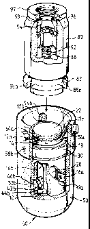
Figure 2 is a perspective view showing a preferred hose
5 coupling according to the invention comprising the male
member 4 known per se and the novel female member 2
embodying the invention.
The male member known per se, which is in a sectional
view shown also in Figure 3, comprises a cylindric hous-
ing 82 mounted on the tank 70 (see Figure 1) by means of
a mounting device 97 having a bushing 94 and a flat-
packing 96 as well as a O-ring 98 for sealing up the
housing. In the housing 82 of the male member the end
opposite to the mounting device 97 is provided with a
piston 84 which is mounted longitudinally movable in the
housing and held spring-biased in its outer position by
means of a helical spring 88 resting against a support 92
in the housing. An O-ring 86 provides sealing between the
housing and the piston 84 in its outer position.
The female member 2, also seen in cross-section in Figure
4, does also comprise a housing 50 arranged to engage the
male member housing 82. For that reason housing 50 comp-
rises a peripheral flange 51 the inner diameter of which
is slightly greater than the outer diameter of the male
member housing 82 so that the female member can be
brought to enclose the one end of the male member when
the two members shall be brought together. When members
2, 4 have been brought together, they are rotated rela-
tively each other, whereby locking rolls 54a-c mounted on
shafts 56a-c engage behind projections 83 mounted on the
male member housing 82.
In the housing 50 there is disposed a cylindric cam means
30 exhibiting two obliquely directed cam grooves 32a, b.
The shape of those grooves appears more clearly from
CA 02232993 1998-03-25
6
Figure 7. Between housing 50 and cam means 30 there is
mounted an O-ring 52 providing sealing between those two
parts. The cam means is secured to housing 50 by two
locking screws 58a, b passing through the housing and the
cam means. If required, more than two locking screws may
be used.
Inside the cam means 30 there is in turn loosely mounted
a cylindric actuator 10, made e.g. of brass, steel or
aluminium or of any other material suitable for the
purpose. At its one end the actuator has three protru-
sions 12a-c arranged to engage corresponding recesses
85a-c in the male member housing 82. The protrusions
carry fence flanges 19a-c preventing the lock rolls 54a-c
from sliding off its related shaft. Further, there is an
O-ring 14 in a peripheral groove, said O-ring providing
sealing between the male member housing 82 and the actua-
tor 10 when the two coupling members 2, 4 have been
brought together. There is also a slide washer 18, for
instance of teflon, disposed between the outer portion of
the actuator 10 and the cam means, as well as a wear or
guide ring 36 e.g. of teflon. The function of the two
last-mentioned components is to reduce the friction when
the actuator 10 and the cam means 30 are caused to rotate
relatively each other.
As has been mentioned before and as appears from the
drawings, actuator 10 is substantially cylindric but in
the envelope surface there are two openings, or recesses,
16a, b. Those openings are elongated in the directiion of
the longitudinal axis and have smoothly rounded ends for
manufacturing and strength reasons. The openings receive
a transversal shaft 40 which will below be described in
greater detail.
The actuator can be almost equally long as the housing 50
in which it is mounted. This means that the breaking
CA 02232993 1998-03-25
7
forces between the coupling halves referred to in the
introductions can be absorbed in a better way than if the
length were substantially smaller. Also, this does also
reduce the wear which upon rotation takes place between
the rolls 42a, b in the cam grooves and the housing 50
and between the cam means 30 and the actuator 10. In
addition, this makes it possible to omit the spring
package used in many prior art hose couplings for the
purpose of making the actuator more rigid. However, in
order to simplify the manufacturing process and to reduce
the consumption of material and thereby also the weight
the actuator can be made somewhat shorter than what
appears from Figs 2 and 4. In Figure 8 there is shown a
modified actuator at which the outermost end turned away
from the surface engaging the other coupling half has
been cut. This does only very little lower the capacity
to absorb breaking stresses.
Inside the actuator 10 there is a piston 20 displaceable
in the direction of the longitudinal axis. The piston has
a contact surface 22 of a slightly smaller dimension than
the piston 84 in the male member. Further, adjacent to
said contact surface the piston has a peripheral groove
in which there is disposed an O-ring 23 for sealing
between actuator 10 and piston 20.
In a transversal bore 24 in the piston, adjacent to its
end opposite to the contact surface, there is a shaft 40,
the shape of which does most clearly appear from Figure
4. The mounting position of the shaft is maintained by
means of a locking pin 28 engaging a recess 26 in the
piston substantially along the longitudinal axis of the
piston.
Mounted on shaft 40 are two roll pairs, a pair of first,
outer rolls 42a, b and a pair of second, inner rolls 44a,
b. The inner rolls run in the recesses 16a, 16b in the
CA 02232993 1998-03-25
8
actuator whereas the outer rolls run in the cam grooves
32a, 32b in the cam means. Farthest out on shaft 40, at
the end surfaces thereof, there are mounted caps 46a, 46b
of a low-friction material, e.g. teflon, in order to
reduce the friction between shaft 40 and the inner side
of housing 50.
At the end of the female member housing 50 there is in a
known manner attached a hose 72 (shown in Figure 1) or
the like by means of a hose receiver 60 comprising e.g. a
screwed or integrated swivel (not shown) and a flat
package 62 of teflon or vulculan.
Mode of operation
The function of the hose coupling according to the inven-
tion will now be described, Figure 5 showing a cross-
section through the female and male members 2 and 4,
respectively, brought together but not interconnected and
locked to each other, whereas in Figure 6 the coupling
halves have been shown in a mutually locked position
following an approximately 100° rotation, the passage
between the coupling halves being open.
In the initial position, shown in Figure 5, the coupling
halves have been brought together into a position in
which the protrusions 12 on the actuator of the female
member engage the recesses 85 in the male member housing
82. When the housings 50, 82 of the coupling members 2
and 4, respectively, are rotated mutually, the actuator
will accompany the male member housing 82, i.e. the
actuator is caused to rotate in and relatively the female
member housing 50 and cam means 30. The inner rolls 44a,
44b mounted on shaft 40 and running in the openings 16a,
16b in the actuator participate in that rotational move-
ment. In this way also piston 20 is caused to rotate
relatively the female member housing 50 and the cam means
30.
CA 02232993 1998-03-25
9
When shaft 40 and, consequently, also piston 20 is rota-
ted, the outer rolls 42a, 42b are forced to move in the
oblique cam grooves 32a, 32b in the cam portion. They
have such an inclination that to shaft 40, and according-
1y also to piston 20, is without any difficulty imparted
a linear movement relatively housing 50 in the direction
towards the other coupling half 4. This movement does in
turn force piston 84 into the male member housing 82
causing compression of helical spring 88. When the mem-
bers have been rotated by about 100°, the outer rolls
42a, b reach their end positions in the cam grooves 32a,
b, so that continued rotation is blocked. A return move-
ment of the rolls in the cam grooves is then counteracted
by a small projection (not shown), so that a locking
position is attained.
Piston 20 has then been pressed that deep into the other
coupling half 4 that a fluid in gas or liquid state can
freely pass through the coupling along the routes marked
with arrows in Figure 6. Thanks to the cylindric shape of
piston 20 the flow pattern will, as compared with prior
art couplings, become softer resulting in an improved
fluid flow.
When the coupling halves are to be disconnected, the
houses are rotated relatively each other in the direction
opposite the locking direction, so that the outer rolls
42a, b and accordingly also piston 20 will resume their
initial positions as will also piston 84 in the male
member, whereby fluid flow through the coupling is pre-
vented.
In Figure 8 there is shown an alternative embodiment of
actuator 10. Since it is fixed in the axial direction its
end facing the hose can be cut, so that there is created
an actuator which is both lighter and simpler to manu-
f acture .
CA 02232993 1998-03-25
Due to the fact that the female member according to the
invention can function together with existing male mem-
bers having the same coupling socket there is attained an
exchangeability making it unnecessary to replace the male
5 members which, naturally, is an advantage.
While there has above been described preferred embodi-
ments of the invention the skilled artisan will realize
that they can be varied and modified within the scope of
10 the annexed claims. The materials suggested can be
varied, for example in the way that the slide components
are made from other materials than teflon having a low
coefficient of friction. Also, the materials used in the
other components may be varied to match the substances
for which the hose coupling is to be used.
According to the preferred embodiment there are used
rolls 42a, b and 44a, b. Naturally, they can be omitted
or replaced by guide or slide blocks performing the
corresponding function.
Further, shaft 40, which in the preferred embodiment is
disconnectably secured to piston 20, may also be integral
with the piston proper.
Fence flanges 19a-c may advantageously be replaced by
pins inserted in projections 12a-c and yielding the same
function. This simplifies the manufacturing of the actua-
tor.
It is not necessary for the openings, or recesses, 16a, b
in the actuator to have smoothly rounded ends but may be
straight or have some other shape fitting the purpose.
Not withstanding the fact that in the device shown there
are grooves 32a, b in the inner surface of housing 50 in
which shaft 40 runs, the opposite arrangement is also
CA 02232993 1998-03-25
11
imaginable, meaning that on the inner surface of the
housing there are obliquely oriented projections engaging
the shaft.