Note: Descriptions are shown in the official language in which they were submitted.
CA 02233057 1998-03-24
42-28976.1-Disclosure
PRODUCED WATER AND LIGHT HYDROCARBON LIOUID VAPOR IN~BCTION
METHOD AND APPARATUS
FIELD OF INVENTION
The present invention relates to a method and an apparatus for
producing a vapor for injection into a well. The vapor is preferably produced
from
at least one of produced water and light hydrocarbon liquid obtained from a
hydrocarbon production well.
BACKGROUND OF INVENTION
The oil and gas industry presently uses a variety of thermal recovery
methods such as cyclic steam injection, steam drive and steam assisted gravity
drainage (SAGD) to produce hydrocarbons, and in particular crude oil, from
hydrocarbon producing wells. These thermal recovery methods are most
commonly used in oil reservoirs where the oil is of low to medium gravity and
the
viscosity is high. The viscosity of oil decreases rapidly with increases in
temperature. This is particularly dramatic with low gravity crude oils.
Heating the
oil in-situ with high temperature steam injection has been found to be highly
effective in increasing the mobility of the oil. As a result of the steam
injection, the
oil flows more readily by gravity or by one or more other driving mechanisms
to the
production well, where it flows or is pumped to the surface.
Conventionally, these thermal recovery methods utilize steam
injection into the wellbore. More particularly, the steam is typically
produced by a
once through or single pass water tube steam boiler. A feedwater pump
pressures
the feedwater to the required pressure level and forces it through the steam
boiler
piping or tubing that surrounds the gas or oil fired burners. The feedwater is
heated,
vaporized and forced directly down the steam injection well. Typically, the
steam
boiler converts approximately 80% by weight of the feedwater to steam. The
remaining 20% by weight of the feedwater is left as a liquid to carry any
solids in the
feedwater and to inhibit their deposition on the tube walls of the steam
boiler.
Deposited solids or scale tend to insulate the tube walls and reduce any heat
transfer
-1-
CA 02233057 1998-03-24
therethrough. This locally reduced heat transfer allows the flame from the
burners
of the steam boiler to heat the tubing to extreme high temperatures, which may
result in a tube rupture.
Although 20% by weight of the feedwater is left as liquid to carry any
solids, it is still necessary when utilizing conventional steam injection
processes and
equipment to utilize feedwater with a hardness of substantially zero in order
to
substantially prevent or significantly inhibit any scaling. Thus, the hardness
of the
feedwater must often be reduced prior to its use by softening or otherwise
pretreating the feedwater. Ion exchange softeners are commonly used for this
purpose. Ion exchange softeners are typically a train-connected, dual bank
cationic-
exchange resin system, using zeolite as the resin. The beds are alternatingly
regenerated with sodium cloride. In addition, water used in steam generaters
must
typically be free of corrosive gases such as oxygen, Gabon dioxide, and
hydrogen
sulfide. Otherwise, the corrosive gases can cause corrosion to the hot, water
wet,
inner surface of the tubes in the steam generater. Various chemicals including
sodium sulfite are typically used to scavenge the oxygen and thus limit
corrosion.
Large quantities of feedwater are typically required for the operation of
conventional thermal recovery or steam injection processes and equipment.
However, as discussed above, large quantities or sources of good quality
feedwater
are difficult to find. Surface water may be obtained from either lakes or
rivers,
however, this water may contain silt, bacteria, algae, dissolved minerals and
gases.
Water from these sources tends to require filtering in order to remove any
undissolved solids and to prevent fouling of the resin beds of the wafer
softeners.
Fresh ground water produced from wells may not require filtering but tends to
be
higher in total dissolved minerals or solids (TDS). As well, the use of both
surface
water and fresh ground water from wells is restricted by government
environmental agencies. Higher TDS water from deeper wells may be used but
capital and operating costs to treat the water tend to increase with TDS
content and
hardness. Water produced with crude oil (referred to as "produced water")
tends to
be even more difficult to treat since it usually contains oil fines and has a
high
mineral content. Thus, care must be taken first to remove any oil or hydrogen
sulfide or it may foul the softener resins.
-2-
CA 02233057 1998-03-24
As a result of the need for relatively large quantities of feedwater for
generation of steam for thermal recovery methods, and as a result of the need
to
soften and otherwise pretreat any feedwater typically used for such steam
generation, obtaining or producing the necessary feedwater tends to be
relatively
costly. Thus, there remains a need in the oil and gas industry for an improved
method and an improved apparatus for producing a relatively high temperature
vapor for use in conventional thermal recovery methods for the production of
hydrocarbons, and more particularly, for injection into a well. Further, there
is a
need for the method and apparatus to be relatively cost effective as compared
with
conventional steam generation processes and equipment.
Accordingly, there is a particular need for a method and an apparatus
for producing an injection vapor which do not require the softening or
pretreatment of any feedwater utilized in the method or apparatus. There is
also a
need for a method and an apparatus which can utilize produced water as at
least a
portion of the feedwater for the generation of an injection vapor to be
injected into
the well. Finally, there is a need for a method and an apparatus for producing
an
injection vapor from liquid hydrocarbons such as light hydrocarbon liquid
which do
not require the use of any feedwater in the method or apparatus. There is also
a
need for a combination of such methods and apparatus.
~LTMMARY OF INVENTION
The present invention relates to a method and an apparatus for
producing a vapor for use in thermal recovery methods for the production of
hydrocarbons. Further, the present invention relates to a method and an
apparatus
which are relatively cost effective as compared to conventional steam
generation
processes and equipment.
More particularly, the present invention relates to a method and an
apparatus for producing an injection vapor for injection into a well. The
injection
vapor may be comprised of steam produced from water, or may be comprised of
any
other suitable gaseous substance or a combination or mixture thereof. Where
the
injection vapor is comprised substantially or partially of steam, the
feedwater used
in the process and the apparatus of the within invention to generate the steam
does
not require prior softening or pretreatment. As a result, the feedwater may be
-3-
CA 02233057 1998-03-24
comprised of almost any type or quality of water, including pond water or
produced
water from a well. Where the injection vapor is not generated from water, it
may be
comprised of gaseous hydrocarbons generated from liquid hydrocarbons such as
light hydrocarbon liquid produced from a well.
Where the method and the apparatus of the within invention utilize
water to generate steam for injection, the water is preferably converted to
about
100% quality steam. More preferably, the steam is slightly superheated in
order to
provide more heat to the well per unit of steam injected, thus reducing the
amount
of water that must be processed, injected into the well and subsequently
produced
with produced hydrocarbons.
In a method aspect of the invention, the invention is a method for
producing, from a liquid, a vapor for injection into a well, comprising the
steps of
combining a quantity of the liquid with a quantity of an oil to produce a
mixture of
liquid and oil, heating the mixture of liquid and oil to produce from the
liquid a
quantity of the vapor, and then separating the vapor from the oil. The vapor
produced by the method may then be injected into a well.
In an apparatus aspect of the invention, the invention is an apparatus
for producing, from a liquid, a vapor for injection into a well, comprising a
mixer
for mixing a quantity of the liquid and a quantity of an oil to produce a
mixture of
liquid and oil, a heater for heating the mixture of liquid and oil to produce
from the
liquid a quatity of the vapor, and a first separator comprising an inlet, a
vapor outlet
and an oil outlet, for separating the vapor and the oil.
The oil that is used in the invention may be any kind of oil, but
preferably at least a portion of the oil comprises crude oil obtained from a
production fluid. The liquid that is used in the invention may be any kind of
liquid,
including light hydrocarbon liquid, produced water or pond water, which can be
converted to a vapor at the temperatures and pressures of the method and
apparatus
and which is capable of transferring heat to a hydrocarbon bearing formation.
Preferably, at least a portion of the liquid comprises either produced water
or light
hydrocarbon liquid which are obtained from a production fluid. Combinations of
different oils and liquids may also be used. For example, both produced water
and
light hydrocarbon liquid together may be used as the liquid to produce the
vapor.
-4-
CA 02233057 1998-03-24
Furthermore, produced water or light hydrocarbon liquid may be replaced with
or
supplemented by virtually any type or types of liquid.
Preferably, the oil and the liquid are obtained from production fluid
from the same well that the vapor is injected into, or from a production well
associated or in communication with the injection well, thus creating a self
contained system for vapor injection which is not dependent upon external
sources
for oil or water. Oil recovered in the separating step may be recycled to be
mixed
with liquid. A water reservoir for containing produced water or water from
some
other source may also be provided as a water storage facility for water to be
used in
the method.
Where the oil and the liquid are obtained from production fluid, the
invention may include the separation of the production fluid into various
phases so
that the different phases can be used in the invention. Where the liquid to be
used
comprises produced water, the production fluid may be separated into a
produced
water phase and a crude oil phase. Where the liquid to be used comprises light
hydrocarbon liquid, the production fluid may be separated into a hydrocarbon
vapor
phase and a crude oil phase. Preferably, however, the production fluid is
separated
into a hydrocarbon vapor phase, a produced water phase and a crude oil phase,
particularly where the liquid to be used comprises both light hydrocarbon
liquid and
produced water. The hydrocarbon vapor phase is then preferably condensed and
the
condensate is preferably separated from non-condensible vapors in order to
minimize the buildup in the system of non-condensible vapors in the production
fluid and in the hydrocarbon vapor phase.
Preferably, all of the produced crude oil from the well is used in the
within invention. The crude oil serves as a carrying fluid to carry all
dissolved and
undissolved solids dropped from the evaporating water or vaporizing light
hydrocarbon liquid. The crude oil may also serve as a corrosion and scaling
inhibiter in the conduits of the apparatus. In addition, the light end vapours
or
lighter components of the crude oil and the condensed light ends that result
from
cooling in the apparatus may also act as inhibitors against corrosion in the
piping of
the apparatus and the injection well. When condensed downhole, Iight
hydrocarbon liquid may also act as a diluent to further reduce the viscosity
of the
crude oil in the formation.
_5_
CA 02233057 1998-03-24
The liquid and the oil may be combined using any method or
apparatus for mixing. Preferably, they are combined in a conduit under
pressure
and the pressure is maintained during heating of the mixture and separation of
the
vapor and the oil so that the vapor can be injected into the well without
further
pressurization. Preferably, the liquid and the oil are combined for mixing
with the
assistance of pumps.
The mixture may be heated in any manner. Preferably, the mixture is
heated in a first heat exchanger which is preferably indirectly heated using
heating
oil. The mixture may also be preheated with a second heat exchanger which
preferably is heated indirectly using the oil which is separated from the
vapor in the
separating step.
The vapor and the oil may be separated in any manner. Preferably, the
vapor and the oil are separated in a separator which is a pressure vessel, so
that the
vapor is pressurized and ready for injection into the well after the
separating step.
Preferably, any water contained in the mixture is converted to steam during
the
heating step of the invention so that for most applications of the invention
the
separation of the vapor and oil is a two phase separation.
Since the oil serves as a carrying fluid for dissolved and undissolved
solids originally contained in the liquid, the-oil is preferably treated after
it has been
separated from the vapor to remove at least a portion of these solids. The oil
may be
treated to remove solids in any manner. Preferably, the oil is treated in an
oil treater
which may comprise an oil desalter. The treatment of the oil may involve
mixing
the oil with water so that the water absorbs dissolved and undissolved solids
from
the oil. The water may comprise produced water. The treatment of the oil may
also
comprise adding a demulsifier to the mixture of oil and water to control
emulsification of the mixture. The treated oil may then be stored or
transported for
further processing while the water may be treated or disposed of.
SUM1VIARY OF DRAWINGS
CA 02233057 1998-03-24
Embodiments of the invention will now be described with reference to
the accompanying drawings, in which:
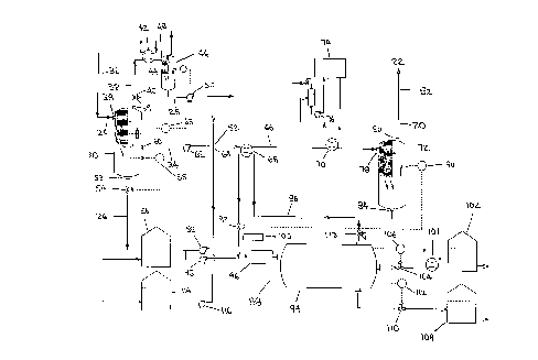
Figure 1 is a schematic drawing of a preferred embodiment of the
apparatus of the within invention, in which the vapor is comprised of steam
generated from produced water from a production well;
Figure 2 is a schematic drawing of a first alternate embodiment of the
apparatus of the within invention, in which the vapor is comprised of
hydrocarbon
vapor generated from light hydrocarbon liquid from a production well; and
Figure 3 is a schematic drawing of a second alternate embodiment of
the apparatus of the within invention, in which the vapor is comprised of a
mixture
or combination of steam generated from produced water and hydrocarbon vapor
generated from light hydrocarbon liquid from a production well.
DETAILED DESCRIPTION
Referring to Figures 1-3, the invention relates to a method and
apparatus for producing, from a liquid, a vapor (20) for injection into a well
(22). In
the preferred embodiment, the vapor (20) is produced at least in part using a
production fluid from a producing well. Most preferably, the production fluid
is
obtained from the same well into which the vapor is ultimately injected or
from a
production well associated or communicating with the well into which the vapor
is
injected.
The liquid from which the vapor (20) is produced may comprise any
substance in a liquid phase or condensed to a liquid phase which can readily
be
converted to vapor and which is capable of transferring an effective amount of
heat
to the well and thus the producing formation. In a typical production fluid,
suitable
liquids for use in producing the vapor in the within invention include
produced
wafer (26) and those hydrocarbons (24) which can be converted to vapor at the
temperature and pressure conditions of the method and apparatus. Such
hydrocarbons may be produced from a production well as either gases, liquids
or
condensates (such as gas condensates) and may be referred to as light
hydrocarbons.
_7_
CA 02233057 1998-03-24
In this disclosure, light hydrocarbon liquid refers to light hydrocarbons
which have
either been produced as a liquid phase or have been condensed to a liquid
phase.
Typical production wells produce hydrocarbons (24), produced water
(26) and solids. The produced water (26), is typically mixed with or entrained
in the
hydrocarbons (24). The solids may include particles of clays, metals,
silicates (such as
sand and silt), salt and other solid matter. The hydrocarbons (24) comprise a
wide
range of compounds, some of which are gases when produced and some of which
are liquids when produced. The gases are typically separated from the liquids
and
then either condensed for storage or transportation or burned or otherwise
vented
to the atmosphere. The liquids are typically stored or transported for further
processing. In this disclosure, the gases are described as hydrocarbon vapors,
the
liquids are described as crude oil, and the term production fluid includes
gaseous
and liquid hydrocarbons (24) and produced water (26) collectively. These
different
components of production fluid are seldom if ever pure, and each component may
contain amounts of one or more of the other components.
The vapor (20) is produced by the within invention for injection into a
conventional injection well (22) in a manner, and utilizing conventional
thermal
recovery methods and apparatuses, such that the vapor (20) acts to facilitate
the
production of hydrocarbons (24) from the injection well or from a well
associated or
communicating with the injection well (22). Conventional thermal recovery
methods for producing crude oil include cyclic steam injection, steam drive
and
steam assisted gravity drainage processes. The apparatus and process of the
within
invention may be used for the production of injection vapor for use with any
thermal recovery methods.
In the preferred embodiment of the invention, as shown in Figure 1,
the vapor (20) to be injected into the well (22) is generated substantially
from the
produced water (26) from the same well (22) or from a well associated or
communicating with the well (22). However, alternatively, as shown in Figures
2
and 3, the vapor (20) may be generated from light hydrocarbon liquid (28) from
the
well (22) or a well associated or communicating with the well (22), or from a
mixture or combination of both produced water (20) and light hydrocarbon
liquid
(28). Furthermore, the vapor (20) may be generated from a production fluid
from a
different well or from one or more wells. The process and apparatus parameters
for
_B_
CA 02233057 1998-03-24
each of these embodiments are substantially similar except where specifically
noted
herein.
Referring to Figures 1- 3, the apparatus is comprised of a production
fluid separator (30), which in the preferred embodiment is a free water
knockout
and degasser, for separating the production fluid from the well into a
produced
water phase comprising produced water (26), a hydrocarbon vapor phase
comprising
hydrocarbon vapor (32) and a crude oil phase comprising crude oil (34).
Specifically,
the production fluid passes through a line (36) from the well (22) or from a
well
associated or communicating with the well (22) and enters the production fluid
separator through an inlet (38).
Any form of three phase separator may be used as the production fluid
separator (30) in practicing the invention. In the preferred embodiment, the
inlet
(38) is packed with Pall (trade-mark) rings to calm the flow in the vessel and
provide
a coalescing medium to separate the gas from the liquids. The liquids fall to
the
bottom of the production fluid separator (30) where the crude oil phase
separates
from and floats on top of the produced water phase. In the preferred
embodiment,
the production fluid separator (30) is heated to a temperature of about
250°
Fahrenheit and is pressurized to a pressure of about 100 pounds per square
inch.
However, any suitable temperature and pressure compatible with both the
production fluid separator (30) and the temperature and pressure of the
production
fluid obtained from the well (22) may be used.
The hydrocarbon vapor phase and any water vapor included in the
heated production fluid exit the top of the production fluid separator (30)
through a
hydrocarbon vapor outlet (39) and pressure regulating valve (40) and are
conveyed
to a condenser (42) where condensible hydrocarbon vapor and water vapor are
condensed into light hydrocarbon liquid (28). The light hydrocarbon liquid
(28) and
any uncondensible vapor pass through a line (44) into a condensate separator
(46)
through an inlet (48) which is also packed with Pall (trade-mark) rings. In
the
condensate separator (46), uncondensible vapor exits the top of the condensate
separater (46) and is disposed of. A light hydrocarbon liquid pump (50)
controlled by
a liquid level controller pumps the light hydrocarbon liquid (28) either to a
light
hydrocarbon liquid reservoir (114) or directly to a mixer (52).
-9-
CA 02233057 1998-03-24
Produced water (26) which settles to the bottom of the production fluid
separator (30) is released from a produced water outlet (53) by a valve (54)
controlled
by an interface controller (55) either to a water reservoir (56) or is pumped
by a
produced water pump (58) directly to the mixer (52). A cooler (not shown) may
be
provided between the produced water outlet (53) and the water reservoir (56)
to cool
the produced water (26) so that it does not flash or boil in the water
reservoir (56).
Crude oil (34) is pumped from a crude oil outlet (60) in the production
fluid separator (30) to the mixer (52) by a crude oil pump (62) controlled by
a level
controller (63).
The amount of produced water (26) pumped by the produced water
pump (58) relative to the amount of crude oil (34) pumped by the crude oil
pump
(62) is determined by the desired vapor to oil ratio. The vapor to oil ratio
is the
optimum number of barrels of vapor that is required to be injected into the
well (22)
and thus the formation to result in the production from the well of one barrel
of
hydrocarbons (24). For most applications the vapor to oil ratio is
approximately 3:1
but is dependent upon the characteristics of the formation and of the
production
fluid.
In the event that the amount of produced water (26) included in the
production fluid of the well (22) is not sufficient to supply sufficient
produced water
(26) for use in the invention, then produced water (26) from other wells or
water
from other sources may be supplied to the water reservoir (56) as make-up
water.
The present invention involves combining a quantity of a liquid and a
quantity of an oil to produce a mixture of liquid and oil. In the embodiment
of
Figure 1, crude oil (34) as the oil and produced water (26) as the liquid are
combined
in the mixer (52). In the embodiment of Figure 2, crude oil (34) as the oil
and light
hydrocarbon liquid (28) as the liquid are combined in the mixer (52). In the
embodiment of Figure 3, crude oil (34) as the oil and both produced water (26)
and
light hydrocarbon liquid (28) as the liquid are combined in the mixer (52). In
all
three preferred embodiments, the mixer (52) comprises a junction (64) at which
point the oil and liquid are combined to produce the mixture. Other forms of
mixer
(52) may however be used. From the mixer, the mixture passes through a mixture
-10-
CA 02233057 1998-03-24
conduit (66) which in turn passes first through a preheating heat exchanger
(68) and
then through a heat exchanger (70). The preheating heat exchanger (68) is
optional.
One of the features of this invention is the preferred use of an indirect
heating system to heat the mixture of crude oil (34) and produced water (26),
crude
oil (34) and light hydrocarbon liquid (28) or crude oil (34), produced water
(26) and
light hydrocarbon liquid (28), as the case may be, in order to convert the
liquid to
vapor (20). The indirect heating is preferably accomplished by using
indirectly fired
heat exchangers rather than direct fired heat exchangers or other direct fired
heating
apparatus. The use of indirect heated heat exchangers results in reduced
temperature across the conduit conveying the mixture of crude oil (34) and
liquid
and may also reduce corrosion and scaling. By reducing scaling and eliminating
the
extreme high temperatures that result from direct firing, conduit rupture due
to
scale insulated hot spots is less likely to occur. Direct fired heat
exchangers or other
direct fired heating apparatus may, however, be used in the invention if care
is
taken.
'The preheating heat exchanger (68) and the heat exchanger (70) heat the
mixture of oil and liquid in order to produce a quantity of vapor from the
liquid.
The preheating heat exchanger partially heats the mixture by scavenging heat
from
crude oil (34) which is circulated through the preheating heat exchanger {68)
from a
vapor separator (72) located downstream. The heat exchanger (70) adds
sufficient
heat to turn substantially all of the liquid to vapor. The heat transferred to
the
mixture by the heat exchangers (68, 70) may also result in a portion of the
light
hydrocarbon liquid included in the crude oil (34) being turned to vapor.
The remaining crude oil (34) that is not vaporized serves to carry
undissolved solids and dissolved solids that are left behind by the liquid and
by the
light constituents of the crude oil (34) as they are turned to vapor. The
crude oil (34)
may also act as a corrosion inhibiter and scale inhibiter in the heat
exchangers (68,
70). In the preferred embodiment, the crude oil and vapor are heated to a
temperature of approximately 600°F depending on the pressure required
to inject
the vapor into the well. The higher the injection pressure the higher the
temperature must be in order to be above the saturation temperature of the
vapor.
-11-
CA 02233057 1998-03-24
In the preferred embodiment, heat is supplied to the heat exchanger
(70) by circulated heating oil. The heating oil is heated by a direct fired
once through
oil heater (74). The heating oil is preferably treated with corrosion
inhibiters. In the
oil heater (74), oxygen and other gases are removed and the closed. system is
blanketed with inert gas to prevent any other gas entry into the system. The
heating
oil is circulated by a heating oil pump (76). The heating oil is heated to
approximately 650°F by the oil heater (74). Heat may also be supplied
to the heat
exchanger (70) by other types of heaters and by circulating other types of
heating
fluids through the heat exchanger (70).
The heat exchangers (68, 70) are preferably multitube hairpin type heat
exchangers. Multitube hairpin tubes consist of a single finned tube enclosed
within
another tube. The heating fluid flows in the inner tube which has fins on its
external surface. The crude oil (34) and liquid to be heated flows in the
annular
space between the inner pipe and the outer pipe. There are a plurality of
these pipes
connected with hairpin turns to provide a long pipe system through which the
heating oil and the mixture to be heated pass. These tubes have been used in
oil
treating to evaporate water off crude oil without significant problems with
scaling,
corrosion or fouling.
In the preferred embodiment, all or substantially all of the liquid is
converted to vapor by passing the mixture through the heat exchangers (68,
70). In
conventional steam injection systems, a portion of the liquid is maintained in
its
liquid phase in order to carry the dissolved and undissolved solids which are
left
behind when the liquid is vaporized, and this unvaporized liquid is typically
injected into the well along with the vapor. As can be seen, this practice is
relatively
inefficient, since the full heat capacity of the liquid is not utilized. In
the present
invention, there is no need to maintain any of the liquid in its liquid phase
since
the crude oil (34) is intended to carry the dissolved and undissolved solids.
As a
result, in the preferred embodiment when the mixture has passed through the
heat
exchangers (68, 70), the mixture consists almost exclusively of crude oil
(34), minus
its very light constituents which have been vaporized, and vapor (20).
From the heat exchangers (68, 70), the mixture passes through the
mixture conduit (66) to an inlet (78) on the vapor separator (72). The vapor
separator (72) is a two phase separator which functions to separate the vapor
(20)
-12-
CA 02233057 1998-03-24
from the crude oil (34). Under normal conditions, a three phase separator is
not
required for the vapor separator (72) since there should be a negligible
amount of
water remaining in the mixture.
The inlet (~8) of the vapor separator (72) is packed with l~'all (trade
mark) rings to calm the flow and to provide a coalescing medium to separate
the
vapor from the crude oil. The vapor (20) exits the top of the vapor separator
(72)
through a vapor outlet (80) and is then injected into the well (22) through a
vapor
line (82). The crude oil (34) exits the bottom of the vapor separator (72)
through a
crude oil outlet (84).
It is desirable that the vapor (20) exit the vapor separator (72) at a
pressure sufficient to enable it to be injected into the well (22) and the
formation
without first undergoing additional pr essurization. For most applications, a
pressure of approximately 1500 pounds per square inch should be sufficient. In
order to achieve this pressure, it is preferable that the mixture, and in
particular the
vapor (20) be contained in the conduit (66) to inhibit expansion of the vapor
(20) in
the conduit (66) and that the combining of the crude oil (34) and the liquid
in the
mixer (52) be performed at an elevated pressure. Furthermore, it is preferred
that
the vapor separator (72) be a pressure vessel so that the pressure of the
vapor (20) at
the vapor separator inlet (78) is substantially the same as the pressure of
the vapor
(20) at the vapor separator vapor outlet (80). In the preferred embodiment,
the
mixing step takes place at a pressure of about 1525 pounds per square inch
with the
assistance of pumps and this pressure is substantially maintained in the
conduit (66)
and in the vapor separator (72) so that the pressure of the vapor (20) at the
vapor
separator vapor outlet (80) is approximately 1500 pounds per square inch. At
this
pressure, the temperature required to create substantially 100% quality
slightly
superheated steam is about 600° Fahrenheit. If light hydrocarbon liquid
(28) is
included in the liquid, then a different temperature may be required to create
substantially 100% quality slightly superheated hydrocarbon vapor at this
pressure.
In the preferred embodiment, the crude oiI (34) then passes through a
recirculating conduit (86) back through the preheating heat exchanger (68)
where
heat from the crude oil (34) is transferred to the mixture that is also
passing through
the preheating heat exchanger (68), thus cooling the crude oil (34). From the
preheating heat exchanger (68), the crude oil (34) passes through the
recirculating
-13-
CA 02233057 1998-03-24
conduit (86) to an oil treater (88). A level controller (90) in the vapor
separator (72)
controls a dump valve (92) in the recirculating conduit (86) to control the
flow of
crude oil (34) to the oil treater (88).
Referring to Figure 2, it can be seen that where the liquid to be
vaporized in the within invention consists substantially of hydrocarbon liquid
such
as light hydrocarbon liquid (28), the oil treater (88) may not be required.
The reason
for this is that hydrocarbon liquid is unlikely to carry with it a significant
amount of
dissolved or undissolved solids, with the result that the solids content of
the crude
oil (34) is not increased significantly, which in turn means that the crude
oil (34) will
be in substantially the same condition it was in when originally produced from
the
well (22). The need for the oil treater (88) in the within invention will
therefore
depend upon the characteristics of the liquid to be vaporized.
In the preferred embodiment, the oil treater (88) comprises
conventional desalting apparatus and conventional desalting methods are used
to
remove the dissolved and undissolved solids from the crude oil (34) after the
vaporization of the liquid has taken place in the presence of the crude oil
(34). Other
apparatus and methods may however be used.
In the preferred embodiment, the oil treater (88) comprises an oil
desalter (94). The oil desalter (94) serves to remove dissolved and
undissolved
solids from the crude oil (34). This is achieved by standard desalting methods
used
in the industry. One method, as shown in Figure 1, involves the mixing in a
mixer
(96) of relatively fresh water, such as produced water (26) supplied by a
desalting
water pump (98), into the crude oil (34) to absorb dissolved and undissolved
solids
from the crude oil (34). The addii:ion of demulsifier (100) controls the
emulsification that occurs during the mixing process. The finer the emulsion
created the better the contact between the crude oil (34) and water and the
better the
transfer of dissolved and undissolved solids from the crude oil (34) to the
water.
However, the finer the emulsion the more difficult it can be to separate the
crude oil
(34) and water after this transfer of solids has taken place.
Separation of the "clean" crude oil (34) and "salty" water occurs by
gravity in the oil desalter (94). The clean crude oil (34) is passed through
an oil
cooler (101) and then released to a sales oil tank (102) through a dump valve
(104)
-14-
CA 02233057 1998-03-24
controlled by a level controller (106) in the oil desalter (94). The "salty"
water is
released to a salt water tank (108) through a dump valve (110) controlled by
an
interface level controller (112) in the oil desalter (94). Hydrocarbon vapor
or water
vapor which separates from the crude oil (34) is released from the oil
desalter (94)
through a desalter gas regulating valve (113).
Separation of the crude oil (34) and water, or desalting, is typically
carried out at temperatures in the range of 212°F to 300°F. The
amount of produced
water (26) which is mixed with the crude oil (34) in the mixer (96) depends in
part
upon the salinity of the produced water (26) and the amont of dissolved and
undissolved solids contained in the crude oil (34). In conventiona.I desalting
procedures, the amount of produced water that is added is typically in the
range of
about 10% by volume of the crude oil (34). In the desalting procedures
relating to
the present invention, the amount of produced water (26) which must be added
to
the crude oil (34) may be as high as approximately 30% by volume of oil, due
to the
relatively high amount of dissolved and undissolved solids which are likely to
be
contained in the crude oil (34) as a result of performing the method of the
within
invention. From the salt water tank (108), the "salty" water that is separated
from
the crude oil (34) in the oil desalter (94) may be disposed of in deep salt
water wells,
may be treated, or may be transported from the well site for disposal or
treatment.
From the sales oil tank (102), the "clean" crude oil (34) may be transported
for
processing. Optionally, all or a portion of the clean crude oil (34) may be
recycled to
the mixer (52).
Referring to Figure 2, in circumstances where the oil treater (88) is not
required, the crude oil recirculating conduit (86) may pass from the
preheating heat
exchanger (68) to the oil cooler (101) where the crude oil (34) is further
cooled, and
may then pass directly to the sales oil tank (102) controlled by the dump
valve (92)
and the level controller (90).
Referring to Figures 2 and 3, a light hydrocarbon liquid reservoir (114)
may be provided for storing light hydrocarbon liquid (28) which exits the
condensate
separator (46). The light hydrocarbon liquid pump (50) may then be used either
to
supply the light hydrocarbon liquid reservoir (114) or to supply the mixer
(52). Light
hydrocarbon liquid (28) may also be supplied to the mixer (52) from the light
-15-
CA 02233057 1998-03-24
hydrocarbon liquid reservoir (114) using a light hydrocarbon liquid reservoir
pump
(116).
If the amount of light hydrocarbon liquid (28) separated from the
production fluid on an ongoing basis is insufficient for use in the method,
then
light hydrocarbon liquid (28) may be supplied to the mixer from both the
condensate
separator (46) and the light hydrocarbon liquid reservoir (114). Light
hydrocarbon
liquid (28) may in turn be supplied to the light hydrocarbon liquid reservoir
(114)
either from production fluid or from some other source or sources.
-16-