Language selection

Search

Patent 2233199 Summary

Third-party information liability

Some of the information on this Web page has been provided by external sources. The Government of Canada is not responsible for the accuracy, reliability or currency of the information supplied by external sources. Users wishing to rely upon this information should consult directly with the source of the information. Content provided by external sources is not subject to official languages, privacy and accessibility requirements.

Claims and Abstract availability

Any discrepancies in the text and image of the Claims and Abstract are due to differing posting times. Text of the Claims and Abstract are posted:

  • At the time the application is open to public inspection;
  • At the time of issue of the patent (grant).
(12) Patent Application: (11) CA 2233199
(54) English Title: CONTAINER
(54) French Title: CONTENANT
Status: Deemed Abandoned and Beyond the Period of Reinstatement - Pending Response to Notice of Disregarded Communication
Bibliographic Data
(51) International Patent Classification (IPC):
  • B65D 43/16 (2006.01)
  • E05D 7/10 (2006.01)
  • E05D 11/00 (2006.01)
(72) Inventors :
  • LOFTUS, STEPHEN CLIVE (United Kingdom)
(73) Owners :
  • MCKECHNIE UK LIMITED
(71) Applicants :
  • MCKECHNIE UK LIMITED (United Kingdom)
(74) Agent: RICHES, MCKENZIE & HERBERT LLP
(74) Associate agent:
(45) Issued:
(22) Filed Date: 1998-03-26
(41) Open to Public Inspection: 1998-09-27
Availability of licence: N/A
Dedicated to the Public: N/A
(25) Language of filing: English

Patent Cooperation Treaty (PCT): No

(30) Application Priority Data:
Application No. Country/Territory Date
9706432.3 (United Kingdom) 1997-03-27

Abstracts

English Abstract


A container in which the lid 16 is attached to the body of the container
by a hinge arrangement. When the hinge arrangement is assembled, knuckles
30 on the lid 16 are interleaved with knuckles 20 formed along the upper edge
of the container walls. Each of the knuckles 20, 30 has an elongate bore formed
to receive a single hinge pin along the common line 22, 36. When the lid 16 is
closed, tab 34 projects through the socket 24 into the interior of the knuckle 20,
thereby preventing the hinge being pulled apart.


French Abstract

Contenant dont le couvercle (16) est rattaché au corps par un dispositif à charnières. Lorsque le dispositif à charnières est assemblé, des charnons (30) sur le couvercle (16) s'engagent entre les charnons (20) formés le long du bord supérieur des parois du contenant. Chaque charnon (20, 30) comporte un trou allongé formé de manière à recevoir une broche de charnière unique sur leur ligne commune (22, 36). Lorsque le couvercle (16) est fermé, la languette (34) fait saillie par un logement (24) à l'intérieur du charnon (20), ce qui empêche la charnière d'être séparée.

Claims

Note: Claims are shown in the official language in which they were submitted.

CLAIMS
1. A container comprising a lid attached to the body of a container by a
hinge arrangement which has first and second hinge leaves, there being
cooperating formations associated with the hinge arrangement which, at least
in one relative orientation of the hinge leaves, engage to prevent the leaves
being pulled apart.
2. A container according to claim 1, in which the cooperating portions are a
projection formed on one leaf and a corresponding socket formed on the other
leaf.
3. A container according to claims 1 or 2, in which the cooperating
formations engage when the lid is closed, to prevent access to the interior of the
container through pulling apart of the hinge arrangement.
4. A container according to any preceding claim, in which the hinge
arrangements comprise knuckles formed on the leaves and interleaved to
receive a hinge pin.
5. A container according to claim 4, in which the cooperating formations
are surfaces of, or formed in, the knuckles.
6. A container according to any of claims 1 to 4, in which the cooperating
formations are remote from the hinge.
7. A container according to any preceding claim, in which the cooperating
formations incorporate arrangements which resist disengagement.
8. A container according to any preceding claim, in which the cooperating
formations comprise part cylindrical surfaces centred in the hinge axis and
turning into alignment and engagement as the hinge leaves move relative to
each other.

9. A container substantially as described above with reference to the
accompanying drawings.
10. Any novel subject matter or combination including novel subject matter
disclosed herein, whether or not within the scope of or relating to the same
invention as any of the preceding claims.

Description

Note: Descriptions are shown in the official language in which they were submitted.


CA 02233199 1998-03-26
.... 1
Container
The present invention relates to containers and in particular to lidded
containers.
Reusable delivery containers of synthetic plastics material are used for
many purposes, including delivery of goods to retail premises. A common size
for such containers is 600mm long and 400mm wide. Some of these containers
have lids, which may be hinged to the container body. A known design of
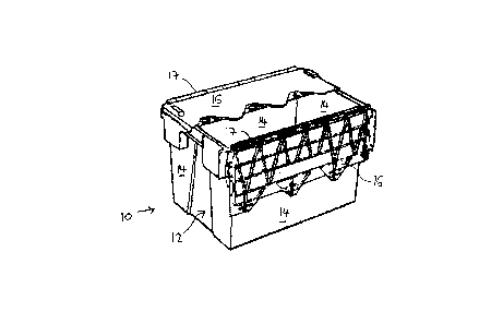
hinged lid container is shown in Fig. 1.
The container 10 has a body 12 consisting of a base (not shown) and four
upstanding walls 14. Two lid portions 16 (one of which is shown open) are
hinged to the walls 14 along the top edges 17 to open or close the container.
The hinges are formed by a line of knuckles on a lid portion, interleaved with aline of knuckles formed along the top edge of a wall, the two sets of knuckles
being connected either by a hinge pin extending through the line of interleaved
knuckles, or by the knuckles snap-fitting together.
The lid portions 16 interengage when the lids are closed.
Containers like that shown in Fig. 1 are used for many security
applications, primarily for security against pilfering of retail goods. The lidscan be sealed shut, such as by a security tag or lock. However, it has been
found that in known designs, external forces applied to the hinges, for instanceby levering or prising the lids away from the body, can cause damage to the
hinges, including breaking or distorting the hinge pin, which then allows the
lids to be removed easily from the box. Arrangements in which the hinge pin is
plastic are particularly prone to such failure.
It is an object of the present invention to provide an improved container.
According to the invention, there is provided a container comprising a lid

CA 02233199 1998-03-26
attached to the body of a container by a hinge arrangement which has first and
second hinge leaves, there being cooperating formations associated with the
hinge arrangement which, at least in one relative orientation of the hinge
leaves, engage to prevent the leaves being pulled apart.
The cooperating portions may be a projection formed on one leaf and a
corresponding socket formed on the other leaf.
Preferably the cooperating formations engage when the lid is closed, to
prevent access to the interior of the container through plllling apart of the
hinge arrangement.
The hinge arrangements may comprise knuckles formed on the leaves
and interleaved to receive a hinge pin. The cooperating formations may be
surfaces of, or formed in, the knuckles. Alternatively, the cooperating
formations may be remote from the hinge. The cooperating formations may
incorporate arrangements which resist disengagement.
The cooperating formations may comprise part cylindrical surfaces
centred in the hinge axis and turning into ~lignment and engagement as the
hinge leaves move relative to each other.
One arrangement according to the present invention will now be
described in more detail, by way of example only, and with reference to the
accompanying drawings in which:
Fig. 1 is a perspective view of a known container;
Fig. 2 is a partial elevation of the hinge leaf formed along the top of a
container wall, viewed from within the container;
Fig. 3 is a partial plan view of a hinge leaf formed along one edge of a lid
portion;

CA 02233199 1998-03-26
Figs.4 to 7 are vertical sections through the assembled hinge, viewed
along the hinge axis; and
Figs. 8 and 9 are vertical sections between two knuckles of an alternative
hinge arrangement.
Figs. 2 to 7 show aspects of a modified hinge arrangement according to
the present invention, for use in a container which is otherwise as shown in Fig.
1.
One leaf of the hinge between the container body and the lid is forrned as
a series of upstanding knuckles 20 along the upper edge of the container walls
and each having an elongate bore forrned to receive a hinge pin along the line
22 in Fig. 2. Each knuckle 20 also has a slot or socket 24 formed through its
wall, below the normal centre line 22 of the hinge pin. Adjacent knuckles 20
are separated by spaces 26.
The lid 16 is formed with a line of knuckles 30, adjacent knuckles being
separated by a space 32 in which a projection in the form of a tab 34 is located.
The knuckles 30 are, like the knuckles 20, pierced by elongate bores for receiptof a hinge pin along the line 36. The dimensions of the tab 34 are such as to
allow it to be received in a socket 24, as will be described.
When the hinge arrangement is assembled, knuckles 30 are interleaved
with knuckles 20 and a single hinge pin (which may be of metal or plastics) is
threaded through the aligned bores through the knuckles, along the common
line 22,36. Figs.4 to 7 show the hinge assembled in this manner.
Fig. 4 shows the lid 16 partially closed. The hinge pin 38 is captured in
the line of knuc~les, allowing hinging. The tab 34 is clear of the socket 24 by
virtue of the relative angles of the container body and lid. As the lid continues
to close, a relative angle is reached (Fig. 5) at which the tab 34 begins to enter
the socket 24. The fully closed position is illustrated in Fig. 6, with the tab 34

CA 02233199 1998-03-26
projecting through the socket 24 into the interior of the knuckle 20, projectingsubstantially beyond the walls of the socket 24.
Fig. 7 shows the situation if an attempt is made to force access to the
container by pulling apart the hinge arrangement just described. If the lid is
forced up in a mAnner which could darnage the hinge pin 38, the knuckles 30
will rise relative to the knuckles 20 as shown, but so too the tab 34 rises relative
to the socket 24. By appropriate dimensioning of the tab and socket, the
arrangement can ensure that the tab 34 abuts the upper wall of the socket 24 to
prevent further upward movement before the hinge pin has been distorted
unacceptably or at all. This is the position reached in Fig. 7. No further upward
movement of the lid is possible relative to the container body, because of the
engagement between the tab 34 and the socket 24. The hinge pin and thus the
integrity of the hinge is therefore assured.
Tt is to be appreciated that movement in the perpendicular direction (in
the plane of the lid portion 16) is not possible by virtue of engagement betweenthe two lid portions where they meet.
In an alternative (not shown) the tab 34 could be shaped to reach down
below the hinge and engage with a socket formed further down the container
wall. In either alternative, the tab could be barbed, or otherwise formed to
resist removal of the tab from the socket, thereby further enhancing security.
Figs. 8 and 9 show a further alternative. Knuckles 50 on the walls carry
cylindrical extensions 52, centred on the axis of the hinge pin 54. Further
cylindrical extensions 56 are carried by knuckles (not shown) of the lid, and are
also centred on the hinge pin 54. Consequently, the extensions 52,56 turn
relative to one another as the lid is opened and closed. With the lid open (Fig. 8)
they are away from each other, and the extensions 56 can pass through gaps 58
between extensions 52, to allow the hinge to be assembled and disassembled.
As the lid closes, the extensions reach the position of Fig. 9, where they overlie
each other and will abut to prevent the hinge being pulled apart.

CA 02233199 1998-03-26
It is envisaged that this arrangement could function without a hinge pin,
if appropriate arrangements are made to allow assembly but prevent unwanted
disassembly as the hinge turns.
It will be apparent that many variations and modificaffons can be made
to the arrangement described above without departing from the scope of the
present invention. In particular, the tab and socket could be reversed as
between the container body and lid, or could be moved to different positions in
the hinge. Other forms of interengaging formations could be used instead.
Interengagement could be provided at all, many or only some positions along
the line of the hinge, according to the degree of security required.
Whilst endeavouring in the foregoing specification to draw attention to
those features of the invention believed to be of particular importance it should
be understood that the Applicant claims protection in respect of any patentable
feature or combination of features hereinbefore referred to and/or shown in the
tlrawings whether or not particular emphasis has been placed thereon.

Representative Drawing
A single figure which represents the drawing illustrating the invention.
Administrative Status

2024-08-01:As part of the Next Generation Patents (NGP) transition, the Canadian Patents Database (CPD) now contains a more detailed Event History, which replicates the Event Log of our new back-office solution.

Please note that "Inactive:" events refers to events no longer in use in our new back-office solution.

For a clearer understanding of the status of the application/patent presented on this page, the site Disclaimer , as well as the definitions for Patent , Event History , Maintenance Fee  and Payment History  should be consulted.

Event History

Description Date
Inactive: IPC from MCD 2006-03-12
Application Not Reinstated by Deadline 2002-03-26
Time Limit for Reversal Expired 2002-03-26
Deemed Abandoned - Failure to Respond to Maintenance Fee Notice 2001-03-26
Inactive: Single transfer 1999-02-19
Application Published (Open to Public Inspection) 1998-09-27
Classification Modified 1998-07-30
Inactive: First IPC assigned 1998-07-30
Inactive: IPC assigned 1998-07-30
Inactive: Courtesy letter - Evidence 1998-06-16
Filing Requirements Determined Compliant 1998-06-10
Inactive: Filing certificate - No RFE (English) 1998-06-10
Application Received - Regular National 1998-06-08

Abandonment History

Abandonment Date Reason Reinstatement Date
2001-03-26

Maintenance Fee

The last payment was received on 2000-03-03

Note : If the full payment has not been received on or before the date indicated, a further fee may be required which may be one of the following

  • the reinstatement fee;
  • the late payment fee; or
  • additional fee to reverse deemed expiry.

Please refer to the CIPO Patent Fees web page to see all current fee amounts.

Fee History

Fee Type Anniversary Year Due Date Paid Date
Application fee - standard 1998-03-26
Registration of a document 1998-03-26
MF (application, 2nd anniv.) - standard 02 2000-03-27 2000-03-03
Owners on Record

Note: Records showing the ownership history in alphabetical order.

Current Owners on Record
MCKECHNIE UK LIMITED
Past Owners on Record
STEPHEN CLIVE LOFTUS
Past Owners that do not appear in the "Owners on Record" listing will appear in other documentation within the application.
Documents

To view selected files, please enter reCAPTCHA code :


To view images, click a link in the Document Description column. To download the documents, select one or more checkboxes in the first column and then click the "Download Selected in PDF format (Zip Archive)" or the "Download Selected as Single PDF" button.

List of published and non-published patent-specific documents on the CPD .

If you have any difficulty accessing content, you can call the Client Service Centre at 1-866-997-1936 or send them an e-mail at CIPO Client Service Centre.


Document
Description 
Date
(yyyy-mm-dd) 
Number of pages   Size of Image (KB) 
Abstract 1998-03-26 1 15
Description 1998-03-26 5 198
Claims 1998-03-26 2 43
Drawings 1998-03-26 4 43
Cover Page 1998-10-05 1 40
Representative drawing 1998-10-05 1 9
Filing Certificate (English) 1998-06-10 1 163
Request for evidence or missing transfer 1999-03-29 1 113
Courtesy - Certificate of registration (related document(s)) 1999-03-26 1 117
Reminder of maintenance fee due 1999-11-29 1 111
Courtesy - Abandonment Letter (Maintenance Fee) 2001-04-23 1 182
Correspondence 1998-06-16 1 29
Fees 2000-03-03 1 36