Note: Descriptions are shown in the official language in which they were submitted.
CA 02233401 1998-03-26
TITLE OF THE INVENTION
Cutting Tool for Mill:ing
BACKGROUND OF THE INVENTION
Field of the Invention
The present invention relates to a cutting tool for
milling having an insert of a cubic boron nitride sintered
body which is employed for milling cast iron components or
the like, and more particularly, it relates to a cutting
tool for milling such as a milling cutter or an end mill
which enables high-speed milling of cast iron components
with long life.
Description of the Prior Art
In general, cast iron components for automobile
engines or electrical appliances are face-milled or end-
milled with a high-speed steel tool, a cemented carbide
tool, a coated tool, a ceramics tool or a tool of a cubic
boron nitride (hereinafter referred to as CBN) sintered
body.
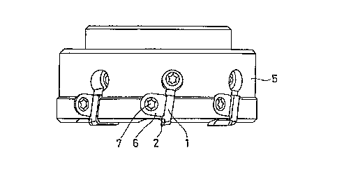
Figs. lA and lB show a face milling tool, to which
the present invention is applied. In this face milling
tool, a plurality of throwaway tips prepared by brazing
CBN sintered bodies 2 to only upper surfaces in the
vicinity of single ends of bases 1 consisting of cemented
carbide blocks are radially mounted on the outer periphery
of a cutter body 5 as shown in Fig. lB, with pressers 6
CA 02233401 1998-03-26
and clamp screws 7. In relation to such a face milling
tool, Japanese Patent Laying-Open No. 8-141822 (1996) in
the name of the assignee proposes a throwaway tip
consisting of a CBN sintered body and a cutter for milling,
which enables high-speed face milling of components
consisting of gray cast iron with long life by optimizing
the shapes of an insert, a minor insert, a negative land
etc. of the throwaway tip.
Cutting speeds V practically employed for face-
milling cast iron with a cemented carbide or coated tool
and a ceramics tool are about 150 to 250 m/min. and about
400 m/min. respectively. On the other hand, a CBN tool
which is excellent in wear :resistance and applicable to
high-speed cutting, such as the throwaway tip for milling
proposed in the aforementioned gazette, for example, is
capable of working cast iron at a cutting speed V of 500
to 1500 m/min. under a dry condition.
A cutting speed V practically employed for end-
milling cast iron with a high-speed steel, cemented
carbide or coated tool is about 30 to 100 m/min. On the
other hand, a CBN tool is capable of working cast iron at
a cutting speed V of 100 to 1500 m/min. under a dry
condition.
As hereinabove described, the CBN sintered body tool
is capable of face-milling cast iron at the cutting speed
CA 02233401 1998-03-26
V of 500 to 1500 m/min. under a dry condition. Under a wet
condition, however, the CBN sintered body tool is employed
at a practical cutting speed V within the range of 500 to
700 m/min. If the cutting speed V exceeds this range, the
insert of the CBN sintered body tool is heat-cracked to
remarkably reduce the tool :Life.
This is because the insert which is heated to an
extremely high temperature when coming into contact with
workpieces is rapidly quenched in slipping and heat-
cracked by the heat cycle applied thereto in case of
cutting cast iron at a high speed under a wet condition,
while the CBN sintered body, which has higher heat
conductivity and a lower thermal expansion coefficient as
compared with cemented carb:ide or ceramics, can withstand
thermal shock with small temperature difference in a heat
cycle under a dry condition.
As hereinabove described, the CBN sintered body tool
is capable of end-milling cast iron at the cutting speed V
of 100 to 1500 m/min. under a dry condition. Under a wet
condition, however, the CBN sintered body tool is employed
at a practical cutting speed V within the range of lO0 to
300 m/min. If the cutting speed V exceeds this range, the
insert is heat-cracked to remarkably reduce the tool life
similarly to the case of face milling.
It is conceived that t:he tool life is reduced under
CA 02233401 1998-03-26
a wet condition since the heat conductivity of the
conventional CBN sintered body is less than 400 W/m-K
under 20~C and a remarkable temperature gradient is caused
in the vicinity of its cutt.ing edge and high tensile
stress is applied to the insert in quenching with respect
to the temperature difference in the heat cycle under the
wet condition due to the low heat conductivity even if the
thermal expansion coefficient exceeds 4.0 x 10 6/K in the
temperature range of 20~C to 600~C, and heat cracking
readily results from repetition of remarkable expansion
and contraction due to the :high thermal expansion
coefficient.
If the cutting speed V of the CBN sintered body tool
is increased under a wet co:ndition similarly to that under
a dry condition, the tool life is unpreferably reduced to
increase the working cost i:n both of face milling and end
milling. Therefore, the CBN sintered body tool must cut
workpieces which are remarkably deformed or distorted by
heat generated in cutting o.r components to be protected
against even the slightest deformation caused by heat
generated in cutting under a dry condition or at a low
cutting speed V causing no :heat cracking under a wet
condition.
However, various types of machining equipment
rotatable at a high speed are recently developed one after
CA 02233401 1998-03-26
another, and high-speed cutt;ing is necessary and
inevitable for improving wor-king efficiency. In relation
to such machining equipment, therefore, awaited is
provision of an insert tool capable of coping with dry
working for suppressing influence exerted on workpieces by
increase of the cutting temperature.
While automobile engine components or the like may
be milled under a dry condit.ion, the working is performed
under a condition identical to the wet condition is a pre-
step includes wet working such as rough working orperforation due to a cutting fluid remaining on the
working spots, and hence the insert of the tool is still
heat-cracked and hence sufficient life cannot be obtained
in this case.
SUMMARY OF THE I NVENT I ON
An object of the present invention is to provide a
cutting tool for milling which can attain sufficient tool
life particularly in high-speed face milling under a wet
condition at a cutting speed V of at least 800 m/min. and
in high-speed end milling under a wet condition at a
cutting speed V of at least 300 m/min.
In order to attain the aforementioned object, the
cutting tool for milling according to the present
invention comprises an insert consisting of a cubic boron
nitride sintered body having heat conductivity of at least
CA 02233401 1998-03-26
400 W/m-K at 120~C and a thermal expansion coefficient
within the range of at least 3.0 x 10 6/K and not more than
4.0 x 10 /K in the temperature range of 20~C to 600~C.
It is inferred that the inventive sintered body tool
having such a structure attains long life in high-speed
milling under a wet condition for the following reason:
In a conventional CBN sintered body tool which is
applicable to milling, the CBN sintered body forming its
insert has heat conductivity of less than 400 W/m-K at
20~C and a thermal expansion coefficient exceeding 4.0 x
10 6/K in the range of 20~C to 600~C. Under a dry
condition, the sintered body can withstand thermal shock
since its cutting edge is not rapidly quenched and hence
temperature difference in a heat cycle is small. Under a
wet condition, however, a remarkable temperature gradient
is caused in the vicinity of the cutting edge and high
tensile stress is applied to the insert in quenching due
to large temperature difference in the heat cycle and high
heat conductivity. Further, it is conceived that heat
cracking is readily caused by repetition of remarkable
expansion and contraction due to the high thermal
expansion coefficient.
In the inventive cutting tool for milling, the heat
conductivity of the CBN sintered body forming the insert
is at least 400 W/m.K and the thermal expansion
CA 02233401 1998-03-26
coefficient is within the range of at least 3.0 x 10 6/K
and not more than 4.0 x 10 ~;/K in the range of 20~C to
600~C, whereby heat generated when the insert comes into
contact with workpieces in :high-speed milling can
efficiently escape to the overall sintered body. Further,
thermal expansion of the si:ntered body is small in the
vicinity of the insert and the heat moves toward the
overall sintered body as described above, whereby a
temperature gradient caused between the insert and the
interior of the sintered body is so small that tensile
stress resulting from thermal expansion difference is
reduced. Thus, it is conceivable that the insert is
subjected to small tensile stress when rapidly quenched
with a cutting fluid in slipping, and thermal shock
serving as the main factor :for heat cracking can be
reduced.
The heat conductivity of the cubic boron nitride
sintered body forming the insert is more preferably at
least 600 W/m.K at 120~C.
The cubic boron nitride content of the cubic boron
nitride sintered body forming the insert is preferably at
least 99 volume %. This is because the aforementioned
thermophysical values can be attained by increasing the
content of CBN, having the highest heat conductivity after
that of diamond and a low thermal expansion coefficient,
CA 02233401 1998-03-26
to at least 99 volume % for reliably attaining desired
thermophysical properties.
In milling, no desired effect can be attained if the
insert is chipped by mechanical impact force when coming
into contact with any workpiece from a slipping state due
to insufficient mechanical strength. The mechanical
strength can be improved by preparing the CBN sintered
body from CBN grains of 0.01 to 1.0 ~m in grain size and
increasing contact areas of these CBN grains for ensuring
the effect of suppressing chipping.
The transverse rupture strength of the CBN sintered
body forming the insert of the inventive cutting tool for
milling is preferably at least 80 kgf/mmZ, in
consideration of chipping resistance against mechanical
shock.
In application to a m:illing cutter for face milling,
the inventive cutting tool :Eor milling is employed under a
wet condition at a cutting speed V of at least 800 m/min.,
to be capable of attaining :Long life, which can be
attained by the conventiona:L CBN tool under a dry
condition. In application t;o an end mill, on the other
hand, the inventive cutting tool for milling is employed
under a wet condition at a cutting speed V of at least 300
m/min., to be capable of attaining long life, which can be
attained by the conventiona:L CBN tool under a dry
CA 02233401 1998-03-26
condition.
In the inventive cutting tool for milling, as
hereinabove described, the insert is prepared from the CBN
sintered body having the heat conductivity and the thermal
expansion coefficient within the prescribed ranges
respectively, while the CBN grain size and the transverse
rupture strength thereof are also in the prescribed ranges
respectively. Thus, the inventive cutting tool for milling
suppresses chipping resulting from heat cracking, can
extend the tool life in wet face milling at the cutting
speed V of at least 800 m/min. or at least 1000 m/min. and
in wet end milling at the cutting speed V of at least 300
m/min. or at least 500 m/min., and can remarkably improve
productivity in high-speed milling of components
consisting of gray cast iron under a wet condition, in
particular.
The foregoing and other objects, features, aspects
and advantages of the present invention will become more
apparent from the following detailed description of the
present invention when taken in conjunction with the
accompanying drawings.
BRIEF DESCRIPTION OF THE DRAWINGS
Figs. lA and lB are a plan view and a front
elevational view of a conventional face milling cutter
employing throwaway tips.
CA 02233401 1998-03-26
DESCRIPTION OF THE PREFERRED EMBODIMENTS
(Example 1)
Cutting tool samples Nos. 1 to 10 were prepared with
inserts of CBN sintered bodies having physical values
shown in Table 1 respectively, and subjected to a milling
test for plates (100 by 150 mm in section) of gray cast
iron FC250 with face milling cutters. The samples Nos. 1
to 5 are inventive, and the samples Nos. 6 to 10 are
comparative. With reference to each sample, Table 1 shows
heat conductivity at 120~C, a thermal expansion
coefficient in the temperature range of 20~C to 600~C, and
transverse rupture strength in three-point bending
measurement at a span of 4 mm. The milling test was
performed under the following cutting conditions:
V = 800 m/min.
d = 0.5 mm
f = 0.15 mm/edge
Table 1 shows the results of the test.
-- 10 --
Table 1
Conductivity E CBN ContentCBN Grain Size Rupture Cuttable
No.(W/m.li) (~10-~ ) (vol.%) (~lm) (l~,ef/mm2) cPOausnst
~20 3.7 98.5 0.05 - 0.5 80 dry 180
wet 95
2 450 3.G 99.3 0.5 - 3.0 75 dry 85
wet 90 D
Inventive 3 600 3.5 99.1 0.1 - 1.0 85 dry 180 ~,
Sample wet 180 ~
4 G50 3.5 99.8 0.5 - 2.0 80 dry lG5 1-
wet 140 1-
650 3.G 99 7 0 1 - 1 0 85 dry 190
wet 180 O
G ~20 4.2 97.5 0.1- 1.0 80 dry 170 ~,
wet 25
7 6.50 ~.2 98.2 2.3 - 3.0 65 dry 2
wet 2
Comparative 8 220 5.1 70 0.5 - 3.0 110 dry 170
Sample wet 0
9 3G0 4.0 85 0.5 - 3.0 110 dry 200
wet 12
3G0 3.7 95 0.5 - 2.0 100 dry 180
wet 10
CA 02233401 1998-03-26
As understood from Table 1, each of the inventive
cutting tool samples Nos. 1 to 5 exhibited heat
conductivity of at least 400 W/m-K at 120~C and a thermal
expansion coefficient within the range of at least 3.0 x
10 6/K to 4.0 x 10 6/K in the temperature range of 20~C to
600~C, and attained a high cuttable pass count under a wet
cutting condition.
In the comparative culting tool samples Nos. 6 to 10,
on the other hand, the tool life of the sample No. 6 was
remarkably reduced with a cuttable pass count of 25 under
a wet cutting condition whiLe that under a dry cutting
condition was 170. This is conceivably because heat
cracking was readily caused due to repetition of
remarkable expansion and contraction under the wet cutting
condition resulting from the thermal expansion coefficient
exceeding 4.0 x 10 6/K in the temperature range of 20~C to
600~C, although the heat conductivity of the cutting tool
sample No. 6 was in excess of 400 W/m-K at 120~C.
Further, the tool life of the comparative cutting
tool sample No. 7 was extremely short under both dry and
wet conditions, despite the high heat conductivity of 650
W/m-K at 120~C. This is conceivably because heat cracking
was readily caused due to the thermal expansion
coefficient exceeding 4.0 x 10 6/K in the temperature range
of 20~C to 600~C and the mechanical strength was reduced
- 12 -
CA 02233401 1998-03-26
due to the large CBN grain size exceeding 2.0 ~Lm.
The comparative cutting tool sample No. 8, which was
capable of cutting workpieces 170 times under a dry
cutting condition, was chipped ln single cutting under a
wet cutting condition, to exhibit extreme difference
between the dry and wet conditions. This is conceivably
because the heat conductivity of the sample No. 8 was
extremely lower than 400 W/m-K, the thermal expansion
coefficient was at a high level of 5.1 x 10 6/K in the
temperature range of 20~C to 600~C, and the CBN content was
at a low level of 70 volume %. The comparative cutting
tool samples Nos. 9 and 10 also exhibited extreme
difference between dry and wet conditions, to substantiate
that the heat conductivity remarkably influences the tool
life under a wet cutting condition.
Observing the data of the inventive cutting tool
samples Nos. 1 to 5 in deta:il, it is recognized that the
cutting tool sample No. 1 exhibited slightly large
difference in tool life between the dry and wet conditions.
This is conceivably because the heat conductivity of the
sample No. 1 was slightly lower as compared with the
samples Nos. 2 to 5 due to the CBN content lower than 99
volume %. The tool life of the sample No. 2 was slightly
shorter as compared with the remaining inventive samples,
although the same hardly exhibited difference between the
CA 02233401 1998-03-26
dry and wet conditions. This is conceivably because the
transverse rupture strength of the sample No. 2 was
slightly reduced due to the relatively large CBN grain
size.
S (Example 2)
In relation to the samples prepared in Example 1, an
evaluation test was made by performing face milling under
the following conditions:
V = 1500 m/min.
d = 0.5 mm
f = 0.15 mm/rev.
Table 2 shows the results.
- 14 -
Table 2
Conductivity . CBN ContentCBN Grain Size Rupture Cuttable
No.(W/m.};) E pan.slon (vol.%) (~m) (l~f/mm~) cPOausnst
420 3.7 98.5 0.05 - 0.5 80 dry 220
wet 180
2 450 3.G 99.3 0.5 - 3.0 75 wet 40 D
Inventive dr 300 ~
3 600 3.5 99.1 0.1 - 1.0 85 Y
Sample wet 320 ~
a~ G50 3.5 99.8 0.5 - 2.0 80 dry 300 c',
wet 220 1-
G50 :3 ~ 9~ 7 0.1 - 1.0 85 dry 300
wet 350 O
G 420 42 97.5 0.1- 1.0 80 dreyt 15
7 G50 a~.2 98.2 2.3 - 3.0 G5 dry 0
wet 0
Comparative 8 220 5.1 70 0.5 - 3.0 110 dry 80
Sample wet 0
9 3G0 4.0 85 0.5 - 3.0 110 dry 300
wet 13
3G0 3 7 95 0 5 - 2 0 100 dry 300
wet 10
CA 02233401 1998-03-26
As understood from Table 2, the samples attained
results substantially similar to those in Example 1 as a
total tendency also in high-speed cutting at the cutting
speed V of 1500 m/min., although the cuttable pass counts
were different from those in Example l. It is inferred
that the influence by the transverse rupture strength
remarkably reflected on the difference of the cuttable
pass counts in Examples 1 and 2 due to the high-speed
cutting condition in Example 2.
(Example 3)
End mills were formed with inserts prepared from the
CBN sintered body samples employed in Example 1, and
subjected to a lateral cutting test for plates (100 by 150
. mm in section) of gray cast iron FC250 under the following
~5 cutting conditions:
V = 500 m/min.
Ad = 3 mm
Rd = 0.1 mm
f = 0.05 mm/edge
~0 Table 3 shows the results.
- 16 -
CA 02233401 1998-03-26
- ~ r' ~ ~ ~ ~ ~ ~ ~ ~ ~ ~ ~
~ $ 11~ 1~ C~~ $ oo ~ o~ g 0~o N cr~ N ~~ O COD O C-~~ ~
_ N ~ N ~ N _ N _ _~
~ ~ _ ~ . ~ ~ ~ ' 3 ~ 3 ~ 3 ~ 3 ~ ~
.o ~, -- c
o ~ ~ o ~ o ~o ~ ~ $
V? ~-,
c~
u~ O O O O O O O O O
r' ,~ o ~ ~ N -- -- ~ ~ ~ N
z o O O O O O N O O O
m
N o
m
_ r ,~
.
L
F~
. ~
- ~ o o o o o o o o o o
U
~ _ C'l C~ ~
a t,
s ; C,
.~ .
CJ
CA 02233401 1998-03-26
As understood from Table 3, the end mill samples
exhibited high cuttable pass counts as a whole in the
lateral cutting test for plates, due to the working mode
different from that in the face milling test. Relatively
comparing the samples with each other, it can be said that
the samples exhibited a tendency substantially similar to
those in Examples 1 and 2 as a whole in relation to the
tool life.
Although the present invention has been described
and illustrated in detail, it is clearly understood that
the same is by way of illustration and example only and is
not to be taken by way of limitation, the spirit and scope
of the present invention being limited only by the terms
of the appended claims.
- 18 -