Note: Descriptions are shown in the official language in which they were submitted.
CA 02233465 1998-03-27
- 1 -
97141 f9-77,116)
CERAMIC HONEYCOMB STRUCTURAL BODY
BACKGROUND OF THE INVENTION
[0001]
1. Field of the Invention
This invention relates to a ceramic honeycomb
structural body having a plurality of open-ended cells
defined by cell walls.
[0002]
2. Description of Related Art
A filter comprised of a ceramic honeycomb
structural body has been used from the old time as a
catalyst substrate or a fine particle filter used for
purifying an exhaust gas of an internal combustion engine,
or a filter used for purifying or deodorizing a combustion
gas from petroleum or various gases as a fuel. Fig. 4 is
a sectional view perpendicular to open-ended cells
illustrating an embodiment of the conventional ceramic
honeycomb structural body. In the embodiment of Fig. 4,
the ceramic honeycomb structural body 51 of a columnar
shape made from a material such as cordierite or the like
comprises a plurality of open-ended cells-53 defined by
cell walls 52 and extending in parallel to each other.
As a part of the open-ended cells 53 is enlargedly shown
in Fig. 5, all open-ended cells 53 in the conventional
ceramic honeycomb structural body 51 have, in many cases,
a square shape on a surface perpendicular to the
longitudinal direction of the open-ended cells 53, while
CA 02233465 1998-03-27
- 2 -
each of corner 53a has a right-angled shape crossing
surfaces of the cell walls 52 to each other.
[0003)
In the ceramic honeycomb structural body 51
particularly used as a catalyst substrate for the
purifying the exhaust gas of the internal combustion
engine, it is recently required to have thinner partition
cell walls 52 and a greater number of open-ended cells 53
so as to satisfy conditions such as an increase of
purification efficiency of the exhaust gas, a reduction of
pressure loss, use at a higher temperature and the like.
The ceramic honeycomb structural bodies having thinner
cell walls 52 in accordance with the aforementioned
requirement have such problems that the structural body is
liable to collapse due to thinner cell wall 52 and the
mechanical strength becomes low. And also, there are
problems that it is very difficult to manufacture a jig
(die) required for the production of the structural body
and the number of the manufacturing steps is large and it
is difficult to obtain the jig at a high working accuracy
and the cost and delivery time are increased, and the like.
Furthermore, even in the forming of the structural body,
it is important to prevent the collapse and deformation at
the forming step.
[0004]
In order to improve the mechanical strength of the
ceramic honeycomb structural body 51, there have hitherto
been known techniques disclosed in JP-A-54-110189 and
CA 02233465 1998-03-27
- 3 -
JP-A-54-150406. According to these techniques, the
thickness of the cell wall located at an outer peripheral
side of the ceramic honeycomb structural body 51 is made
thicker than that located at a central side thereof, but
there are caused problems that the thickening of the cell
wall 52 narrows an effective open-ended cell 53 and
increases the weight of the structural body to lower the
thermal shock resistance.
[0005]
Further, as a technique relating to four corner
parts 53a of each open-ended cell 53 in the ceramic
honeycomb structural body 51, there have been known
techniques disclosed in JP-A-49-113789 and JP-A-56-147637.
According to these techniques, a round or straight swollen
portion or fillet portion is disposed on each corner part
53a of all open-ended cells 53 in the ceramic honeycomb
structural body 51. In this case, however, there is a
problem that it is very difficult to manufacture a forming
jig used for producing the ceramic honeycomb structural
body 51 having thinner cell walls 52. This problem
becomes conspicuous when the thickness of the cell wall is
thinner (not more than 0.15 mm). Furthermore, there is
caused a problem that a rate.of lowering the mechanical
strength of the stnzctural body or causing the collapse in
the forming is increased.
SUMMARY OF THE INVF~1TION
[0006]
It is, therefore, an object of the invention to
CA 02233465 2000-07-21
64881-461
4
solve the aforementioned problems and to provide a ceramic
honeycomb structural body capable of providing a sufficient
mechanical strength even in the thinning of the cell wall and
lessening burden such as the manufacture of the forming jig or
the like.
[0007]
According to the present invention, there is provided
in a ceramic honeycomb structural body having a plurality of
open-ended cells defined by cell walls, the improvement wherein
a reinforcing portion is formed on each corner of an open-ended
cell existing in a second zone outside a first zone inclusive
of a center in a plane perpendicular to the open-ended cells,
wherein said reinforcing portion is in the form of a round or
straight-shaped fillet.
In a preferable embodiment of the invention, the
reinforcing fillet portion formed in each corner part of the
open-ended cell existing in the second zone defined as an outer
portion of the ceramic honeycomb structural body is round or
straight-shaped whereby the mechanical strength and shape
retention of the ceramic honeycomb structural body having thin
cell walls can be improved. The reason why each of the corner
parts of the open-ended cell existing in the second zone is
reinforced is due to the fact that compressive force is
frequently applied from an exterior in the handling of the
structural body or in use as a catalyst substrate and largely
acts on the outer peripheral
CA 02233465 2000-07-21
64881-461
- 5 -
portion of the ceramic honeycomb structural body.
[0009)
Further, the forming jig used for manufacturing
the ceramic honeycomb structural body of the above
S structure is manufactured by subjecting portions of the
jig corresponding to the cell walls to an electrospark
machining, placing electrodes at interconnected points of
these portions and then conducting an electrolytic
machining under given conditions to form portions
corresponding to the reinforcing portions in the corner
parts of the open-ended cell, preferably the round or
straight.-shaped fillet portions. For this end, if there
are many portions required for the formation of the round
or straight-shaped fillet portion, the number of the
manufacturing steps and the cost are increased and the
delivery time becomes long. In the invention, it is not
necessary to form the round or straight-shaped fillet
portion in each corner part of all open-ended cells, and
the round or straight-shaped fillet portion is merely
formed in each corner part of the open-ended cell existing
in the second zone, so that it is possible to decrease the
number of manufacturing steps of the forming jig and hence
reduce the cost and delivery time.
BRIEF DESCRIPTION OF THE DRAWINGS
The invention will be described with reference to
the accompanying drawings, wherein:
Fig. 1 is a schematically sectional view of an
embodiment of the ceramic honeycomb structural body
CA 02233465 1998-03-27
- 6 -
according to the invention;
Fig. 2 is an enlarged view of a part of the
structural body shown in Fig. 1;
Fig. 3 is a schematically sectional view of
another embodiment of the ceramic honeycomb structural
body according to the invention;
Fig. 4 is a schematically sectional view of an
embodiment of the conventional ceramic honeycomb
structural body; and
Fig. 5 is an enlarged view of a part of the
structural body shown in Fig. 4.
DESCRIPTION OF PREFERRED EMBODIMENTS
[0010]
In Fig. 1 is sectionally shown a first embodiment
of the ceramic honeycomb structural body according to the
invention in a direction perpendicular to open-ended cells
thereof. In the embodiment of Fig. 1, a ceramic honeycomb
structural body 1 of a columnar shape made from a material
such as cordierite or the like comprises a plurality of open-
ended cells 3 defined by interconnected walls or cell walls
2 and extending in parallel to each other. According to the
invention, in a plane perpendicular to the open-ended cells
3 shown in Fig. 1, the shape of the open-ended cell 3 exist-
ing in a first zone 4 inclusive of a center is rectangular
likewise the conventional one, while the open-ended cell 3
existing in a doughnut-shaped second zone 5 located
outside the first zone 4 is a rectangular shape provided
at each corner part thereof with a reinforcing portion,
CA 02233465 1998-03-27
preferably a round or straight-shaped fillet portion.
[0011]
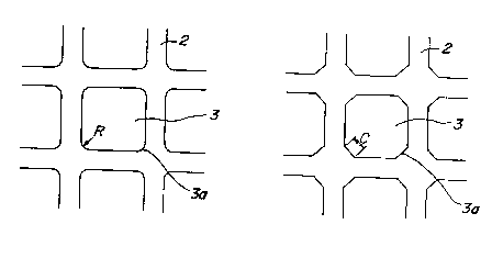
In Fig. 2 is enlargedly shown a part of the second
zone 5 shown in Fig. 1 illustrating the shape of the
reinforcing portion formed in the four corner parts
according to the invention. Fig. 2a is a case showing a
round shape, wherein the open-ended cell 3 is a
rectangular shape in a plane perpendicular to the open-
ended cells and at the same time each of four corner parts
3a as an interconnected point of the rectangle has a round
shape having a radius of curvature R. Fig. 2b is a case
showing a straight shape, wherein the open-ended cell 3 is
a rectangular shape in a plane perpendicular to the open-
ended cells and at the same time each of four corner parts
3a as an interconnected point of the rectangle is
reinforced with a straight-shaped reinforcing portion
having a width C.
[0012]
In the embodiment of Figs. 1 and 2, each of the
four corner parts 3a of the open-ended cell 3 is provided
with the reinforcing portion, preferably the round or
straight-shaped reinforcing portion, so that there can
easily be formed the ceramic honeycomb structural body
having thin cell walls 2 and a sufficient mechanical
strength. And also, the range of forming the reinforcing
portion in the corner part 3a is limited to the second
zone 5 located outside the first zone, so that the number
of the manufacturing steps for the jig required in the
CA 02233465 1998-03-27
_ g _
forming can be diminished and the reductions of the cost
in the manufacture of the jig and the delivery time can be
attained.
[0013]
Further, the round or straight shape in the corner
part 3a of the open-ended cell 3 hardly exerts upon the
hydraulic radius of the open-ended cell 3, so that there
is no increase of pressure loss in its use. Moreover, the
round or straight shape in the corner part 3a of the open-
ended cell 3 decreases a void portion of the corner part
3a, so that an amount of an expensive catalyst to be
supported on the surface of the cell wall can be decreased,
and as a result the cast of a final product can be reduced.
[0014]
Fig. 3 is a schematically sectional view of
another embodiment of the ceramic honeycomb structural
body according to the invention in a plane perpendicular
to the open-ended cells 3 likewise the case of Fig. 1.
In the embodiment of Fig. 3, the second zone 5 is divided
into two inner and outer sub-zones 5-1, 5-2 on a
concentric circle so as to make the size of the round or
straight shape in each corner part 3a of the open-ended
cell 3 existing in each of sub-zones 5-1 and 5-2 larger
toward the outer peripheral portion of the ceramic
honeycomb structural body 1. That is, the size of the
round or straight shape in the inner sub-zone 5-1 is made
smaller than that in the outer sub-zone 5-2. Of course,
the division number in the second zone is not limited to
CA 02233465 1998-03-27
_ g
be 2 and may be 3 or more. Even in the latter case, it is
needless to say that it is necessary to make the size of
the round or straight shape in each corner part 3a of the
open-ended cell 3 existing in each of the divided sub-
s zones larger toward the outer peripheral portion of the
ceramic honeycomb structural body 1.
[0015]
The following examples are given in illustration
of the invention and are not intended as limitations
thereof.
ale 1
A ceramic honeycomb structural body 1 of 100 mm in
diameter and 150 mm in length comprising a plurality of
open-ended cells 3 defined by cell walls 2 of 0.1 mm in
thickness and 1.27 mm in interconnected length is formed
by using a jig as sample Nos. 1-6 having a shape, a size
and a range of a corner part 3a as shown in Table 1. Then,
an influence based on the shape of the corner part is
examined by visually observing the presence or absence of
collapse in the forming of the ceramic honeycomb structural
body 1. The results are also shown in Table 1. As seen
from the results of Table 1, the sample Nos. 2-6 having
the round-shaped corner part 3a as an invention example
are not collapsed in the forming and can conduct the good
forming as compared with sample No. 1 as the conventional
example. Among the invention examples, it has been found
that the examples having a radius of curvature of the
round shape of not less than 0.05 mm are excellent.
CA 02233465 1998-03-27
- 10 -
[0016]
Table 1
Sample No. 1 2 3 4 5 6
Sha a of corner right
p part round round round round round
ogle
Size of corner part
0 0.03 0.05 0.10 0.15 0.20
(mm)
Range of second zone
(lengthfrom outer 25 25 25 25 25 25
periphery (mm) )
Collapse in forming x 0 O O O O
note) O: no collapse, D slight collapse,
x: collapse, fail as product
[0017]
Examola 2
A ceramic honeycomb structural body 1 having the
same size as in Example 1 as sample Nos. 11-15 is formed
by using a jig so as to change a length of a second zone 5
containing an open-ended cell 3 provided with a round-
shaped corner part 3a with a radius of curvature of 0.1 man
from an outer periphery of the structural body as shown in
Table 2. Then, an influence based on the existing range
of the second zone 5 is examined by visually observing the
presence or absence of collapse in the forming of the
ceramic honeycomb structural body 1. The results are also
shown in Table 2. As seen from the results of Table 2,
the sample Nos. 12-15 as the invention examples are not
collapsed in the forming and can conduct the good forming
as compared with sample No. 11 as the conventional example.
CA 02233465 1998-03-27
- 11 -
Among the invention examples, it has been found that the
examples having the length of the second zone 5 from the
outer periphery of the second zone of not less than 6 mm
are excellent.
[0018]
Table 2
Sample No. 11 12 13 14 15
Shape and size of round round round round round
corner part (mm) 0.1 0.1 0.1 0.1 0.1
Range of second zone
(length from outer 0 4 6 25 50
periphery (mm))
Collapse in forming x 0
[0019]
Examx~ 1 a 3
With respect to the sample Nos. 2-6 in Example 1
and the sample Nos. 12-15 in Example 2, the resulting
structural body is actually fired under the same condition
to form a fired body, and then the compression strength
and thermal shock resistance are measured with respect to
the fired body. The thermal shock resistance is evaluated
as follows. That is, a test specimen of the fired body
cooled to room temperature is placed in an electric
furnace held at a temperature of room temperature + 700°C
and kept at this temperature for 20 minutes and thereafter
taken out from the electric furnace and cooled to room
temperature. Then, the test specimen is considered as an
acceptable product only when no crack is observed and a
CA 02233465 1998-03-27
- 12 -
metallic sound is heard by striking the outer peripheral
portion of the specimen with a fine metal rod while
observing its appearance. Next, the same procedure as
described above is continued until the specimen as an
acceptable product becomes unacceptable while raising the
temperature inside the electric furnace every 50°C.
The thermal shock resistance is represented by a temperature
value obtained by subtracting room temperature from a
maximum temperature in acceptance. On the other hand, the
compression strength is a compression strength at breakage
when hydrostatic pressure load is isotropically applied to
the honeycomb structural body and is represented by a
pressure value when the breakage is caused. In any case,
the value of each property is an average when the number
of the specimen is five. The results are shown in Tables
3 and 4.
[0020]
Table 3
Sample No. 2 3 4 5 6
Size of round shape (mm) 0.03 0.05 0.10 0.15 0.20
Compression strength 5 68 92 103 120
(kg/cxn )
Thermal shock resistance 920 900 900 870 750
~ ~ ~ ~ ~
(C)
CA 02233465 1998-03-27
- 13 -
[0021]
Table 4
Sample No. 12 13 14 15
Range of second zone
( length from outer periphery (mm)4 6 25 50
)
Compression strength (kg/cm2) 5 68 92 103
Thermal shock resistance (C) I 900 900 900 900
I I I
[0022]
As seen from the results of Table 3, the sample
Nos. 3-6 having the size of the round shape of not less
than 0.05 mm are excellent in the compression strength as
compared with the sample No. 2 having the size of the
round shape of 0.03 mm. As seen from the results of Table
4, the sample Nos. 13-15 having the range of the second
zone of not less than 6 mm from the outer periphery are
excellent in both the compression strength and thermal
shock resistance as carnpared with the sample No. 12 having
the range of the second zone of 4 mm.
[0023]
The invention is not limited to the aforementioned
examples and various modifications and changes can be made.
For instance, although the reinforcing portion.formed in the
corner part is a round or straight shape, the other shape
thereof may be adopted as far as the purpose of reinforce-
ment can be attained. For example, a round shape convexly
extending toward the center of the open-ended cell 3 may
be used as opposed to the aforementioned round shape. And
also, although there is described the embodiment wherein
CA 02233465 1998-03-27
- 14 -
the second zone 5 is divided into plural sub-zones and the
size of the round or straight shape in each sub-zone is
made gradually and intermittently large from the center
toward the outer periphery, the similar result can be
obtained by gradually and continuously making large the
size of the round or straight shape of the corner part in
the second zone 5 as ,~ whole from the center toward the
outer periphery without dividing the second zone 5 into
sub-zones. F~zrthermome, although the sectional shape of
the open-ended cell i;~ described as a square, there may be
used, for example, triangle, rectangle, hexagon or a
combination thereof.
[0024]
As mentioned <~bove, according to the invention,
each corner part of the open-ended cell existing in the
second zone defined as an outer portion of the ceramic
honeycomb structural body is provided with the reinforcing
portion, preferably tree round or straight-shaped fillet
portion, so that the mechanical strength and shape
retention of the ceramic honeycomb structural body having
thin cell walls can beg improved. Furthermore, the
reinforcing portion i~, disposed in each corner part of the
open-ended cell existing in only the second zone without
disposing all corner parts of all open-ended cells, so
that it is possible to decrease the number of the
manufacturing steps for the forming jig and hence reduce
the cost and delivery time.