Language selection

Search

Patent 2234097 Summary

Third-party information liability

Some of the information on this Web page has been provided by external sources. The Government of Canada is not responsible for the accuracy, reliability or currency of the information supplied by external sources. Users wishing to rely upon this information should consult directly with the source of the information. Content provided by external sources is not subject to official languages, privacy and accessibility requirements.

Claims and Abstract availability

Any discrepancies in the text and image of the Claims and Abstract are due to differing posting times. Text of the Claims and Abstract are posted:

  • At the time the application is open to public inspection;
  • At the time of issue of the patent (grant).
(12) Patent Application: (11) CA 2234097
(54) English Title: A CONCENTRATOR PRESS
(54) French Title: PRESSE A EPAISSIR
Status: Deemed Abandoned and Beyond the Period of Reinstatement - Pending Response to Notice of Disregarded Communication
Bibliographic Data
(51) International Patent Classification (IPC):
  • B30B 9/24 (2006.01)
  • B01D 33/04 (2006.01)
  • D21C 9/18 (2006.01)
  • D21F 1/80 (2006.01)
(72) Inventors :
  • HODEN, EBBE (Sweden)
(73) Owners :
  • SUNDS DEFIBRATOR INDUSTRIES AB
(71) Applicants :
  • SUNDS DEFIBRATOR INDUSTRIES AB (Sweden)
(74) Agent: SMART & BIGGAR LP
(74) Associate agent:
(45) Issued:
(86) PCT Filing Date: 1996-10-03
(87) Open to Public Inspection: 1997-04-17
Availability of licence: N/A
Dedicated to the Public: N/A
(25) Language of filing: English

Patent Cooperation Treaty (PCT): Yes
(86) PCT Filing Number: PCT/SE1996/001249
(87) International Publication Number: WO 1997013572
(85) National Entry: 1998-04-06

(30) Application Priority Data:
Application No. Country/Territory Date
9503591-1 (Sweden) 1995-10-13

Abstracts

English Abstract


A concentrator press includes a pair of rotatble press rolls (1) which coact
with one another. The press rolls have apertured or perforated mantle surfaces
(5) for removing liquid from a liquid-drenched material (3) to be concentrated
and advanced between the press rolls. A part of the peripheral surface (5) of
each press roll (1), including at least those regions in which the press roll
acts on material undergoing concentration, is surrounded by a respective
endless filter-cloth web (6, 7) which also runs around at least one direction
changing roller (10; 10, 17, 18) at a distance from its associated press roll
(1) and the still not concentrated, liquid-drenched material (3). The filter-
cloth webs (6, 7) extend generally parallel with each other downstream of the
press nip, to a concentrated material delivery station (15, 16).


French Abstract

La présente invention concerne une presse à épaissir qui comprend deux rouleaux de presse rotatifs (1), qui coopèrent l'un avec l'autre. Leurs surfaces d'enveloppe (5) présentent des ouvertures ou des perforations pour éliminer le liquide d'une matière qui en est saturée (3) et qui doit être concentrée et déplacée vers l'avant entre les rouleaux de presse. Chacun de ces rouleaux (1) est entouré sur une partie de sa surface périphérique (5), y compris au moins au niveau des zones dans lesquelles il agit sur la matière en cours de concentration, par une bande sans fin de tissu filtrant (6, 7), qui passe aussi autour d'au moins un rouleau de renvoi (10; 10, 17, 18) situé à une certaine distance du rouleau de presse qui lui correspond (1) et de la matière trempée, non encore concentrée (3). Les bandes de tissu filtrant (6, 7) sont sensiblement parallèles en aval de la zone de pression, jusqu'à un poste de livraison (15, 16) de la matière concentrée.

Claims

Note: Claims are shown in the official language in which they were submitted.

5
CLAIMS
1. A concentrator press comprising a pair of rotatably drivable
press rolls (1) which are arranged for mutual coaction and
which have apertured or perforated mantle surfaces (5) for removing
liquid from a liquid-drenched material (3) to be concentrated
and advanced between the press rolls, wherein each of
the press rolls (1) is embraced around a part of its periphery
(5), including at least the region where they act on the material
undergoing concentration, by an endless filter-cloth web
(6, 7) which also runs around at least one web direction changing
roller (10; 10, 17, 18) located at a distance from an associated
press roll (1) and the still not concentrated liquid-drenched
material (3), characterized in that the filter-cloth
webs (6, 7) downstream of the press nip run generally parallel
with each other to a concentrated material delivery station
(15, 16).
2. A press according to Claim 1, characterized in that the mutually
parallel running web sections extend upwards from the
press rolls (1).
3. A press according to Claim 2, characterized in that the mutually
parallel running web sections function to deliver the
concentrated material (14) to a material transporter (15) situated
above the press rolls (1).
4. A press according to Claim 3, characterized in that the upper
parts of the mutually parallel running web sections are
curved so as to deliver the concentrated material (14) to one
side of the press.
5. A press according to any one of Claims 1-4, characterized
in that each endless filter-cloth web (6,7) coacts with a
respective web-tensioning roller (12).

6. A press according to any one of Claims 1-5, characterized
by means (13) for washing the filter-cloth webs (6,7) in those
regions in which the webs are out of contact with concentrated
material or material to be concentrated.
7. A press according to any one of Claims 1-6, characterized
in that the press rolls (1) are provided with means (8) for
conducting liquid away from said rolls, said means preferably
being connected to a source of subpressure.
8. A press according to any one of Claims 1-7, characterized
in that the press rolls are partially immersed into a trough
(2) having an inlet (4) for material to be concentrated.
9. A press according to Claim 8, characterized in that the
interior of the trough (2) is sealed against the atmosphere and
is placed under overpressure.

Description

Note: Descriptions are shown in the official language in which they were submitted.


CA 02234097 1998-04-06
W O 97fl3572 PCTISE96101249
A CONCENTFU~TOR PRESS
The present invention relates to a concentrator press of the
kind which comprises a pair rotatably drivable press rolls
which are arranged for mutual coaction and which have apertured
or perforated mantle surfaces for removing liquid from a liq-
uid-saturated material to be concentrated and advanced between
the press rolls, wherein each of the press rolls is embraced
around a part of its periphery, including at least the region
in which the roll acts on the material undergoing concentra-
tion, by an endless filter-cloth web which also runs around at
least one web direction changing roller located at a distance
from its associated press roll and the not yet concentrated
liquid-drenched material.
Concentrator presses of the aforesaid kind are known from SU-A-
561 76~ and are used to increase the dry solid contents of liq-
uid-particle or liquid-fibre suspensions or liquid-rich parti-
cle pulps or fibre pulps, such as for de-watering cellulose
pulps, for instance. A large total hole area in the apertured
or perforated mantle surfaces of the press rolls is therefore
desirable from the aspect of capacity. The size of the perfora-
tions in the mantle surfaces of the rolls can be increased,
with subsequent improvement in the permeability of the rolls,
by using filter-cloth webs that prevent the undesirable passage
of particles or fibres, provided that this increase in the size
of the holes does not impair the support afforded to the filter
cloth. In the case of the press described in SU-A-561 765, the
filter-cloth webs move downwards and away from one another af-
ter passing through the press nip and the concentrated materialfalls down into an underlying material transporter. This diver-
gence of the webs downstream of the press nip results in a de-
crease in the degree of compression or compaction of the mate-
rial and there is an undesirable tendency for moisture or liq-
uid that has already been pressed from the material being drawnback from the interior of the press rolls by suction

CA 02234097 1998-04-06
W O 97/13S7Z PCT/SE96/01249
The object of the present in~ention is to provide a novel and
advantageous arrangement with which the aforesaid drawbacks are
avoided to at least a substantial extent.
~ith the intention of solving the aforesaid problems, it is
proposed in accordance with the present invention that in a
concentrator press of the kind defined in the introduction, the
filter-cloth webs are caused to run generally parallel with one
another downstream of the press nip, up to a concentrated mate-
rial delivery station. This arrangement avoids re-wetting of
the concentrated material to a large extent. Further improve-
ments are achieved in this respect in accordance with a pre-
ferred embodiment of the invention in which the mutually paral-
lel web sections extend upwards from the press rolls. Prefera-
bly, the upper parts of the mutually parallel web sections arecurved so as to deliver the concentrated material to one side
of the press. This further reduces the risk of re-wetting the
concentrated material and the material is obtained ln the form
of a coherent web of generally uniform thickness which can be
subjected to a subsequent additional concentration stage for
instance, in a simple and rational manner.
Other characteristic features of the invention and advantages
afforded thereby will be evident fro~ the dependent Claims and
also from the following description of preferred embodiments of
the invention given by way of example only.
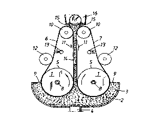
Figs. 1 and 2 are schematic vertical cross-section views of a
first and a second embodiment of an inventive concentrator
press respectively.
Those components and features that find ~utual correspondence
in the two Figures have been designated with the same reference
signs. The concentrator press illustrated in Fig. 1 includes
two press rolls 1 which are partially submerged in a trough 2,
which in the illustrated case is assumed to contain a pulp sus-
=, _ . . , ~ ,

CA 02234097 1998-04-06
PCT/SE96101249
W O 97/135~2
pension 3 that is to be concentrated or de-watered. The pulp
suspension is delivered through an inlet 4 with the aid of a
delivery pump, not shown.
The press rolls 1 typically include perforated or apertured
mantle surfaces 5 and are each partially embraced in the aper-
tured region thereof by a respective individual endLess filter-
cloth web 6, 7, e.g. a wire cloth of suitable plastic material.
As evident from Fig. 1, at least those parts of the mantle sur-
faces 5 of the rolls 1 that are immersed in the pulp suspensionare surrounded by an associated filter-cloth web. The roll
trunnions are journalled in the trough end walls, where at
least one trunnion 8 of each press roll is tubular and con-
nected to a pump or some other subpressure source (not shown)
for the purpose of removing liquid that has entered the inte-
rior of the rolls 1. Seals 9 act on the sides of the press
rolls 1 remote from the press nip between the rolls 1 in a re-
gion where the roll mantle surfaces are covered by an associ-
ated filter-cloth web 6, 7. Although not shown, corresponding
seals seal against the end surfaces of the rolls 1, so as to
close the trough 2 and enable a overpressure to be conveniently
maintained in the trough and therewith assist removal of liquid
from the pulp suspension 3 in the trough 2 and into the inte-
rior of the rolls 1.
Each of the filter-cloth webs 6, 7 partially surrounding the
rolls 1 runs around a web direction changing or guide roller
10. The filter-cloth webs move upwards from the roll nip to the
guide rollers 10 essentially parallel with one another in the
direction of the arrows 11. The reference numeral 12 identifies
web stretching or tensioning rollers that can be brought into
abutment with the webs 6, 7, whereas the reference numeral 13
identifies spray nozzles with which the webs are sprayed clean.
When the concentrator press shown in Fig. 1 is working, the
press rolls 1 are rotated in mutually opposite directions so
,

CA 02234097 1998-04-06
- W O 9711357Z PCT/SE96/01249
~,
that the mutually parallel sections of the webs 6, 7 will move
upwards at the same time as the pulp suspension is delivered to
the trough 2 under an overpressure and a subpressure is gener-
ated in the interior of the rolls 1. The suspension is there-
with drawn by suction towards those areas of the roll mantlesurface that are embraced by the filter-cloth webs and immersed
in the trough 2 and transported to and through the roll nip and
de-watered therein, wherewith water departs through the hollow
trunnions 8. The de-watered pulp 14 is transported upwards be-
tween the mutually parallel web sections to a delivery stationin which guide scrapers 15 lead the concentrated pulp into a
material transporter 16 situated above the press rolls 1 at a
distance therefrom. At least one press roll may be movable ta-
wards and away from the other so as to enable the size of the
press nip to be adjusted, and the filter-cloth webs 6, 7 may be
provided with conventional web restraining means (not shown)
for preventing lateral movement of the webs.
The embodiment illustrated in Fig. 2 corresponds essentially to
the Fig. 1 embodiment and will therefore be described below
solely with respect to the differences in the Fig. 2 embodl-
ment. In the Fig. 2 embodiment, the filter-cloth guide roller
10 is also movable in a vertical direction to enable tension in
the web 6 to be adjusted. Two direction changing rollers 17, 18
and a guide roller 19 are provided for the web 7, whereby the
web sections moving parallel with one another are curved to the
left in the Figure, such as to deliver the concentrated pulp 14
in the form of a coherent web of generally uniform thickness to
one side of the press. In this case, one of the direction
changing rollers 17, 18 is also movable generally horizontally
for adjusting the tension in the web 7.
The invention is not restricted to the aforedescribed and il-
lustrated exemplifying embodiments and can be implemented in
any desired manner that lies within the scope of the inventive
concept as defined in the following Claims.

Representative Drawing
A single figure which represents the drawing illustrating the invention.
Administrative Status

2024-08-01:As part of the Next Generation Patents (NGP) transition, the Canadian Patents Database (CPD) now contains a more detailed Event History, which replicates the Event Log of our new back-office solution.

Please note that "Inactive:" events refers to events no longer in use in our new back-office solution.

For a clearer understanding of the status of the application/patent presented on this page, the site Disclaimer , as well as the definitions for Patent , Event History , Maintenance Fee  and Payment History  should be consulted.

Event History

Description Date
Inactive: IPC from MCD 2006-03-12
Time Limit for Reversal Expired 2000-10-03
Application Not Reinstated by Deadline 2000-10-03
Deemed Abandoned - Failure to Respond to Maintenance Fee Notice 1999-10-04
Inactive: First IPC assigned 1998-07-13
Inactive: IPC assigned 1998-07-13
Classification Modified 1998-07-13
Inactive: IPC assigned 1998-07-13
Inactive: Notice - National entry - No RFE 1998-06-16
Application Received - PCT 1998-06-15
Application Published (Open to Public Inspection) 1997-04-17

Abandonment History

Abandonment Date Reason Reinstatement Date
1999-10-04

Maintenance Fee

The last payment was received on 1998-04-06

Note : If the full payment has not been received on or before the date indicated, a further fee may be required which may be one of the following

  • the reinstatement fee;
  • the late payment fee; or
  • additional fee to reverse deemed expiry.

Please refer to the CIPO Patent Fees web page to see all current fee amounts.

Fee History

Fee Type Anniversary Year Due Date Paid Date
Basic national fee - standard 1998-04-06
MF (application, 2nd anniv.) - standard 02 1998-10-05 1998-04-06
Registration of a document 1998-04-23
Owners on Record

Note: Records showing the ownership history in alphabetical order.

Current Owners on Record
SUNDS DEFIBRATOR INDUSTRIES AB
Past Owners on Record
EBBE HODEN
Past Owners that do not appear in the "Owners on Record" listing will appear in other documentation within the application.
Documents

To view selected files, please enter reCAPTCHA code :


To view images, click a link in the Document Description column. To download the documents, select one or more checkboxes in the first column and then click the "Download Selected in PDF format (Zip Archive)" or the "Download Selected as Single PDF" button.

List of published and non-published patent-specific documents on the CPD .

If you have any difficulty accessing content, you can call the Client Service Centre at 1-866-997-1936 or send them an e-mail at CIPO Client Service Centre.


Document
Description 
Date
(yyyy-mm-dd) 
Number of pages   Size of Image (KB) 
Abstract 1998-04-06 1 49
Description 1998-04-06 4 197
Claims 1998-04-06 2 60
Drawings 1998-04-06 1 24
Cover Page 1998-07-20 1 53
Representative drawing 1998-07-20 1 9
Notice of National Entry 1998-06-16 1 193
Courtesy - Certificate of registration (related document(s)) 1998-06-16 1 116
Courtesy - Abandonment Letter (Maintenance Fee) 1999-11-01 1 184
PCT 1998-04-06 7 255