Language selection

Search

Patent 2234295 Summary

Third-party information liability

Some of the information on this Web page has been provided by external sources. The Government of Canada is not responsible for the accuracy, reliability or currency of the information supplied by external sources. Users wishing to rely upon this information should consult directly with the source of the information. Content provided by external sources is not subject to official languages, privacy and accessibility requirements.

Claims and Abstract availability

Any discrepancies in the text and image of the Claims and Abstract are due to differing posting times. Text of the Claims and Abstract are posted:

  • At the time the application is open to public inspection;
  • At the time of issue of the patent (grant).
(12) Patent Application: (11) CA 2234295
(54) English Title: FLUID DISPENSING DEVICE
(54) French Title: DISPOSITIF DE DISTRIBUTION DE LIQUIDES
Status: Deemed Abandoned and Beyond the Period of Reinstatement - Pending Response to Notice of Disregarded Communication
Bibliographic Data
(51) International Patent Classification (IPC):
  • A45D 24/22 (2006.01)
  • A45D 19/00 (2006.01)
  • A45D 19/02 (2006.01)
  • A45D 24/24 (2006.01)
  • A46B 11/06 (2006.01)
(72) Inventors :
  • PAGLERICCIO, FERNANDO P. (Canada)
  • GIRARD, CHESTER F. (Canada)
(73) Owners :
  • FERNANDO P. PAGLERICCIO
  • CHESTER F. GIRARD
(71) Applicants :
  • FERNANDO P. PAGLERICCIO (Canada)
  • CHESTER F. GIRARD (Canada)
(74) Agent: MACRAE & CO.
(74) Associate agent:
(45) Issued:
(22) Filed Date: 1998-04-07
(41) Open to Public Inspection: 1999-10-07
Examination requested: 2003-02-06
Availability of licence: N/A
Dedicated to the Public: N/A
(25) Language of filing: English

Patent Cooperation Treaty (PCT): No

(30) Application Priority Data: None

Abstracts

English Abstract


A device for dispensing fluid is provided which evenly applies fluid products
to hair while the hair is being separated with the device. Combing is thereby
facilitated
and assisted by dispensing conditioner with the device. The device comprises a
head, a
plurality of teeth and a handle connected to the head. The teeth are removably
attached
to a front plate of the head. A shock absorber element provides an interface
between a
back plate of the head and the front plate. Flexibility of the front plate and
removability
of the teeth provide an improved combing/fluid dispensing device.


Claims

Note: Claims are shown in the official language in which they were submitted.

7
THE EMBODIMENTS OF THE INVENTION IN WHICH AN EXCLUSIVE
PROPERTY OR PRIVILEGE IS CLAIMED ARE DEFINED AS FOLLOWS:
1. A device for dispensing fluid comprising
a head defining a first hollow compartment therein, the head including a back
plate having a peripheral edge, a shock absorber element secured to the
peripheral edge,
a front plate secured to the shock absorber element;
a plurality of hollow teeth removably attached to the front plate, said teeth
having a plurality of holes, the first hollow compartment being in fluid
communication
with the hollow teeth; and
a handle connected to the head, said handle defining a second hollow
compartment for fluid storage, a first end of the second hollow compartment
being in fluid
communication with the first hollow compartment, a second end of the second
hollow
compartment having a removable stopper means, said handle having fluid
delivery means
for delivering fluid from the second hollow compartment to the first hollow
compartment.
2. The fluid dispensing device of claim 1, wherein the handle is constructed
of
pliable material such that fluid may be forced out of the second compartment
into the first
compartment by squeezing the handle.
3. The fluid dispensing device of claim 1, including pump means within said
handle for pumping fluid from the second compartment into the first hollow
compartment.
4. The fluid dispensing device of claim 1, wherein the teeth have six or more
holes.
5. The fluid dispensing device of claim 1, wherein the shock absorber element
comprises a layer of rubber.

8
6. The fluid dispensing device of claim 1, wherein
each tooth has a female end and
said head has a male portion such that the female end and the male portion are
matingly engageable.
7. The fluid dispensing device of claim 1, wherein each tooth has a threaded
end
and the head has compatible threaded sockets such that the teeth may be
screwed into the
head or screwed out of the head and replaced.
8. The fluid dispensing device of claim 1, further including a second set of
teeth
of different lengths being used to replace a first set of teeth.
9. The fluid dispensing device of claim 1, further including a second set of
teeth
having holes of different sizes being used to replace a first set of teeth.
10. A method of dispensing conditioner over the hair of a human head
comprising
the steps of:
(a) introducing fluid conditioner into the second compartment of the device
of claim 1;
(b) delivering fluid conditioner from the second compartment to the first
compartment and out through the holes in the teeth using the fluid delivery
means; and
(c) moving the device along the hair to separate hair strands using the teeth
while continuing to deliver fluid conditioner through the holes in the teeth,
such that fluid
conditioner is spread throughout the hair.

Description

Note: Descriptions are shown in the official language in which they were submitted.


CA 02234295 1998-04-07
1
FLUID DISPENSING DEVICE
This invention is related to a combination liquid dispenser and brush and in
particular to a device for use in applying hair conditioner.
Background
In conventional methods of shampooing and conditioning hair, fluid is
distributed from the container to the user's hand and then to the user's hair.
A selected
amount is applied to one area and subsequently spread over the rest of the
hair.
'There are a variety of hand-held combs that also apply liquid through the
comb. In fluid application the difficult problem is to effectively distribute
fluid to hair to
promote rapid detangling and removal of mans.
~U.S. Patent No. 4,229,116 (Moore) discloses a combination brush and liquid
soap dispenser which rotates to an open position. Moore does not permit
controlled liquid
dispensing; the rotary valve provides either an open or closed flow of fluid
and is thereby
not conducive to gradual dispensing of liquid with one hand on the brush.
There is a need
for a simplified tool for use with one hand to dispense fluid while combing
hair. The
device should not be any more difficult to operate than a standard comb or
brush.
LJ. S. Patent No, 4,294,270 (Cochran) discloses a fluid applicator. Although
the applicator may be used with one hand, the teeth structure defined therein
is stiff and
does not permit movement of the surface attached to the teeth. Use of this
applicator in
instances when hair is not already combed and detangled would be difficult and
painful
and promote pulling of the hair. There is a need for an improved fluid
dispensing tool
which encourages easy separation of hair strands as fluid is dispensed
thereto. In

CA 02234295 1998-04-07
2
particular a shock absorbing surface attached to the teeth is desired to
promote a forgiving
brushing or combing of hair, while still facilitating the gradual dispensing
of liquid
through the teeth holes. There is also a need for fluid dispensing devices
which are
compatible with various uses. In particular, removable teeth have heretofore
not been
available.
Summary of the Invention
The present invention utilizes an improved fluid dispensing tool to evenly
apply fluid products, including hair conditioners and shampoos. The general
purpose of
the present invention is to provide a simple tool consisting of a head with
two or more
teeth and a handle attached to the head.
The head includes a first hollow compartment that connects with a second
hollow compartment of the handle such that fluid stored in the handle may be
delivered
to the head and out through the teeth which are attached to one side of the
head. The
handle includes fluid delivery means for delivering fluid from the second to
the first
compartment. Removable stopper means contain fluid within the handle. The head
is a
mufti-piece unit including a rigid back plate having a peripheral edge and a
generally
concave wall, a flexible or resilient gasket or shock absorbing element
secured to the
peripheral edge, and a rigid front plate that somewhat mirrors the back plate
and is
secured to the gasket.
The front plate carries the teeth. The back plate is connected to the handle.
The teeth are' hollow and have a plurality of holes extending therethrough,
such that fluid
delivered to the head is evenly distributed from the teeth through these
holes. The teeth
are removable from the head and may be replaced with different teeth selected
by the

CA 02234295 1998-04-07
3
user. A user may select longer teeth or teeth with holes of different sizes
depending on
various factors including the selected fluid or hair type. The fluid
dispensing device of
this invention thereby permits easy conditioning and shampooing of hair with a
tool which
has a simple design and is easy to manufacture.
Brief Description of the Drawings
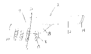
Figure 1 is a perspective view of a fluid dispensing device illustrating the
preferred embodiment of the invention;
Figure 2 is a bottom view of the device of Figure 1;
Figure 3 is an enlarged view of a tooth of Figure 1;
Figure 4 is a longitudinal cross-sectional view through the device of Figure
1; and
:Figure 5 is a cross-sectional view through lines 5-5 of Figure 1.
Description of the Preferred Embodiment
Figures 1 and 4 illustrate a fluid dispensing device 2 comprising a head 4
which forms or defines a hollow compartment 6. A plurality of hollow teeth 8
are
attached to the underside of the head. The teeth have a plurality of holes 10
extending
therethrough and are in direct communication with the hollow compartment of
the head.
A handle 12 is provided with one end attached to the head and the other end
closed with
a removable cap 14.
Figure 3 illustrates a preferred tooth structure 8. The too wall has a
plurality
of holes 10 directed therethrough which facilitate even distribution of the
fluid from the
hollow compartment of the head. The tooth base 16 is attached to a front plate
18 of the
head such that the tooth may be easily removed and interchanged with a tooth
of different

CA 02234295 1998-04-07
4
structure. Replacement teeth may have a different number or size of holes or
be of
varying rigidity or different lengths. In one embodiment each tooth has an
external thread
which may be screwed in and out of a threaded socket in the head. In another
embodiment each tooth has a female end which fits over a hollow raised boss on
the head.
Such connections may be threaded or smooth. This connection maintains its
integrity as
fluid passes from the compartment of the head to the teeth and out through the
plurality
of holes. In one embodiment the tooth base is made of plastic and the body 19
of the
teeth comprises rubber. The teeth are thereby flexible and work like fingers
to avoid
abrasion of the scalp upon contact.
As shown in Figures 4 and 5) the head includes a rigid concave back plate 20
having a peripheral edge 22, a flexible gasket or shock absorbing element 24
secured to
the peripheral edge, and a rigid front plate secured to the gasket. The front
plate carries
the teeth. The shock absorbing element may be made of rubber and permits
movement
of the teeth. In particular, the element allows the rigid front plate to have
some freedom
of movement relative to the back plate. In preferred embodiments this layer is
about ll4
inch wide. A check valve 26 may be located in the connection between the head
and the
handle. Fluid may be delivered from the compartment of the handle to the head
compartment in a variety of ways. The handle may be constructed of a pliable
material
whereby the handle is squeezed by the user to deliver material to the head
compartment
and then out through the teeth holes. Alternatively, a pump mechanism may
deliver
material from the handle compartment to the head compartment.

CA 02234295 1998-04-07
S
In Figures 1 and 2 the teeth are positioned in an alternating pattern on the
front plate of the head. The teeth may be normal to the front plate surface
(as shown in
Figures 4 and 5) or they may be at an acute angle to the normal to the
surface.
The device in accordance with the present invention may also be used in hair
colouring, tinting and similar procedures. The ability to customize the length
of teeth and
size of hole permits the user to modify the device according to the user's
particular needs.
In preferred embodiments the teeth of the invention have six or more holes
therethrough, permitting a more even distribution of fluid therefrom.
The subject invention also encompasses a method of dispensing fluid to human
or animal hair using the fluid dispensing device of Figure 1. A method of
dispensing fluid
and also combing hair using the device of Figure 1 is also contemplated. A
preferred
method provides the device of the subject invention to dispense conditioner
over human
hair and comb the conditioner evenly through the hair, thereby facilitating
effective
detangling and removal of matts.
1.5 ,A method of dispensing and combing conditioner includes depositing a
selected
amount of conditioner in the handle and securing the cap attached thereto,
then brushing
the hair with the fluid dispensing device such that the teeth separate the
hair strands.
While brushing the hair a user may also squeeze the handle to dispense
conditioner out
of the perforated teeth. Liquid is thereby spread evenly out on the hair
strands as the hair
is combed. Conditioner may be selectively dispensed more heavily in
particularly problem
areas that prove difficult to comb through.
The shock absorbing element facilitates the combing and dispensing action by
allowing gentle combing and spreading of teeth over the hair. This element
promotes easy

CA 02234295 1998-04-07
6
detangling with pain-free combing by allowing the front plate to bend about
the edge of
the back plate. The front plate may also be pushed or pulled toward or away
from the
back plate. The gasket also allows easier removal of the teeth from the hair.
Increased
mobility of the teeth as a result of the shock absorbing element does not
translate into
increased movement of the head, thereby allowing a steady, even dispensing of
liquid
notwithstanding any movement of the teeth as allowed by the shock absorber
element.
The scope of the present invention is not intended to be limited by the
embodiments provided herein but rather is defined by the following claims.

Representative Drawing
A single figure which represents the drawing illustrating the invention.
Administrative Status

2024-08-01:As part of the Next Generation Patents (NGP) transition, the Canadian Patents Database (CPD) now contains a more detailed Event History, which replicates the Event Log of our new back-office solution.

Please note that "Inactive:" events refers to events no longer in use in our new back-office solution.

For a clearer understanding of the status of the application/patent presented on this page, the site Disclaimer , as well as the definitions for Patent , Event History , Maintenance Fee  and Payment History  should be consulted.

Event History

Description Date
Application Not Reinstated by Deadline 2007-04-26
Inactive: Dead - Final fee not paid 2007-04-26
Deemed Abandoned - Failure to Respond to Maintenance Fee Notice 2007-04-10
Deemed Abandoned - Conditions for Grant Determined Not Compliant 2006-04-26
Inactive: IPC from MCD 2006-03-12
Notice of Allowance is Issued 2005-10-26
Letter Sent 2005-10-26
Notice of Allowance is Issued 2005-10-26
Inactive: Approved for allowance (AFA) 2005-08-31
Letter Sent 2003-03-04
Request for Examination Requirements Determined Compliant 2003-02-06
All Requirements for Examination Determined Compliant 2003-02-06
Request for Examination Received 2003-02-06
Application Published (Open to Public Inspection) 1999-10-07
Inactive: Cover page published 1999-10-06
Inactive: Correspondence - Formalities 1999-07-05
Inactive: First IPC assigned 1998-07-23
Classification Modified 1998-07-23
Inactive: IPC assigned 1998-07-23
Inactive: Filing certificate - No RFE (English) 1998-06-18
Filing Requirements Determined Compliant 1998-06-18
Application Received - Regular National 1998-06-16

Abandonment History

Abandonment Date Reason Reinstatement Date
2007-04-10
2006-04-26

Maintenance Fee

The last payment was received on 2006-04-07

Note : If the full payment has not been received on or before the date indicated, a further fee may be required which may be one of the following

  • the reinstatement fee;
  • the late payment fee; or
  • additional fee to reverse deemed expiry.

Please refer to the CIPO Patent Fees web page to see all current fee amounts.

Fee History

Fee Type Anniversary Year Due Date Paid Date
Application fee - small 1998-04-07
MF (application, 2nd anniv.) - small 02 2000-04-07 2000-04-07
MF (application, 3rd anniv.) - small 03 2001-04-09 2001-03-19
MF (application, 4th anniv.) - small 04 2002-04-08 2002-03-12
Request for examination - small 2003-02-06
MF (application, 5th anniv.) - small 05 2003-04-07 2003-02-17
MF (application, 6th anniv.) - small 06 2004-04-07 2004-04-07
MF (application, 7th anniv.) - small 07 2005-04-07 2005-01-06
MF (application, 8th anniv.) - small 08 2006-04-07 2006-04-07
Owners on Record

Note: Records showing the ownership history in alphabetical order.

Current Owners on Record
FERNANDO P. PAGLERICCIO
CHESTER F. GIRARD
Past Owners on Record
None
Past Owners that do not appear in the "Owners on Record" listing will appear in other documentation within the application.
Documents

To view selected files, please enter reCAPTCHA code :


To view images, click a link in the Document Description column. To download the documents, select one or more checkboxes in the first column and then click the "Download Selected in PDF format (Zip Archive)" or the "Download Selected as Single PDF" button.

List of published and non-published patent-specific documents on the CPD .

If you have any difficulty accessing content, you can call the Client Service Centre at 1-866-997-1936 or send them an e-mail at CIPO Client Service Centre.


Document
Description 
Date
(yyyy-mm-dd) 
Number of pages   Size of Image (KB) 
Representative drawing 1999-09-28 1 4
Claims 1998-04-07 2 62
Abstract 1998-04-07 1 13
Description 1998-04-07 6 200
Drawings 1998-04-07 2 25
Cover Page 1999-09-28 1 27
Drawings 1999-07-05 2 25
Filing Certificate (English) 1998-06-18 1 162
Reminder of maintenance fee due 1999-12-08 1 111
Reminder - Request for Examination 2002-12-10 1 113
Acknowledgement of Request for Examination 2003-03-04 1 185
Commissioner's Notice - Application Found Allowable 2005-10-26 1 161
Courtesy - Abandonment Letter (NOA) 2006-07-05 1 166
Courtesy - Abandonment Letter (Maintenance Fee) 2007-06-05 1 176
Correspondence 1998-06-23 1 22
Correspondence 1999-07-05 3 52
Fees 2000-04-07 1 26