Language selection

Search

Patent 2234333 Summary

Third-party information liability

Some of the information on this Web page has been provided by external sources. The Government of Canada is not responsible for the accuracy, reliability or currency of the information supplied by external sources. Users wishing to rely upon this information should consult directly with the source of the information. Content provided by external sources is not subject to official languages, privacy and accessibility requirements.

Claims and Abstract availability

Any discrepancies in the text and image of the Claims and Abstract are due to differing posting times. Text of the Claims and Abstract are posted:

  • At the time the application is open to public inspection;
  • At the time of issue of the patent (grant).
(12) Patent Application: (11) CA 2234333
(54) English Title: LIFT WITH CONTROL BOX
(54) French Title: ASCENSEUR AVEC BOITE DE COMMANDE
Status: Deemed Abandoned and Beyond the Period of Reinstatement - Pending Response to Notice of Disregarded Communication
Bibliographic Data
(51) International Patent Classification (IPC):
  • B66B 01/34 (2006.01)
  • B66B 09/02 (2006.01)
  • B66B 11/00 (2006.01)
(72) Inventors :
  • LIEBETRAU, CHRISTOPH (Switzerland)
  • RICHTER, UTZ (Switzerland)
  • SCHINDLER, KASPAR (Switzerland)
(73) Owners :
  • INVENTIO AG
(71) Applicants :
  • INVENTIO AG (Switzerland)
(74) Agent: RICHES, MCKENZIE & HERBERT LLP
(74) Associate agent:
(45) Issued:
(22) Filed Date: 1998-04-08
(41) Open to Public Inspection: 1998-10-11
Availability of licence: N/A
Dedicated to the Public: N/A
(25) Language of filing: English

Patent Cooperation Treaty (PCT): No

(30) Application Priority Data:
Application No. Country/Territory Date
97 810219.2 (European Patent Office (EPO)) 1997-04-11

Abstracts

English Abstract


Lift with drive system which is mounted at the cage and the control box (11) of which is
arranged above or below the cage door (3). Through the invention it is made possible for
the service engineer to reach the electrical components of the lift, such as travel
regulation, safety circuits, optional drive regulation, frequency inverter, etc., conveniently
standing at hand or eye level at a storey floor (5) with the shaft doors (10) opened.


French Abstract

Ascenseur avec système de commande monté sur la cabine et dont la boîte de commande (11) est placée au-dessus ou au-dessous de la porte de la cabine (3). Grâce à l'invention, le technicien qui fait la maintenance a facilement accès aux composantes électriques de l'ascenseur, notamment les limiteurs de fin de course, circuits de sécurité, dispositifs de commande optionnels, inverseur de fréquence et autres, lesquelles se trouvent commodément situées à hauteur de la main ou des yeux sur un palier d'étage (5) quand les portes de la gaine (10) sont ouvertes.

Claims

Note: Claims are shown in the official language in which they were submitted.

Patent Claims
1. Lift with a cage (1) for the transport of persons or goods and at least one cage door
(3) as well as with a drive system preferably arranged at the cage (1), characterised in that
a control box (11), which receives electrical components, is arranged above or below the
cage door (3).
2. Lift according to claim 1, characterised in that the control box (11) is formed to be
flat and mounted perpendicularly in continuation of the door leaves.
3. Lift according to claim 1 or 2, characterised in that the control box is covered
towards the shaft wall by an apron plate (13), which is preferably displaceable away in
downward direction.
4. Lift according to one of the preceding claims, characterised in that the control box
(11) is displaceable or tippable towards the cage rear wall and is drawable into a first
maintenance setting through an opening in the cage floor (2) or in the cage ceiling in the
cage (1)
5. Lift according to one of the preceding claims, characterised in that the control box
(11) is layable down in a second maintenance setting in the cage (1) on its rear side.
6. Lift according to claim 4 or 5, characterised in that the control box (11) remains
electrically connected in each instance with the motor and other electrical devices.
7. Lift according to one of the preceding claims, characterised in that the apron plate
(13) has retaining springs (12).
8. Lift according to claim 4, characterised in that the control box (11) comprises
releasable locking elements (30,31).
9. Lift according to one of the preceding claims, characterised in that the cage floor
(2) can be folded up in its entirety and step plates (34) are arranged in the rear part under
the cage floor (2).

Description

Note: Descriptions are shown in the official language in which they were submitted.


CA 02234333 1998-04-08
Lift with Control Box
Description:
5 The invention proceeds from a lift with, for example, a drive system mounted at the cage.
A lift of that kind has become known from, for example, EP 745 552.
The present invention is based on the task of making possible maintenance and servicing
of such a lift in simple manner without increasing the size of the cage by disturbing
1 0 aKachments.
The invention allows the service engineer to conveniently reach the electrical components
of the lift, such as travel regulation, safety circuits, optional drive regulation, frequency
inverter, etc., at a storey floor at hand or eye level.
According to claim 1 this is achieved thereby that the control box is arranged below or
above the cage door. If the cage is stopped in front of a storey door with the control box at
half height and then the storey door opened, the engineer has convenient access to all
co"~ponents. On the other hand, the control box does not occupy any space which would
20 otherwise be used and it has no influence on the dimensions of the cage and required
shaft space. The mounting of the control box on the side of the cage at which the drive is
disposed saves a long connecting cable when the drive lies at the bottom, thus below the
cage door.
25 Advantageous developments and improvements of the lift indicated in claim 1 are possible
by the measures expressed in the dependent claims. An apron plate serving to cover the
control box prevents an unintended falling of persons or objects into the shaft when it is
pushed downwardly in front of the shaft opening still remaining free. In the case of a
manoeuvring incapacity of the cage at an unfavourable position the control box can also
30 be drawn into the cage and in the case of need be reversed. Since in that case the
electrical connection to the supplied or regulated components of the lift is maintained, test
trips can also be undertaken in this state. With the cage floor tipped up in its entirety, step
plates offer the engineer a secure plalro",~.

CA 02234333 1998-04-08
Several examples of embodiment of the invention are illustrated in the drawing and more
closely exrl;li ~ed in the following description. There:
Fig. 1 shows a schematic view of the cage of a lift inst~l'stion,
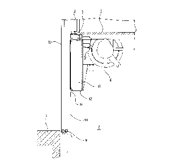
Fig. 2 shows a side view of a cage to be serviced,
Fig. 3 shows a front view of the lower cage part with a control box in operational setting,
10 Fig. 4 shows the control box in its first maintenance setting,
Fig. 5 shows a latching mechanism of the control box.
Fig. 1 shows a cage 1 with cage floor 2 and cage doors 2, which run in guide rails 4 in
15 front of the cage floor 2. The access to the cage 1 takes place by way of the storey floor 5
of the desired storey. Disposed below the cage floor 2 is a not-shown drive system with a
motor, which drives the drive wheels 6. These co-operate with guide columns 7, at which
the cage 1 is also guided above. The guide columns 7 can be free-standing or disposed in
a shaft 8.
In Figure 2 the cage 1 is shown in a maintenance position, in which the cage floor (2) is
disposed in front of a shaft door opening at about the eye level of a person. The lower
gùide rails 9 of the shaft doors 10 are shown at the front edge of the storey floor 5.
Disposed below the guide rails 4 for the cage doors 3 is the control box 11, which here
25 also receives components of the drive. It is laterally and downwardly received in a holder
12, which is mounted below the door threshold of the cage 1. The flatly constructed
control box 11 itself is basically closed towards five sides and covered at the front relative
to the shaft door opening in travel operation by an apron plate 13 mounted at the holder
12. The control box 11 thus forms the apron which is otherwise usual at lift cages and
30 which covers the shaft door opening in the case of inexact stopping of the cage at a
storey.
In order to open the control box 11 the apron plate 13 is pulled down as shown in Figure 2.
In this main~enance setting it covers the shaft door opening in its lower region. In order to

CA 02234333 1998-04-08
release the apron plate 13, initially fastening screws, which are not shown, are released
and then retaining springs (see also Figure 3) mounted at the apron plate 13 areunnotched by introducing a tool into holes 15. In the lowered end setting the retaining
springs notch in again. All electrical components of the control box 11 are now
conveniently ~essi~le for the engineer.
Figure 3 shows the control box 11 from the viewpoint of the engineer, wherein the
retaining spring 14 and hole 15 on the left side are marked in dashed lines. The retaining
spring 14 engages by its bent-around end in a slot-shaped opening of a detent tongue 16
10 mounted at the top at the control box 11. Lower detent tongues 17 receive the retaining
springs 14 in the mai"lenance setting of the apron plate 13. Travel and drive regulation
19, frequency inverter 20, ventilator 21, circuitbreaker 22, mains power supply unit 23, plug
24 and other electrical components are fastened on a carrier plate 18. Two handles 26
are disposed at the top at the control box 11. The flat mode of construction, which is
15 aligned by the wide side in the direction of the shaft door opening, of the control box 11
allows optimum access to the components. However, if due to space conditions a
p,~fer~bly square mode of construction should be required, the components can, for
exd" F'e, also be a"anged in multiple layering at pivotable-out or removable component
carriers.
In Figure 4 the control box 11 is disposed in its first maintenance setting. The cage floor 2
is for that purpose either open in its front region or tipped up in its entirety towards the rear
wall of the cage. Securing screws, which fix the carrier plate 18 in its operational setting at
the holder 12, are released. The holder 12 has on its rear side an oblique abutment
25 surface 27, along which the carrier plate 18 can be pulled up at the handles 26. Further,
the holder 12 has an obliquely arranged guide 28, in which guide blocks 29 at the carrier
plate 18 engage. The front side of the control box 11 is open, as the apron plate 13
remains at the holder 12. In this first ",ain~enance setting the components of the control
box 11 are isccessi'~le from the cage interior for measurements and simple operations. If a
30 fuller access should be required, for example for exchange of components, then the carrier
plate can also be pulled entirely out of the holder 12 after release of a securing means and
be laid by its closed rear side on the cage floor 2 or suit~le supports. In this second
maintenance setting sufficient standing area for the engineer still remains in the rearward
region of the cage 1; when the cage floor 2 is tipped up, he stands on the step plates 34.

CA 02234333 1998-04-08
Figure 5 shows the locking mechanism of the carrier plate 18 for the first maintenance
setting. Two retractable locking bars 30 project laterally in their lower locking setting and
are detentable at catches 31 in the region of the abutment surface 27 of the holder 12
(see also Figure 2). On dl~J~;n9 up the carrier plate 18 the spring-loaded catches
5 aulomalica"y fall back under pressure of the locking bars 30. For lowering of the carrier
plate 18 the locking bars 30 must be unlocked. This takes place through pulling of an
unlatching handle 32, which is conne~;led with the ends of the locking bars 30 by way of a
pull rod 24 (see upper setting). If the carrier plate 18 shall thus be guided from its first
main~enance setting back into the operalional setting again then the centre unlatching
10 handle 32 is held and the carrier plate 18 at this is lowered, tipped forward and secured by
screws in its operational seKing.
The control box 11 or the components 19, 20, etc., mounted on its carrier plate 18 remain
electrically connected by means of at least one cable 33 with the motor and other electrical
15 devices which are not shown, such as door drive, call transmitters, display devices, etc., in
every setting. This enables complete checkability of all lift functions even in maintenance
operation.
In departure from the illustrated exa",,c'e of embodiment the control box can also be
20 arranged above the cage doors. In that case the cage is, for maintenance, stopped
halfway below a storey floor, so that the control box in its turn is disposed at working
height of the engineer standing on the storey floor. In case of emergency this control box
is also accessible from the interior of the cage, in that the roof is at least partly removed
and the control box is let down into the cage.

Representative Drawing
A single figure which represents the drawing illustrating the invention.
Administrative Status

2024-08-01:As part of the Next Generation Patents (NGP) transition, the Canadian Patents Database (CPD) now contains a more detailed Event History, which replicates the Event Log of our new back-office solution.

Please note that "Inactive:" events refers to events no longer in use in our new back-office solution.

For a clearer understanding of the status of the application/patent presented on this page, the site Disclaimer , as well as the definitions for Patent , Event History , Maintenance Fee  and Payment History  should be consulted.

Event History

Description Date
Inactive: IPC from MCD 2006-03-12
Time Limit for Reversal Expired 2004-04-08
Application Not Reinstated by Deadline 2004-04-08
Deemed Abandoned - Failure to Respond to Maintenance Fee Notice 2003-04-08
Inactive: Abandon-RFE+Late fee unpaid-Correspondence sent 2003-04-08
Application Published (Open to Public Inspection) 1998-10-11
Inactive: First IPC assigned 1998-08-06
Inactive: IPC assigned 1998-08-06
Classification Modified 1998-08-06
Inactive: Filing certificate - No RFE (English) 1998-06-17
Application Received - Regular National 1998-06-16

Abandonment History

Abandonment Date Reason Reinstatement Date
2003-04-08

Maintenance Fee

The last payment was received on 2002-03-27

Note : If the full payment has not been received on or before the date indicated, a further fee may be required which may be one of the following

  • the reinstatement fee;
  • the late payment fee; or
  • additional fee to reverse deemed expiry.

Patent fees are adjusted on the 1st of January every year. The amounts above are the current amounts if received by December 31 of the current year.
Please refer to the CIPO Patent Fees web page to see all current fee amounts.

Fee History

Fee Type Anniversary Year Due Date Paid Date
Registration of a document 1998-04-08
Application fee - standard 1998-04-08
MF (application, 2nd anniv.) - standard 02 2000-04-10 2000-03-27
MF (application, 3rd anniv.) - standard 03 2001-04-09 2001-03-22
MF (application, 4th anniv.) - standard 04 2002-04-08 2002-03-27
Owners on Record

Note: Records showing the ownership history in alphabetical order.

Current Owners on Record
INVENTIO AG
Past Owners on Record
CHRISTOPH LIEBETRAU
KASPAR SCHINDLER
UTZ RICHTER
Past Owners that do not appear in the "Owners on Record" listing will appear in other documentation within the application.
Documents

To view selected files, please enter reCAPTCHA code :


To view images, click a link in the Document Description column (Temporarily unavailable). To download the documents, select one or more checkboxes in the first column and then click the "Download Selected in PDF format (Zip Archive)" or the "Download Selected as Single PDF" button.

List of published and non-published patent-specific documents on the CPD .

If you have any difficulty accessing content, you can call the Client Service Centre at 1-866-997-1936 or send them an e-mail at CIPO Client Service Centre.

({010=All Documents, 020=As Filed, 030=As Open to Public Inspection, 040=At Issuance, 050=Examination, 060=Incoming Correspondence, 070=Miscellaneous, 080=Outgoing Correspondence, 090=Payment})


Document
Description 
Date
(yyyy-mm-dd) 
Number of pages   Size of Image (KB) 
Representative drawing 1998-10-14 1 7
Description 1998-04-07 4 181
Abstract 1998-04-07 1 11
Claims 1998-04-07 1 36
Drawings 1998-04-07 4 68
Courtesy - Certificate of registration (related document(s)) 1998-06-16 1 116
Filing Certificate (English) 1998-06-16 1 163
Reminder of maintenance fee due 1999-12-08 1 111
Reminder - Request for Examination 2002-12-09 1 113
Courtesy - Abandonment Letter (Maintenance Fee) 2003-05-05 1 176
Courtesy - Abandonment Letter (Request for Examination) 2003-06-16 1 165