Note: Descriptions are shown in the official language in which they were submitted.
.- CA 02234868 2000-OS-O1
16978
GLASS GOB SHEARING APPARATUS 'VITH
IVIfIZOVf~D CUSI-fIONING OF SHEAR BLADE CARRIAGES
CROSS-REFERENCE TO RELATED PATENT
This application is directed to improvements in glass gob shearing apparatus
of the type described in U.S. Patent ~,~73,570 (Leidy et a1.1 .
FIELD OF THE INVENTION
This invention relates to apparatus for sequentially shearing each of a
multiplicity of streams of molten glass into individual gobs. More
particularly, this
invention relates to apparatus of the foregoing character in which opposed
sets of
shearing knife elements are simultaneously moved toward and away from one
another
along opposed, rectilinear paths to overlap in shearing relationship
approximately at
the longitudinal central axes of the streams of molten glass that are being
sheared.
BACKGROUND O:F THE INVENTION
In the manufacture of glass containers by a forming machine of the I.S.
("individual section") type, one or more streams of molten glass flow
downwardly
from a feeder bowl of a glass melting furnace forehea.rth toward a section of
the
molding machine, a~ad each stream is severed or sheared into a multiplicity of
individual gobs by a. shearing device positioned between the feeder bowl and
the
2o molding machine section. A typical shearing device of the foregoing
character
includes an opposed. set of shear knife elements, each set of shear knife
elements
being mounted on a carriage assembly, and driving apparatus for reciprocating
each of
the carriage assemblies toward and away from one another. A shearing device of
this
general character is disclosed in U.S. Patent No. 4,813,994 (Kulig).
Heretofore, such
25 driving apparatus typically utilized a mechanical cam arrangement in the
driving of
the carriage assemblies. Such a cam arrangement inherently is limited in the
speed
that can be imparted to the carriage assemblies, and this speed limitation can
act as a
capacity limitation on the, forming machine. Further, in such a cam
arrangement the
contact time between the shear knife elements and the glass stream(s), which
is an
30 important factor in the quality of the shearing action, cannot be adjusted
without
suspending the operation of the forming machine to permit a change in the
cams.
The foregoing and other problems and limitations of shearing devices for use
CA 02234868 1998-04-15
16978
with I.S. glass container forming machines were overcome with the shearing
apparatus of the invention of the aforesaid U.S. Patent 5,573,570, which uses
a
unidirectionally acting servo motor connected to an arm or throw of a bell
crank to
drive the opposed shear knife carriage assemblies of the shearing apparatus
through
separate connecting rods. Such a drive arrangement imparts harmonic movement
characteristics to the shear knife carriages. Further, with such a drive
arrangement
control of the operating speed of the servo motor, and control of the degree
of overlap
of the knife elements in their shearing portions, can be made during the
operation of
the shear device. As a result of these control characteristics, close control
of the "time
to under glass" of the shear device, that is, the contact time between the
molten glass
streams) and the shear knife elements, is provided. Further still, control of
the speed
of the servo motor can be very conveniently integrated with control of the
positions of
the needles that are used in conjunction with the feeder orifices to control
the rate of
glass flow from the feeder orifices.
Shearing apparatus of the type disclosed in the aforesaid U.S. Patent
5,573,570
must be capable of coming to a complete stop and the servo motor that drives
the
oscillating shear blade carriages of such apparatus must then be moved to a
fully
retracted position together with the shear blade carriages which are then also
retracted.
The servo motor apparatus of the aforesaid U.S. Patent 5,573,570, which is
urged to
its normal operating position by a pneumatic cylinder, is urged from its
normal
operating position by a tension spring that acts against the force from the
pneumatic
cylinder. It has been found, however, that stopping of such shearing apparatus
can be
very sudden, resulting in high impact loads on the elements of the pneumatic
cylinder
and other elements of the shearing apparatus due to the inertia of the shear
carriages as
they are being retracted from their operating positions.
Further, the piston end of the servo motor retracting pneumatic piston of the
shear apparatus of the aforesaid U.S. Patent 5,573,570 was fixed in relation
to the
support structure of such apparatus. It has been found, however, for precise
adjustment of the operating positions of the shear blades of the apparatus,
that it is
3o important that the piston end of such pneumatic piston be adjustable in
position
relative to such support structure.
CA 02234868 2000-OS-O1
mos
SU~I~IARY OF THE INVENTIOi~1
Accordinj to the present invention there is provided a parallel shear
apparatus
Generally in accordance with that disclosed in the aforesaid U.S. Patent
5,573,570 but
with a pneumatic cylinder for retracting the shear carriage from its normal
operating
position that is cushioned to reduce impact or shock loads on the cylinder and
the
structure to which it is mounted due to a sudden retraction of the servo motor
as a
result of a stoppage of the apparatus. Further, the piston end of the servo
motor
retraction pneumatic: cylinder of the parallel shear apparatus of the present
invention
is adjustable in its position relative to other structure of the shear
apparatus for more
precise positioning of the operating positions of the opposed set of shear
blades
relative to one another.
Accordingly, it is an object of the present invention to provide an improved
parallel shear device for a glass forming machine of the individual section
type. More
particularly, it is an object of the present invention to provide for improved
retraction
t5 of the elements of a shear device of the foregoing character in the event
of a stoppage
of production. It is, also an object of the present invention to provide a
parallel shear
device of the foregoing character in which the overlap of the shearing knife
elements,
in their shearing positions, can be conveniently and more precisely adjusted
without
suspending operation of the forming machine that is associated with such shear
device.
For a further understanding of the present invention and the objects thereof,
attention is directed to the drawing and the brief description thereof, to the
detailed
description of the preferred embodiment of the invention, and to the appended
claims.
IN THE DRAWIN~~
Fig. 1 is a plan view of a parallel shear apparatus for a glass forming
machine,
the parallel shear apparatus depicted therein incorporating the invention of
the
aforesaid U.S. Patent 5,573.,570;
Fig. 2 is an elevational view of the apparatus of Fig. 1 taken on line 2-2
thereof;
Fig. 3 is a schematic view of the pneumatic circuitry for actuating the
pneumatic operators of the apparatus of Figs. 1 and 2;
CA 02234868 1998-04-15
16978
Fig. 4 is a schematic view of the control system for controlling the operation
of the electrical motor of Figs. 1 and 2;
Figs. 5, 6 and 7 are fragmentary plan views of a modified embodiment of a
parallel shear apparatus for a glass forming machine according to the present
invention in different operating positions of such apparatus; and
Fig. 8 is a fragmentary perspective view of the apparatus of Figs. 5, 6 and 7.
DETAILED DESCRIPTION OF THE PREFERRED EMBODIMENT
A parallel shear apparatus or device according to the embodiment of the
present invention illustrated in Figs. 1-4 is indicated generally by reference
numeral
10 in Fig. 1 and includes opposed shear knife carriages 12 and 14. The
carriages 12
and 14 are mounted for reciprocating motion toward and away from one another,
the
carriage 12 being slidable along stationary slide rods 16 and 18 and the
carriage 14
being slidable along stationary slide rods 18 and 20.
The motion of the carriages 12 and 14 is rectilinear, and is simultaneously
actuated by an oscillating bell crank 22. In that regard, the carriage 12 is
connected to
a throw 24 of the bell crank 22 by a connecting rod 26, an end 26a of which is
pivotally attached to the carriage 12 and the other end 26b of which is
pivotally
attached to the throw 24 of the bell crank 22. Likewise, the carriage 14 is
connected
to a throw 28 of the bell crank 22 by a connecting rod 30, an end 30a of which
is
2o pivotally attached to the carriage 14 and the other end 30b of which is
pivotally
attached to the throw 28, the throws 24 and 28 being diametrically opposed to
one
another in their positions in relation to the bell crank 22.
The carriage 12 carries one or more shear knife elements, shown as four shear
knife elements 32a, 32b, 32c and 32d, one for each of the molten glass streams
flowing from the glass feeder thereabove (not shown) with which the shear
mechanism 10 is associated. Similarly, the carriage 14 carries a like number
of shear
knife elements, shown as shear knife elements 34a, 34b, 34c and 34d. As the
bell
crank 22 is caused to oscillate, by means which will hereinafter be described
more
fully, the carriages 12 and 14 are caused to move toward and then away from
one
3o another, to periodically bring the opposed shear knife elements, 32a and
34a, 32b and
34b, 32c and 34c, and 32d and 34d, respectively, into partly overlapping
relationship
with one another to thereby shear streams of molten glass flowing downwardly
CA 02234868 1998-04-15
16978
therebetween, at the locations identified by the broken line circles A, B, C
and D,
respectively. This action of the carriages 12, 14, and the shear knife
elements carried
by each of them, will separate the molten glass streams at the locations A, B,
C and D,
respectively, into individual glass gobs for further processing into
individual glass
containers by a glass forming machine of the individual section type, not
shown,
which is positioned below the shear mechanism 10.
The motion imparted to the carriages 12, 14 by the bell crank 22 through the
connecting rods 26, 30 will be harmonic in its velocity and acceleration
characteristics. This will minimize inertial loads on the carriages 12, 14 and
thereby
I o minimize wear on them.
The bell crank 22 is caused to oscillate about its central axis E by a
unidirectionally acting a.c. servo motor 36, gear reducer 38 combination,
which is
mounted on a bracket 40 that is pivoted in relation to the fixed structure of
the shear
mechanism 10 about a central axis F. The bracket 40 is biased against an
adjustable
15 stop 42 by a double acting pneumatic cylinder 44, and the position of the
bracket 40,
which is fixed in relation to the position of the central axis E of the bell
crank 22,
determines the amount or degree of overlap of the knife elements 32a and 34a,
etc., at
the innermost limits of their rectilinear motion. Thus, the degree overlap of
the knife
elements in their shearing position may be rapidly and easily made while the
shear
2o mechanism 10 is operating, without the need to interrupt the operation of
the
associated forming machine. The rotational movement of the servo motor 36 is
transmitted to the bell crank 22 by a connecting rod 46, an end 46a of which
is
pivotally attached to the servo motor 36 at a location away from the axis of
rotation of
the servo motor 36, and the other end 46b of which is pivotally attached to a
throw 48
25 of the bell crank 22 at a location between, and spaced from each of, the
throws 24 and
28.
Failsafe operation of the shear mechanism 10 is ensured by providing a tension
spring 50, which acts on the bracket 40 to retract the bracket 40 about its
pivot axis F
from its location against the adjustable stop 42 in the event of a loss of air
pressure in
3o the cylinder 44. Thus, the spacing between the carriages 12 and 14 will be
increased
to the point where there will be no overlap between their opposed knife
elements, 32a
and 34a, etc., even at the innermost limits of their travel, until proper
operating
CA 02234868 1998-04-15
16978
conditions can be restored. A pneumatic safety latch mechanism 52 is also
provided
to latch the bell crank 22 against oscillating motion in the event of the loss
of air
pressure to the cylinder 44 or the loss of power to or failure of the servo
motor 36.
The pneumatic circuitry for the operation of the cylinder 44 and the pneumatic
latch mechanism 52 is illustrated in Fig. 3, and utilizes a supply of clean,
regulated
pressurized air in a supply line 60. Air in the supply line 60 enters a
control cabinet
62, within a structure whose limits are indicated by a broken line, and the
control
cabinet 62 incorporates a pressure switch 64. The pressure switch 64 acts to
break the
flow of air through the supply line 60 in the event that the flow of air
through the
t o supply line falls below a predetermined value. The compressed air in the
supply line
60 is delivered, at locations downstream of the pressure switch 64, to a first
branch
line 66 and a second branch line 68.
The pressurized air in the branch line 66 is delivered to one or another of
the
operating sides of a piston 44a of the double acting cylinder 44 through a
solenoid
valve 70 from a supply manifold 72 in the control cabinet 62 and a second
supply
manifold 74 which is external to the control cabinet 62. The solenoid valve 70
is a
two-position valve of a conventional type, and its operating position is
electrically or
electronically controlled, for example, by wiring it into the emergency
shutoff
circuitry, not shown, for the shear device 10, to move the solenoid valve to
its non-
operating position and thereby cause the piston 44a of the cylinder 44 to move
to
advance the bracket 44 against the adjustable stop 42.
The pressurized air in the branch line 68 is delivered to the only operating
side
of a piston 52a of the single acting safety latch 52 through a solenoid valve
76, the
supply manifold 72 and the second supply manifold 74. The solenoid valve 76,
like
the solenoid valve 70, is a two-position valve of a conventional type, and its
operating
position is similarly electrically or electronically controlled to move the
solenoid
valve to a non-operating position in the event of an emergency and thereby to
permit a
spring 52b of the pneumatic safety latch 52 to bias the piston 52a from its
non-
engaged position, as depicted in Fig. 3, to its engaged position, in which it
will block
3o the oscillation of the bell crank 22.
Control of the operation of the apparatus of Figs. 1-3, as heretofore
described,
can be accomplished by means of the control system that is illustrated in Fig.
4. As
CA 02234868 1998-04-15
16978
shown, the operation of the a.c. servo motor 36 is controlled by a motion
controller 80
which acts on the servo motor 36 through a power amplifier 82. The motion
controller 80, which acts under the command of a supervisory computer 84, has
in its
memory a motion profile which is generated by the supervisory computer 84, and
this
memory profile determines the position of the knife elements 32a, 34a, etc.,
in relation
to the needles of the feeder bowl (not shown). In achieving this control
result, the
motion controller utilizes a signal indicative of the positions of the
needles, as
received from a resolver or feedback device 86, such as the resolver which is
described in U.S.P. 4,427,431 (Mumford) and a signal indicative of the
position of a
I o rotor of the servo motor 36, as received from a second resolver or
feedback device 88
of a similar nature. In that regard the resolver 86 is preferably mounted in
the same
place where the shear cam for prior art mechanical shears would be located,
and in
such an arrangement provides a signal indicative of the absolute position of
the output
shaft of the gearbox that is used to control the movement of the needles.
Likewise,
the resolver 88 is preferably mounted on the back of the servo motor 36, and
in such
an arrangement will serve to provide a signal indicative both of the position
of the
rotor of the servo motor 36 and of the positions of the carriages 12, 14.
In a control system as described, the supervisory computer 84 will calculate a
motion profile for the motion controller 80 based on the speed of the
associated
2o forming machine and the desired "time under glass" for the knife elements
32a, 34a,
etc., of the parallel shear apparatus 10. Thus, this motion profile will
control the
position to position relationship between the output shaft of the feeder
needle gearbox
and the desired positions of the knife elements 32a, 34a, etc. This
relationship can be
readily changed, when desired, by an operator through an operator interface
90, which
permits rapid reprogramming of the supervisory computer 84.
A parallel shear apparatus or device according to a modified embodiment of
the invention of Figs. 1-4 is illustrated in Figs. 5-8, wherein elements that
correspond
to the elements of the embodiment of Figs. I-4 are identified by a 100 series
numeral,
the last two digits of which correspond to the two digits of the corresponding
elements
of the embodiments of Figs. 1-4.
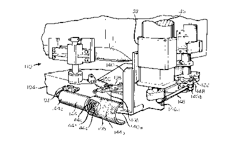
The embodiment of a parallel shear apparatus or device according to the
embodiment of the present invention illustrated in Figs. 5-8 is indicated
generally by
CA 02234868 1998-04-15
16978
reference numeral 110, and corresponds to the parallel shear apparatus 10 of
Figs. 1-4,
except as hereinafter described. The parallel shear apparatus 110 is shown in
its
relationship to a feeder bowl BL of an associated forehearth, shown in broken
line in
Figure S only, and has an opposed pair of shear knife carriages, not shown,
which are
caused to advance toward and away from one another by an oscillating bell
crank 122.
Reciprocating motion is imparted to the shear knife carriages by connecting
rods 126
and 130, an end 130b of the connecting rod 130 being pivotably attached to a
throw
128 of the bell crank 122 and an end 126b of the connecting rod 126 being
pivotably
attached to a throw 124 of the bell crank 122. In that regard, the throws 124
and 128
of the bell crank 122 are diametrically opposed to one another in their
positions in
relation to the bell crank 122, and the motion imparted to the opposed shear
knife
carriages by the bell crank 122 through the connecting rods 126, 130 will be
harmonic
in its velocity and acceleration characteristics, to minimize inertia loads on
the shear
knife carriages and thereby minimize wear on them.
The bell crank 122 is caused to oscillate about its central axis E by a
unidirectionally acting a.c. servo motor 136, gear reducer 138 combination,
which is
mounted on a bracket 140 that is pivoted in relation to the fixed structure of
the shear
mechanism 110 about a central axis F. The bracket 140 is biased against an
adjustable
stop 142 by a double acting pneumatic cylinder 144. Rotary motion of the servo
2o motor 136 is converted to oscillating motion of the bell crank 122 by
connecting the
servo motor 136 to a throw 148 of the bell crank 122 by a connecting rod 146,
an end
146a of the connecting rod 146 being pivotably attached to the servo motor 136
at a
location away from the axis of rotation of the servo motor 136, and an end
146b of the
connecting rod 146 being pivotably attached to the throw 148 of the bell crank
122 at
a location between, and spaced from each of, the throws 124 and 128.
Failsafe operation of the shear mechanism 110 is ensured in the event of a
stoppage, or otherwise, by providing a tension spring 150. An end 1 SOa of the
spring
150 is secured to a bracket 192 that is fixedly mounted to a frame 194 with
respect to
which the carriages that are reciprocated by the oscillating motion of the
bell crank
122. Another end 1 SOb of the spring 150 is secured to a pivotable link 196,
and
pivoting motion of the link 196 is transmitted to the pivoting bracket 140 by
a second
pivotable link 198, an end 198a of which is pivotably secured to the bracket
140 and
CA 02234868 2000-OS-O1
169~s
another end 198b oFwhich is slidable in a slot 196a of the link 196. The
cylinder 144
has a piston end 144a that is pivotably mounted to a mounting bracket 193, and
the
cylinder 144 further has a rod end 144b that is pivotably secured to the end
198b of
the link 198. Thus, expansion of the cylinder 144 is effective to pivot the
bracket 140
against the stop 1=1:?, as sho~.vn in Figs. ~ and 6, wlich is the normal
condition of the
bracket 140 when the shear device 110 is in operation. In that regard, Fig. ~
shows
the condition of the; shear device 1 I O when the carriages are actuated by
the
connecting rods 126 and 130 are at the innermost limits of their normal
reciprocating
motions, and Fig. E. indicates the condition of the shear device 1 I O when
the shear
t p carriages which are; actuated by the connecting rods 126 and 130 are at
the outermost
limits of their normal paths of reciprocation.
When it is desired to stop the operation of the shear device I 10, either
manually or automatically, the pneumatic pressure to the cylinder 144 is
discontinued,
allowing the spring; 150 to pivotably retract the bracket I40 about its axis F
to the
t 5 condition illustrated in Fig. 7, at which time the space between the
carriages operated
by the connecting rods 126 and 130 will be substantially greater than the
spacing in
the condition illustrated in F ig. 6. Because of the inertia of the carriages
operated by
the connecting rods 126 and I30, a sudden stopping of the shear device I I0,
which
will cause it to assi.ime the condition illustrated in Fig. 7, can impose
rather substantial
2o shock loads on various elements of the shear device I 10. To absorb the
shock loads
that otherwise would result from a sudden stoppage of the shear device 1 I0, a
cylinder
rod portion 144c of the cylinder 144 is provided with a rod clevis 144b and an
annular
free end portion I~~4j of which is fixedly secured to a free end of the
cylinder rod
portion, the rod cle;vis 144b having an annular collar portion 144d formed as
an
25 integral element thereof. A, compression spring 144f circumscribes the rod
portion
144c between the collar portion 144d and an end 144g of a housing I44h. Thus,
as
the shear device I IO moves to its stopped, Fig. 7 condition, the collar I44d
engages,
and begins to compress, the spring 144f, to thereby absorb the shock loads
that would
otherwise be imposed on various elements of the shear device 110. A part
cylindrical
3o shield 195 is provided to shield the exposed end of the rod 144c and the
spring 144f
from external cone:act. The rod clevis 144b is also provided, as an integral
element
thereof, with a clevis portion: that pivotably engages an arm portion 140a of
the
CA 02234868 2000-OS-O1
16978
bracket 140 to retract the bracket 140 about the axis P from its position of
Figs. ~ and
6 to its Fig. 8 position. The use of a single piece rod clevis 144bhas been
found to
facilitate position adjustments of the parallel shear apparatus 110 and to
prevent
damage that could otherwise: occur due to improper adjustments.
To permit precise adjustments of the operating and stopped conditions of the
bracket 140, the bracket 19~~ to which the cylinder 144 is mounted is
adjustably
secured to the brac~;et 192.
A pneumatic safety latch mechanism 152 is also provided to latch the bell
crank 122 against oscillating motion in the event of the lose of air pressure
to the
!0 cylinder 144 or the loss of power to or failure of the servo motor 136.
Although th.e best mode contemplated by the inventors for carrying out the
present invention as of the filing date hereof has been shown and described
herein, it
will be apparent to those skilled in the art that suitable modifications,
variations and
equivalents may be made without departing from the scope of the invention,
such
~ 5 scope being limited solely by the terms of the following claims and the
legal
equivalents thereof.
What is claimed is: