Language selection

Search

Patent 2235011 Summary

Third-party information liability

Some of the information on this Web page has been provided by external sources. The Government of Canada is not responsible for the accuracy, reliability or currency of the information supplied by external sources. Users wishing to rely upon this information should consult directly with the source of the information. Content provided by external sources is not subject to official languages, privacy and accessibility requirements.

Claims and Abstract availability

Any discrepancies in the text and image of the Claims and Abstract are due to differing posting times. Text of the Claims and Abstract are posted:

  • At the time the application is open to public inspection;
  • At the time of issue of the patent (grant).
(12) Patent: (11) CA 2235011
(54) English Title: HYDROCYCLONE SEPARATOR
(54) French Title: SEPARATEUR HYDROCYCLONE
Status: Expired and beyond the Period of Reversal
Bibliographic Data
(51) International Patent Classification (IPC):
  • D21D 5/24 (2006.01)
  • B4C 3/00 (2006.01)
(72) Inventors :
  • LIVSEY, JAMES D. (United States of America)
(73) Owners :
  • VOITH SULZER PAPER TECHNOLOGY NORTH AMERICA, INC.
(71) Applicants :
  • VOITH SULZER PAPER TECHNOLOGY NORTH AMERICA, INC. (United States of America)
(74) Agent: SMART & BIGGAR LP
(74) Associate agent:
(45) Issued: 2003-10-14
(22) Filed Date: 1998-04-16
(41) Open to Public Inspection: 1998-12-04
Examination requested: 1998-04-16
Availability of licence: N/A
Dedicated to the Public: N/A
(25) Language of filing: English

Patent Cooperation Treaty (PCT): No

(30) Application Priority Data:
Application No. Country/Territory Date
08/868,628 (United States of America) 1997-06-04

Abstracts

English Abstract


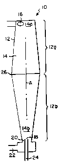
An apparatus for separating relatively light fractions from relatively dense fractions in a pulp
suspension. The apparatus has a tubular housing of circular cross section defining a separation
chamber extending longitudinally from an inlet end to an outlet end, with an inlet at the inlet end for
tangentially introducing a flow of the pulp suspension into the housing for vortical flow along the
length of the separation chamber towards the outlet. The vortical flow effects a separation of the
relatively light fraction from the relatively dense fraction. The housing has at least two outlets at the
outlet end, one outlet being positioned to accommodate an exiting flow of the relatively light fraction
and the other outlet being positioned to accommodate an exiting flow of the relatively dense fraction.
The diameter of the separation chamber at an intermediate region along its length is enlarged in
comparison to its diameter at the inlet and outlet ends.


French Abstract

Cette invention concerne un appareil pour la séparation de la fraction relativement légère et de la fraction relativement dense d'une pulpe. L'appareil comporte un corps tubulaire de section circulaire définissant une chambre de séparation, avec l'admission à une extrémité et l'évacuation à l'extrémité opposée, dans le sens longitudinal. L'extrémité d'admission présente un orifice d'admission pour admettre tangentiellement dans la chambre de séparation le courant de pulpe à séparer, de manière à créer un écoulement tourbillonnaire dans la chambre jusqu'à l'extrémité d'évacuation. Ce tourbillon opère la séparation des fractions relativement légère et relativement dense de la suspension. L'extrémité d'évacuation présente au moins deux orifices d'évacuation, disposés l'un pour permettre l'évacuation de la fraction relativement légère et l'autre, celle de la fraction relativement dense. Le diamètre de la section médiane de la chambre de séparation est supérieur à celui des sections extrêmes.

Claims

Note: Claims are shown in the official language in which they were submitted.


WE CLAIM:
1. Apparatus for separating a relatively light fraction of a pulp suspension
from a relatively
dense fraction of said pulp suspension, said apparatus comprising:
a tubular housing of circular cross section defining a separation chamber
extending
longitudinally from an inlet end to an outlet end, the diameter of said
separation chamber at an
intermediate region along the length thereof being enlarged in comparison to
the diameter of said
separation chamber at said inlet and outlet ends;
an inlet at said inlet end for tangentially introducing a flow of said pulp
suspension into
said housing for vortical flow along the length of said separation chamber
towards said outlet
end, said vortical flow effecting a separation of said relatively light
fraction from said relatively
dense fraction; and
accept and reject outlets for receiving the separated fractions of said pulp
suspension at
the outlet end of said separation chamber, said reject outlet being aligned
with the longitudinal
axis of said separation chamber to receive said relatively light fraction, and
said accept outlet
being disposed radially outwardly from said reject outlet to receive said
relatively dense fraction.
2. The apparatus as claimed in claim 1 wherein the diameter of said separation
chamber
increases gradually from said inlet end to said intermediate region, and
decreases gradually from
said intermediate region to said outlet end.
3. The apparatus as claimed in claim 2 wherein the changes in separation
chamber diameter
are linear.
4. The apparatus as claimed in claim 2 wherein the changes in separation
chamber diameter
are non-linear.
5. The apparatus as claimed in claim 1 wherein said housing is defined by two
hollow
truncated conical sections joined one to the other at said intermediate
region.
6. A hydrocyclone apparatus for separation of a light fraction of a pulp
suspension from a
denser fraction of said suspension, comprising:
a separation chamber;
-8-

an inlet means disposed at an inlet end of said separation chamber for
introducing said
pulp suspension into said separation chamber; and
at least two outlet means disposed at an opposite outlet end of said
separation chamber
for removal of the separated fractions of said pulp suspension;
the diameter of said separation chamber increasing gradually from said inlet
end to an
intermediate region and then decreasing gradually from said intermediate
region to said outlet
end.
-9-

Description

Note: Descriptions are shown in the official language in which they were submitted.


CA 02235011 1998-04-16
HYDROCYCLONESEPARATOR
BACKGROUND OF THE INVENTION
1. Field of the Invention
The present invention relates to an apparatus commonly referred to as a
"hydrocyclone" used to separate a light fraction from a liquid/solid
suspension.
2. Description of the Prior Art
Hydrocyclones are commonly used to separate contaminants from liquid/solid
suspensions, e.g. pulp/water suspensions. The suspension enters the
hydrocyclone through
an inlet disposed tangentially to the interior wall of a longitudinally
extending separation
chamber. The inlet pressure creates a high inlet velocity which in turn sets
up a free liquid
vortex within the chamber with a central air core. Centrifugal forces act on
the liquid and
solids resulting in a separation based on their relative densities. The size
and shape of the
solids, the geometry of the hydrocyclone, and the properties of the liquid
will also
significantly affect the efficiency of the separation. The hydrocyclone will
have at least two
outlets from the separation chamber, one outlet being positioned to
accommodate an outflow
of the less dense fraction and the other outlet being positioned to
accommodate the outflow
of the higher density fraction. Many hydrocyclones are designed to create a
separation,
from the suspension, of the denser fraction. Other hydrocyclones have been to
designed to
remove the less dense fraction from the suspension.
-2-

CA 02235011 2002-10-08
SUMMARY OF THE INVENTION
A general object of the present invention is to provide a hydrocyclone capable
of
improved performance as compared to conventional hydrocyclones of the type
currently in
use.
A more specific object of the present invention, when processing pulp/water
suspensions, is to achieve a reduction of useful papermaking fibers in the
flow from the
rej ect outlet.
A companion objective of the present invention is to achieve a higher
throughput
for a given pressure drop between the inlet and the accept outlet of the
hydrocyclone.
The hydrocyclone of the present invention is designed to separate contaminants
having a specific gravity of less than 1.00, from a papermaker's pulp/water
suspension.
Such contaminants typically include many plastics, waxes and adhesives that
enter the pulp
stream during the recycling of waste paper.
In one embodiment, the hydrocyclone has a tubular housing of circular cross
section
defining a separation chamber extending longitudinally from an inlet end to an
outlet end.
The diameter of the separation chamber at an intermediate region along the
length thereof
is enlarged in comparison to the diameter of the separation chamber at the
inlet and outlet
ends. The hydrocyclone also has an inlet at the inlet end for tangentially
introducing a flow
of the pulp suspension into the housing for vortical flow along the length of
the separation
chamber towards the outlet end. The vortical flow effects a separation of the
relatively light
fraction from the relatively dense fraction. The hydrocyclone also has accept
and reject
outlets for receiving the separated fractions of the pulp suspension at the
outlet end of the
-3-

CA 02235011 2002-10-08
separation chamber. The reject outlet is aligned with the longitudinal axis of
the separation
chamber to receive the relatively light fraction. The accept outlet is
disposed radially
outwardly from the reject outlet to receive the relatively dense fraction.
In a further embodiment, a hydrocyclone a separation chamber, an inlet means
disposed at an inlet end of the separation chamber for introducing the pulp
suspension into
the separation chamber and at least two outlet means disposed at an opposite
outlet end of
the separation chamber for removal of the separated fractions of the pulp
suspension. The
diameter of the separation chamber increases gradually from the inlet end to
an
intermediate region and then decreases gradually from the intermediate region
to the outlet
end.
For discussion purposes, the separation chamber may be subdivided into an
inlet
portion extending from the tangential inlet to an intermediate region along
the longitudinal
chamber axis, and an outlet portion beginning at the intermediate region and
extending to
the outlet end. The diameter of the inlet portion increases gradually from the
inlet to the
intermediate region, and the diameter of the outlet portion decreases
gradually from the
intermediate region to the outlet end.
In a preferred embodiment of the invention, the tubular housing is defined by
two
truncated conical sections joined together at their large diameter ends, with
the changes in
the diameter of the separation chamber being linear.
In other embodiments of the invention, the tubular housing is subdivided into
mating portions which vary the diameter of the separation chamber in a non-
linear
relationship.
-4-

CA 02235011 2002-10-08
These and other objects, features and advantages of the present invention will
become more apparent as the description proceeds with the aid of the
accompanying
drawings, wherein:
BRIEF DESCRIPTION OF THE DRAWINGS
Figure 1 is a diagrammatic longitudinal sectional view taken through one
embodiment of a hydrocyclone in accordance with the present invention; and
Figures 2 and 3 are similar views showing alternative embodiments of
-4A-

CA 02235011 1998-04-16
DETAILED DESCRIPTION OF THE ILLUSTRATED EMBODIMENTS
With reference initially to Figure 1, a hydrocyclone apparatus in accordance
with
a preferred embodiment of the present invention is generally depicted at 10.
The apparatus
includes a tubular housing 12 of circular cross section defining a separation
chamber 14.
The separation chamber extends longitudinally from an inlet end 14a to and
outlet end 14b.
An inlet 16 is disposed tangentially to and in communication with the inlet
end 14a of the
separation chamber. A reject outlet 18 and an accept outlet 20 are disposed
concentrically
at the outlet end 14b of the separating chamber. The accept outlet 20 leads to
an accept
nozzle 22 having an axis that may be disposed either parallel or perpendicular
to the
longitudinal axis A of the separation chamber 14. Likewise, the reject outlet
18 leads to a
reject nozzle 24 which may be similarly disposed with respect to the
longitudinal axis A.
The housing 12 has an inlet portion 12a leading from the inlet end 14a of the
separation chamber to an intermediate region 26, and an outlet portion 12b
leading from the
intermediate region to the outlet end 14b of the separation chamber. The
diameter of the
separation chamber 14 in the inlet portion 12a increases gradually from the
inlet end 14a to
the intermediate region 26. The diameter of the separation chamber in the
outlet portion
12b decreases gradually from the intermediate region 26 to the outlet end 14b.
The inlet and outlet housing portions 12a, 12b comprise truncated conical
sections,
with their larger diameter bases joined one to the other at the intermediate
region 26, and
with the changes in their internal diameters being linear.
The pulp suspension enters the entry end 14a of the separating chamber
tangentially
via inlet 16, thereby setting up a free vortex in the separation chamber. The
pulp
-5-

CA 02235011 1998-04-16
suspension moves in the longitudinal direction towards the outlet end 14b,
passing first
through the housing section 12a and then through the housing section 12b. The
heavier
fraction of the pulp suspension will exit the separation chamber 14 via the
accept outlet 20
and communicating nozzle 22. The lighter fraction of the pulp suspension will
exit the
separation chamber through the reject outlet 18 and communicating nozzle 24.
The above described housing and separation chamber configuration has been
shown
to provide improved results over conventional hydrocyclones having separation
chambers
with either cylindrical inlet portions or separation chambers with diameters
which constantly
decrease toward the outlet end.
Of particular significance is the ability of the present invention to achieve
a reduction
of useful papermaking fibers in the flow from the reject outlet. In addition,
a higher
throughput for a given pressure drop from the inlet to the accept outlet may
be achieved.
These advantages are indicative of a flow through the apparatus having a more
stable vortex
and a straighter core.
Figure 2 is a cross-sectional view similar to Figure 1 showing an alternative
embodiment of the invention wherein the inlet and outlet portions 112a, 112b
of the housing
112 are curved to provide gradual but non-linear changes in the diameter of
the separation
chamber 14.
Figure 3 illustrates another embodiment of the invention wherein the inlet and
outlet
portions 212a, 212b have different curvatures, again providing non-linear
variations for the
diameter of the separation chamber 14.
-6-

CA 02235011 1998-04-16
While the embodiments shown in Figures 1-3 have different configurations, they
each share a common characteristic, namely, that the diameter of the
separation chamber
at an intermediate region along its length is enlarged in comparison to the
diameter of the
separation chamber at the inlet and outlet ends.
It is my intention to cover these and any other modifications or variations
encompassed by the scope of the claims appended hereto.

Representative Drawing
A single figure which represents the drawing illustrating the invention.
Administrative Status

2024-08-01:As part of the Next Generation Patents (NGP) transition, the Canadian Patents Database (CPD) now contains a more detailed Event History, which replicates the Event Log of our new back-office solution.

Please note that "Inactive:" events refers to events no longer in use in our new back-office solution.

For a clearer understanding of the status of the application/patent presented on this page, the site Disclaimer , as well as the definitions for Patent , Event History , Maintenance Fee  and Payment History  should be consulted.

Event History

Description Date
Time Limit for Reversal Expired 2009-04-16
Letter Sent 2008-04-16
Inactive: IPC from MCD 2006-03-12
Grant by Issuance 2003-10-14
Inactive: Cover page published 2003-10-13
Inactive: Final fee received 2003-07-18
Pre-grant 2003-07-18
Notice of Allowance is Issued 2003-01-29
Letter Sent 2003-01-29
4 2003-01-29
Notice of Allowance is Issued 2003-01-29
Inactive: Approved for allowance (AFA) 2003-01-16
Amendment Received - Voluntary Amendment 2002-10-08
Inactive: S.30(2) Rules - Examiner requisition 2002-04-11
Application Published (Open to Public Inspection) 1998-12-04
Amendment Received - Voluntary Amendment 1998-08-27
Classification Modified 1998-08-14
Inactive: First IPC assigned 1998-08-14
Inactive: IPC assigned 1998-08-14
Inactive: Filing certificate - RFE (English) 1998-06-25
Inactive: Applicant deleted 1998-06-22
Application Received - Regular National 1998-06-22
Request for Examination Requirements Determined Compliant 1998-04-16
All Requirements for Examination Determined Compliant 1998-04-16

Abandonment History

There is no abandonment history.

Maintenance Fee

The last payment was received on 2003-03-27

Note : If the full payment has not been received on or before the date indicated, a further fee may be required which may be one of the following

  • the reinstatement fee;
  • the late payment fee; or
  • additional fee to reverse deemed expiry.

Patent fees are adjusted on the 1st of January every year. The amounts above are the current amounts if received by December 31 of the current year.
Please refer to the CIPO Patent Fees web page to see all current fee amounts.

Owners on Record

Note: Records showing the ownership history in alphabetical order.

Current Owners on Record
VOITH SULZER PAPER TECHNOLOGY NORTH AMERICA, INC.
Past Owners on Record
JAMES D. LIVSEY
Past Owners that do not appear in the "Owners on Record" listing will appear in other documentation within the application.
Documents

To view selected files, please enter reCAPTCHA code :


To view images, click a link in the Document Description column (Temporarily unavailable). To download the documents, select one or more checkboxes in the first column and then click the "Download Selected in PDF format (Zip Archive)" or the "Download Selected as Single PDF" button.

List of published and non-published patent-specific documents on the CPD .

If you have any difficulty accessing content, you can call the Client Service Centre at 1-866-997-1936 or send them an e-mail at CIPO Client Service Centre.


Document
Description 
Date
(yyyy-mm-dd) 
Number of pages   Size of Image (KB) 
Representative drawing 1998-12-09 1 3
Representative drawing 2003-10-09 1 3
Cover Page 2003-10-09 1 35
Abstract 1998-08-26 1 23
Drawings 1998-08-26 1 13
Description 2002-10-07 7 241
Claims 2002-10-07 2 71
Abstract 1998-04-15 1 22
Claims 1998-04-15 2 60
Drawings 1998-04-15 2 21
Description 1998-04-15 6 196
Cover Page 1998-12-09 2 58
Courtesy - Certificate of registration (related document(s)) 1998-06-24 1 117
Filing Certificate (English) 1998-06-24 1 163
Reminder of maintenance fee due 1999-12-19 1 111
Commissioner's Notice - Application Found Allowable 2003-01-28 1 160
Maintenance Fee Notice 2008-05-27 1 171
Correspondence 2003-07-17 1 41
Fees 2001-03-29 1 43
Fees 2007-04-10 1 35