Note: Descriptions are shown in the official language in which they were submitted.
CA 02235255 1998-04-17
- 1 -
W097/14562 (as amended)
Ink Knife for an Ink Duct Roller
of a Printing Machine
The invention relates to a process for production of an ink
knife for an ink duct roller of a printing machine from a
metal plate at least approximately 2 mm thick, where
parallel slots are formed which extend at right angles from
the working edge of the ink knife over part of the plate
width and form blades of ink zone width.
Multiple-blade ink knives are known for example from CH-A5
602345. This ink knife has in the area of the working edge
recesses which lie on both sides of adjustment screws next
to the blades. The blades can be adjusted individually, a
mechanical influence on the adjacent blade area is excluded
or at least substantially reduced. The thickness of the ink
layer can be set on each blade, individual ink amounts in
the different ink zones can be changed as required by the
printing image in the different ink zone widths. The
disadvantage of this solution is the intermediate spaces
between the blades which allow the passage of even high
viscosity inks and the formation of annular rings on the ink
ductor.
According to the known state of the art, various measures
are proposed which prevent at least in part the penetration
of ink into the slots but always entail other disadvantages.
According to DE, A1 2228625, the slots between the blades of
an ink knife are filled with a plastic. This mechanically
decouples adjacent blades thanks to the elasticity of the
plastic. As the usage period increases however there is an
increasing risk that parts of the plastic, in particular'
when a blade is greatly deflected in comparison with its
neighbour, will come loose and harm the print quality.
CA 02235255 1998-04-17
- 2 -
Numerous design forms are known according to which the slots
between the blades of an ink knife are covered either with a
metal or with a plastic foil, for example according to US,A
2837024. These cover foils are effective but cause
substantial problems for example as a result of wear and
penetration of the ink between the foil and the blades.
DE, A1 4323047 describes an ink knife which has a .complete
working edge , known as the active edge , to set the quantity
of ink. The formation of deep grooves which leave little
residual material and T-shaped slots allow a finely graded
sectorial adjustment without adjacent sectors changing their
distance from the ink roller. An essential part of the
doctrine of this objection consists of achieving a complete
acting edge.
In DE,C1 3525589, the working edge of an ink knife is
slotted with a wire erosion machine or with laser beams. An
adhesive coating of a material softer than the ink knife has
a greater thickness than the width of the slot. When the
blade is adjusted, the excess material is cut away and the
slot completely closed. The penetration of ink into the
narrow slot is prevented with complex measures.
According to EP, B1 0376885, ink knives are produced which
have slots formed by laser beams of a width of 0.1 to 0.3
mm, which prevents leakage without additional cover in the
case of high viscosity printing inks. In addition to the
defined slot widths, the ink knife must have the following
properties:
- The slots must be longer than half the plate width but
must not exceed two-thirds thereof.
- The thickness of the plate must be at least twice the
maximum adjustment path of the blades.
CA 02235255 2001-09-24
_ 3 _
Preferred plate thicknesses are 1 to 3 mm. It has been
shown that in the thicker plate range extremely narrow slots
from 0.01 to 0.03 mm width can only be cut out cleanly and
regularly with great difficulty, if at all. Furthermore
this solution is limited to high viscosity inks.
EP, A1 0594536 describes a knife formed as a flexible steel
plate for the ink duct of an offset printing machine which
has blades in the area of the working edge. These are can
be bent differently in zones in relation to an ink ductor
thanks to individually adjustable setting elements.
According to a special design form, the knife has at least
on one side a weakening groove running parallel to the
working edge, preferably along the ends of the blades, which
increases the flexibility of the blades.
DE,A1 3100383 describes protection for the ink ducts of
printing machines which prevents ink contamination of the
adjustment and support elements. The flexible metal or
plastic protective plate is to this end firmly attached to
the underside of the ink knife.
The present invention is based on the task of creating a
process of the type described initially which considerably
facilitates and rationalises the production of narrow slots
in particular with laser beams. In particular with a metal
plate thickness of at least 2 mm, an extremely narrow
regular cut can be made with laser beams and the blades
formed, despite their thickness, can be adjusted with
appropriate use of force. Furthermore there is the option
of preventing or at least reducing by additional means the
harmful consequences of ink of a lower viscosity range
penetrating the slot.
CA 02235255 2001-09-24
-3a-
The task is solved according to the present invention by:
(a) first, cutting blind-ended, parallel transverse
grooves out of the metal plate at intervals corresponding
to the ink zone width starting from the working edge, and
(b) then, cutting through the metal plate in the area of
the transverse grooves, including the working edge, to
form said narrow slots at intervals corresponding to the
ink zone width.
CA 02235255 1998-04-17
- 4 -
special and further design forms of the process are the
subject of dependent patent claims.
The process according to the invention creates the
possibility, even when thick metal plates are used, of
constructing ink knives with extremely narrow slots without
the occurrence of technical problems which are difficult to
solve. The thickness of the metal to be cut preferably by
the laser beam is always less than the thickness of the
metal plate. This residual thickness is limited by the
deflection of the blades on adjustment to an ink duct
roller. As this adjustment path in practice is relatively
small, the transverse grooves can be formed correspondingly
deep and hence facilitate the slot formation by the
preferred laser process.
Even with very great plate thicknesses, the mobility of the
blades is always guaranteed to the required extent as
suitably at the blind slot end on at least one side of the
metal plate a weakening groove of selectable depth is
provided.
It is a feature of essential importance that (b) is always
carried out after (a), otherwise the benefits of laser
cutting through a thinner metal layer cannot be exploited
and this would no longer correspond to the present
invention.
The transverse grooves are preferably cut out at a width of
50 to 200 of the plate thickness at a depth of 20 to 80% of
this plate thickness. For production of an ink knife,
suitably a metal plate of spring steel is used which is 2 to
5 mm, in particular 3 mm thick. The depth of the transverse
grooves in this case is preferably in the range from 1 mm to
d - 1 mm, where d indicates the thickness of the metal
plate.
CA 02235255 1998-04-17
- 5 -
The cross sectional form of the transverse grooves is not
significant in itself; in addition to rectangular, square,
trapezoid, semi-circular or circle segment shape, it can
assume any other form suitable for production. Usually
transverse grooves of rectangular section are milled out of
a metal plate before or after the plate is hardened.
Suitably in a subsequent working process the weakening
groove is milled out of the metal plate on the same side.
The longitudinal weakening grooves can however also be cut
out on both sides of the plate. When formed on one and both
sides, a semi-circular or circle-segment shaped cross
section form is particularly suitable for a weakening
groove. As indicated however the weakening groove can also
be rectangular, square or even formed as a simple broad cut
corresponding to the cross section form of the transverse
grooves. Depending on the adjustment force available for
the blades on the ink duct roller, the weakening groove or
grooves are recessed more or less deeply.
The slots usually produced with the laser beams between the
blades suitably have a width of maximum approx 0.05 mm, in
particular 0.01 to 0.02 mm. The narrower the slot, the less
ink can penetrate if this is not of high viscosity. In
particular in the upper range of slot widths, instead of the
laser beams an equivalent process can be used for example
wire erosion.
According to a further design form of the invention, the
transverse grooves are filled with an elastic mass which
does not penetrate the grooves. This ensures a perfect seal
of the slots. This mass in no case metallic, 'preferably
consists of a plastic, an acid resistant silicon mass or an
inserted rubber profile, for example a rubber cord.
Evidently, if required, the weakening groove can also be
filled with the elastic mass. -
CA 02235255 2001-09-24
-6-
According to a preferred design form of the invention,
the transverse grooves in the metal plate are covered at
least in the area of the working edge with a first leg of
an angled scraper. Its second freely projecting leg is
bent or folded through an angle of preferably 30 to 60°.
The angled scraper consists for example of a 0.05 to
0.1 mm thick metal plate or a plastic profile.
The first leg of the angled scraper is preferably glued
to the blades of the metal plate. Thanks to the
transverse grooves, the individual blades for adjustment
have the necessary freedom of movement without mechanical
effect on adjacent blades.
Therefore, in accordance with the present invention,
there is provided a process for production of an ink
knife for an ink duct roller of a printing machine from a
metal plate at least approximatley 2 mm thick, where
parallel slots are formed which extend from the working
edge of the ink knife over a part of the plate width and
form blades of ink zone width, characterised in that for
simplified production of extremely narrow regular slots
of a width of maximum approximately 0.05 mm
(a) first, blind-ended, parallel transverse grooves
are cut out of the metal plate at intervals corresponding
to the ink zone width starting from the working edge, and
(b) then, the metal plate is cut through in the
area of the transverse grooves, including the working
edge, to form a narrow slot at intervals corresponding to
the ink zone width.
CA 02235255 2001-09-24
-6a-
Also in accordance with the present invention, there is
provided a process which comprises: producing an ink
knife for an ink duct roller of a printing machine from a
metal plate at least approximately 2 mm thick; forming
narrow parallel slots which extend from a working edge of
the ink knife over a part of the plate width, and forming
blades of ink zone width, including the steps of
(a) first, cutting blind-ended, parallel transverse
grooves out of the metal plate at intervals corresponding
to the ink zone width starting from the working edge, and
(b)then, cutting through the metal plate in the area
of the transverse grooves, including the working edge, to
form said narrow slots at intervals corresponding to the
ink zone width.
Further in accordance with the present invention, there
is provided a process which comprises: producing an ink
knife for an ink duct roller of a printing machine from a
metal plate at least approximately 2 mm thick; forming
narrow parallel slots which extend from a working edge of
the ink knife over a part of the plate width, and forming
blades of ink zone width, including the steps of
(a) first, cutting blind-ended, parallel transverse
grooves out of the metal plate at intervals corresponding
to the ink zone width starting from the working edge, and
(b) then, cutting through the metal plate in the
area of the transverse grooves, including the working
edge, to form said narrow slots at intervals
corresponding to the ink zone width,
and wherein the slots are produced with laser beams
and a complete weakening groove is cut in the area of
CA 02235255 2001-09-24
-6b-
blind ends of the transverse grooves running parallel to
the working edge.
The invention is described in more detail using the
design examples shown in the drawing which are also the
subject of dependent patent claims. The diagrams show:
- Fig 1 a partial top view of an ink knife,
- Fig 2 a front view of Fig 1,
- Fig 3 a side view of Fig 1,
- Fig 4 an enlarged partial longitudinal section through
the ink knife in the area of the blades, and
- Fig 5 a partial side view of an ink knife with an
angled scraper.
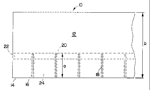
An ink knife 10 shown in Figs 1 to 3 essentially consists
of a metal plate 12 of spring steel which has a width b
of 90 mm and a thickness d of 3.5 mm. Starting from a
working edge 14, transverse grooves 16 running parallel
are cut out at a right angle and have a depth t of 1.5 mm
and a width c of 2.5 mm. The transverse grooves extend
over a distance a of approximately 35 mm in relation to
width b of the metal plate 12.
In the longitudinal centre plane of the transverse
grooves 16 runs a slot 18 produced by laser beam of 35 mm
length and
CA 02235255 1998-04-17
_ 7 _
0.015 mm width and 2 mm depth which serves to form the
blades.
In the area of the blind ends 20 of the transverse grooves
16, parallel to working edge 14, runs a recessed weakening
groove' 22 of circle-segment cross section. This has a
radius of curvature of approximately 5 mm and is cut 1.5 mm
deep, as are the transverse grooves 16. Thanks to this
weakening groove 22 the blades 24, which form an ink zone
width f, can move vertically to the plane of metal plate 12
with little use of force.
Fig 4 shows more clearly the slot 18 of width s 0.015 mm
formed by laser beam between the blades 24. The transverse
grooves 16, again rectangular in cross section, are filled
with an elastic mass 26, in the present case an acid-
resistant silicon mass. An angled scraper 38 (fig 5) is
attached to the blades with an adhesive layer 28. Only the
first leg 30 of this angled scraper is visible in Fig. 4.
If the right blade 24 is pushed into the position 32 shown
by dotted lines, for example by an adjustment screw not
shown, the adjacent centre blade 24 is not moved with it in
sympathy because the broad transverse groove 16 has a
compensatory effect. If the transverse groove 16 were only
narrow, the adjacent blade 24 would be moved in sympathy.
The narrow slot 18 however persists even when the right
blade 24 is moved. The residual material thickness d-t in
the area of working edge 14 is sufficiently large to keep
slot 18 unchangingly narrow when a blade 24 is moved in the
direction of the knife plane. In other words the adjustment
of the blades to change the quantity of ink supplied is
never so great that adjacent blades 24 shear away from each
other and no longer form slot 18.
Fig 5 shows an ink knife 10 adjusted to an ink duct roller
34. The blades of the ink knife 10, which is over 2 mm
CA 02235255 1998-04-17
- g _
thick, are cut out by two longitudinal weakening grooves 22
of circle-segment cross section running parallel to the
working edge 14. The blades 24 are thus more mobile in the
direction of arrow 36.
On the side of the blades 24 facing away from the ink duct
roller 34, an angled scraper 38 is glued by its first leg 30
on to blades 24. The leg 40 of angled scraper 38 projecting
freely over 3 to 5 cm is folded about an angle a. of slightly
over 40~.
To summarise it can be found that in particular the
following advantages can be achieved with the present
invention:
- A metal plate 12 for production of an ink knife 10 has
a thickness d of over 2 mm, preferably over 3 mm. This
avoids the deformation of the blades 24 on adjustment.
The screws require no support plate.
- Thanks partly to a longitudinal weakening groove 22,
the relatively thick blades are mobile to the required
extent in the area of working edge 14.
- The transverse grooves allow a very narrow slot which
can easily be produced with a laser beam and which can
be adapted to the viscosity of the ink.
- The broad transverse grooves allow, without mechanical
effect on the adjacent blades, the arrangement of an
angled scraper 38 which is glued to the side of the
metal plate 12 facing away from the ink duct roller 34.