Language selection

Search

Patent 2235793 Summary

Third-party information liability

Some of the information on this Web page has been provided by external sources. The Government of Canada is not responsible for the accuracy, reliability or currency of the information supplied by external sources. Users wishing to rely upon this information should consult directly with the source of the information. Content provided by external sources is not subject to official languages, privacy and accessibility requirements.

Claims and Abstract availability

Any discrepancies in the text and image of the Claims and Abstract are due to differing posting times. Text of the Claims and Abstract are posted:

  • At the time the application is open to public inspection;
  • At the time of issue of the patent (grant).
(12) Patent Application: (11) CA 2235793
(54) English Title: ENERGY-ABSORBING DEVICE
(54) French Title: DISPOSITIF A ABSORPTION D'ENERGIE
Status: Deemed Abandoned and Beyond the Period of Reinstatement - Pending Response to Notice of Disregarded Communication
Bibliographic Data
(51) International Patent Classification (IPC):
  • F16F 07/12 (2006.01)
  • B60R 19/04 (2006.01)
  • B61F 19/04 (2006.01)
(72) Inventors :
  • NORH, MATTHIAS (Germany)
  • BAYER, FRANZ JOSEF (Germany)
  • WERNER, FRIEDRICH (Germany)
  • RIEGLER, MANFRED (Germany)
(73) Owners :
  • ABB DAIMLER-BENZ TRANSPORTATION (TECHNOLOGY) GMBH
  • DAIMLERCHRYSLER RAIL SYSTEMS GMBH
(71) Applicants :
  • ABB DAIMLER-BENZ TRANSPORTATION (TECHNOLOGY) GMBH (Germany)
  • DAIMLERCHRYSLER RAIL SYSTEMS GMBH (Germany)
(74) Agent: SMART & BIGGAR LP
(74) Associate agent:
(45) Issued:
(22) Filed Date: 1998-04-24
(41) Open to Public Inspection: 1998-10-25
Examination requested: 2003-01-09
Availability of licence: N/A
Dedicated to the Public: N/A
(25) Language of filing: English

Patent Cooperation Treaty (PCT): No

(30) Application Priority Data:
Application No. Country/Territory Date
197 17 473 (Germany) 1997-04-25

Abstracts

English Abstract


An energy-absorbing device, particularly for rolling
stock to provide protection therefor when potentially
damaging impact occurs, includes first and second tubular
elements which are fitted into one another and which are of
unlike material.


French Abstract

Dispositif à absorption d'énergie visant à offrir une protection contre les impacts potentiellement dommageables pour le matériel roulant, en particulier. Il est constitué d'un premier et d'un second éléments tubulaires d'un matériau dissemblable ajustés l'un dans l'autre.

Claims

Note: Claims are shown in the official language in which they were submitted.

The embodiments of the invention in which an exclusive
property or privilege is claimed are defined as follows:
1. An energy-absorbing device comprising first and
second tubular elements fitted into one another and being of
unlike material.
2. The energy-absorbing device as defined in claim 1,
wherein said first tubular element comprises a trigger
portion at which deformation starts upon application of
energy to said device.
3. The energy-absorbing device as defined in claim 1,
wherein said first tubular element is one of plastic and
ceramic.
4. The energy-absorbing device as defined in claim 3,
wherein said first tubular element is of a composite
material.
5. The energy-absorbing device as defined in claim 4,
wherein said composite material is a fiber composite material
formed of a laminate and a matrix.
6. The energy-absorbing device as defined in claim 5,
wherein said laminate is selected from the group consisting
-9-

of fiber glass, carbon fiber, natural fiber, synthetic fiber
material and a combination thereof.
7. The energy-absorbing device as defined in claim 5,
wherein said matrix is one of a Duroplast and a thermoplast.
8. The energy-absorbing device as defined in claim 1,
wherein said second tubular element has an end provided with
a flange for securement to a rigid frame; said second tubular
element further having a guide element for guiding said
second tubular element in a rolling deformation thereof upon
application of energy.
9. The energy-absorbing device as defined in claim 1,
wherein said first tubular element is a metal.
10. The energy-absorbing device as defined in claim 9,
wherein said metal is selected from the group consisting of a
steel alloy and an aluminum alloy.
11. The energy-absorbing device as defined in claim 1,
further comprising an impact plate attached to said first and
second tubular elements for transmitting energy from said
impact plate to said first and second tubular elements.
- 10 -

12. The energy-absorbing device as defined in claim 1,
wherein said second tubular element includes means for
effecting one of a rolling deformation, a buckling
deformation and a looping deformation of said second tubular
element upon application of energy.
13. The energy-absorbing device as defined in claim 1,
wherein said first tubular element is fitted into said second
tubular element.
14. The energy-absorbing device as defined in claim 1,
wherein said second tubular element is fitted into said first
tubular element.
15. The energy-absorbing device as defined in claim 1,
in combination with a parapet carrier; said parapet carrier
having an inner space and a supporting end wall bounding said
inner space; said second tubular element being attached to
said parapet carrier and being positioned partially inside
and partially outside said inner space; said first tubular
element being fitted into said second tubular element and
being positioned partially inside and partially outside said
inner space; said first tubular element having an end portion
formed as a trigger at which deformation starts upon
application of energy to said device; said trigger adjoining
- 11 -

said supporting end wall; said first tubular element being
adapted to be pushed into and to break up at said supporting
end wall upon application of energy.
16. The energy-absorbing device as defined in claim 1,
further comprising an impact plate attached to said first and
second tubular elements for transmitting energy from said
impact plate to said first and second tubular elements; said
first tubular element having an end portion formed as a
trigger at which deformation starts upon application of
energy to said impact plate; said trigger adjoining said
impact plate; said first tubular element being adapted to be
pushed into and to break up at said impact plate upon
application of energy to said impact plate.
- 12 -

Description

Note: Descriptions are shown in the official language in which they were submitted.


CA 0223~793 1998-04-24
CROSS REFERENCE TO RELATED APPLICATION
This application claims the priority of German
Application No. 197 17 473 filed April 25, 1997, which is
incorporated herein by reference.
BACKGROUND OF THE INVENTION
The invention relates to an energy-absorbing device,
part-Lcularly for rolling stock.
Energy-absorbing devices are used in vehicle technology
for taking up kinetic energy, for example, upon a damaging
impact caused by colliding with an obstruction. During such
an occurrence, the energy is absorbed in a controlled manner
by parts that are especially provided on the vehicle for such
a purpose.
In order to introduce new safety features in rolling
stock, for example, in the frontal area of a locomotive,
deforming regions must be provided which, in view of the
enorrnous mass of the train, are capable of absorbing high
amounts of energy. In particular the engineer's cabin must
be sufficiently protected during an impact. The space
required for such a purpose, however, is severely limited at
such a location so that ideally an existing construction
shouLd be used for installing an energy-absorbing device.
- 2

CA 0223~793 1998-04-24
The rigid parapet region in particular provides hollow-
chamber profiles with varied profile cross sections and a
high bending moment of inertia, which can only be used,
however, if the dimensions of the energy-absorbing device can
be adapted for installation. The energy-absorption device
may also be used in aviation, for example, in helicopters,
where it may be installed in the seat to protect the pilot if
hard impact occurs.
Steel tubes which absorb the energy by folding, tapering
or by means of a rolling bending are known and are described
in current text books such as Lang, K., Manual for the Metal
Forming Technology, (1975), Vol. 3, p. 211 ff and the
Ency,-lopedia for Materials Technology, VDI Press (1991), p.
1858 ff. Further, French E'ublished Patent Application 2 698
034 A1 and US Patent 4,829,979 disclose, for a similar
purp,5se, tubes made of a fiber-reinforced plastic, which
absorb energy by fiber/matrix breakages.
A comparison of the various materials as to their
energy-absorbing property shows that plastics are far
superior to metals. However, plastic materials have the
disadvantage in practice that force-locking connections with
other components can be macle only with very significant
expenditure, if at all.

CA 0223~793 1998-04-24
S ~ MU~RY OF THE INrVENTION
It is an object of the invention to provide an improved
energy-absorbing device which can absorb a large amount of
energy applied, for example, to vehicles and is of varied
construction.
This object and others to become apparent as the
specification progresses, is accomplished by the invention,
according to which, brief ly stated, the energy-absorbing
device, particularly for rolling stock to provide protection
therefor when potentially damaging impact occurs, includes
first and second tubular e]ements which are fitted into one
another and which are of unlike material.
It is an essential advantage of the invention that by
utilizing metal for one of the tubular elements, it is
possible to make a force-locking flange connection to the
hollow-chamber profiles in a simple manner. By inserting the
tubular elements of unlike material - usually a plastic tube
and a metal tube - into one another, it is possible to take
up high amounts of energy. In such an arrangement the metal
tube and the plastic tube -- which, for example, surrounds the
metal tube - will stabilize each other in case of damaging
impact, so that on the one hand, the buckling stability of
the metal tube is increasec~ by the plastic tube and the flow
properties during the deformation are improved and, on the
-- 4

CA 0223~793 1998-04-24
other hand, the plastic tube is guided accurately by the
metal tube.
Another essential advantage resides in that it is
possible in a simple way to adapt the structural design to
the predetermined component geometries of the carrier
elem~-nts owing to the varied wall thickness and cross section
of the metal and plastic tubes. This results in an optimal
use of the existing hollow spaces in the carrier elements.
BRIEF DESCRIE'TION OF THE DRAWINGS
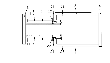
10 Figure 1 is a sectional side elevational view of a first
preferred embodiment having an internal metal tube.
Figure 2 is a sectiona,l side elevational view of a
second preferred embodiment having an external metal tube and
illu,trated before impact.
Figure 3 is a sectional side elevational view of the
second preferred embodiment illustrated after impact.
Figure 4 is a sectional side elevational view of a third
preferred embodiment having an external metal tube and
illustrated after impact.

CA 0223~793 1998-04-24
DESCRIPTION OF THE PREFERRED EMBODIMENTS
The energy-absorbing device shown in Figure 1 has an
outer plastic tubular element 1 which is attached, for
example, to a parapet carrier 3 by a connecting flange 21 of
an inner, metal tubular element 2. A guide element 22 is
used at the flange or as a part thereof to ensure that the
tubular element 2 is guided in a straight line during a
deformation. The tubular element 1 is fitted over the
tubular element 2 up to the guide element 22 and is supported
by the tubular element 2 without being additionally attached.
Upon damaging impact, the impact force is transmitted via the
guide element 22 to the flange 21 and the parapet carrier 3.
At its end the tubular element 1 has a "trigger" 11 which may
be wedge-shaped and which contacts an impact plate 5 attached
to the tubular element 2. The trigger 11 is inserted
purposely as starting point for the breakage in the tubular
element 1. Upon damaging impact, the tubular element 1
breaks off progressively, ~starting at the trigger 11. The
impact plate 5 ensures an even introduction of the force into
both tubular elements 1 and 2. The energy is absorbed by the
tubular element 2 via the deformation region 23 in a
progressive "rolling-off" motion of the tube, while the
energy is absorbed by the tubular element 1 by the breakage
- 6 -

CA 0223~793 1998-04-24
of a progressive breakage zone which is provided for this
purpose and which starts at: the trigger 11.
In second embodiment according to Figure 2 the energy-
absorbing device has a metal tubular element 2 which
surrounds the plastic tubular element 1. The trigger 11
forming part of the tubular element 1 is located inside the
parapet carrier 3, at a support wall 4. Figure 3 shows the
progression of breakage when damaging impact occurs.
Starting with the trigger 11, the tubular element 1
progressively breaks off at: the support wall 4. It is an
advantage of this arrangement that the material that breaks
off remains inside the hollow space of the parapet carrier 3.
The rolling bending of the tubular element 2 is deliberately
controlled by the guide element 22 and the inner tubular
element 1. Owing to the fact that the tubular elements 1 and
2 have unlike thicknesses, it is possible to control the
force transmission in a purposeful way to the individual
elements of the parapet carrier 3. If, for example, the
support 4 cannot be realized for structural reasons, then the
Figure 1 solution where the metal tubular element 2 is on the
inside can be readily used instead.
Figure 4 illustrates a further embodiment of an energy-
absorbing device in which t:he metal tubular element 2 is
adapted for particularly high energy-absorption. In the zone
24 a further deformation is added to the rolling deformation;
- 7 -

CA 0223~793 1998-04-24
such an additional deformalion is effected by a multiple
buck~Ling of the metal. In this arrangement either the
support wall 4 is installed offset toward the front as shown,
or the energy-absorbing device travels long deformation
paths.
The tubular element 1 may be of a plastic and/or ceramic
material or composite material formed of a laminate and a
matrix. The laminate may be fiber glass, carbon fiber,
natural fiber, synthetic f:iber material or a combination
thereof. The matrix may be a Duroplast or a thermoplast.
The tubular element 2 may be of metal, such as a steel alloy
or an aluminum alloy.
The invention is not :Limited to the described
embodiments; rather, it encompasses other types of
deformation of the metal tubular element 2, such as a looping
deformation which may deve:Lop by means of a partial foaming
of the hollow space in the carrier.
It will be understood that the above description of the
present invention is susceptible to various modifications,
changes and adaptations, and the same are intended to be
comprehended within the meaning and range of equivalents of
the appended claims.

Representative Drawing
A single figure which represents the drawing illustrating the invention.
Administrative Status

2024-08-01:As part of the Next Generation Patents (NGP) transition, the Canadian Patents Database (CPD) now contains a more detailed Event History, which replicates the Event Log of our new back-office solution.

Please note that "Inactive:" events refers to events no longer in use in our new back-office solution.

For a clearer understanding of the status of the application/patent presented on this page, the site Disclaimer , as well as the definitions for Patent , Event History , Maintenance Fee  and Payment History  should be consulted.

Event History

Description Date
Application Not Reinstated by Deadline 2005-04-25
Time Limit for Reversal Expired 2005-04-25
Deemed Abandoned - Failure to Respond to Maintenance Fee Notice 2004-04-26
Letter Sent 2003-02-11
Amendment Received - Voluntary Amendment 2003-01-29
All Requirements for Examination Determined Compliant 2003-01-09
Request for Examination Requirements Determined Compliant 2003-01-09
Request for Examination Received 2003-01-09
Letter Sent 2001-05-23
Inactive: Multiple transfers 2001-04-19
Letter Sent 2000-10-06
Inactive: Multiple transfers 2000-09-08
Inactive: Correspondence - Transfer 1999-01-14
Inactive: Courtesy letter - Evidence 1998-12-22
Inactive: Single transfer 1998-11-04
Application Published (Open to Public Inspection) 1998-10-25
Inactive: IPC assigned 1998-08-03
Classification Modified 1998-08-03
Inactive: IPC assigned 1998-08-03
Inactive: First IPC assigned 1998-08-03
Inactive: IPC assigned 1998-07-30
Inactive: Courtesy letter - Evidence 1998-07-14
Inactive: Applicant deleted 1998-07-08
Inactive: Filing certificate - No RFE (English) 1998-07-08
Application Received - Regular National 1998-07-06

Abandonment History

Abandonment Date Reason Reinstatement Date
2004-04-26

Maintenance Fee

The last payment was received on 2003-04-16

Note : If the full payment has not been received on or before the date indicated, a further fee may be required which may be one of the following

  • the reinstatement fee;
  • the late payment fee; or
  • additional fee to reverse deemed expiry.

Patent fees are adjusted on the 1st of January every year. The amounts above are the current amounts if received by December 31 of the current year.
Please refer to the CIPO Patent Fees web page to see all current fee amounts.

Owners on Record

Note: Records showing the ownership history in alphabetical order.

Current Owners on Record
ABB DAIMLER-BENZ TRANSPORTATION (TECHNOLOGY) GMBH
DAIMLERCHRYSLER RAIL SYSTEMS GMBH
Past Owners on Record
FRANZ JOSEF BAYER
FRIEDRICH WERNER
MANFRED RIEGLER
MATTHIAS NORH
Past Owners that do not appear in the "Owners on Record" listing will appear in other documentation within the application.
Documents

To view selected files, please enter reCAPTCHA code :


To view images, click a link in the Document Description column (Temporarily unavailable). To download the documents, select one or more checkboxes in the first column and then click the "Download Selected in PDF format (Zip Archive)" or the "Download Selected as Single PDF" button.

List of published and non-published patent-specific documents on the CPD .

If you have any difficulty accessing content, you can call the Client Service Centre at 1-866-997-1936 or send them an e-mail at CIPO Client Service Centre.

({010=All Documents, 020=As Filed, 030=As Open to Public Inspection, 040=At Issuance, 050=Examination, 060=Incoming Correspondence, 070=Miscellaneous, 080=Outgoing Correspondence, 090=Payment})


Document
Description 
Date
(yyyy-mm-dd) 
Number of pages   Size of Image (KB) 
Representative drawing 1998-11-09 1 4
Abstract 1998-04-23 1 9
Drawings 1998-04-23 2 28
Description 1998-04-23 7 215
Claims 1998-04-23 4 101
Filing Certificate (English) 1998-07-07 1 174
Courtesy - Certificate of registration (related document(s)) 1999-03-02 1 117
Reminder of maintenance fee due 1999-12-28 1 113
Courtesy - Certificate of registration (related document(s)) 2000-10-05 1 120
Reminder - Request for Examination 2002-12-26 1 113
Acknowledgement of Request for Examination 2003-02-10 1 173
Courtesy - Abandonment Letter (Maintenance Fee) 2004-06-20 1 175
Correspondence 1998-07-13 1 28
Correspondence 1998-12-21 1 14