Language selection

Search

Patent 2235915 Summary

Third-party information liability

Some of the information on this Web page has been provided by external sources. The Government of Canada is not responsible for the accuracy, reliability or currency of the information supplied by external sources. Users wishing to rely upon this information should consult directly with the source of the information. Content provided by external sources is not subject to official languages, privacy and accessibility requirements.

Claims and Abstract availability

Any discrepancies in the text and image of the Claims and Abstract are due to differing posting times. Text of the Claims and Abstract are posted:

  • At the time the application is open to public inspection;
  • At the time of issue of the patent (grant).
(12) Patent Application: (11) CA 2235915
(54) English Title: OPTICAL SIGNAL AMPLIFICATION CONTROL SYSTEM
(54) French Title: SYSTEME DE COMMANDE D'AMPLIFICATION DE SIGNAL OPTIQUE
Status: Deemed Abandoned and Beyond the Period of Reinstatement - Pending Response to Notice of Disregarded Communication
Bibliographic Data
(51) International Patent Classification (IPC):
  • H04J 14/02 (2006.01)
(72) Inventors :
  • HARANO, HIROSHI (Japan)
  • AMIMOTO, MASANAO (Japan)
(73) Owners :
  • NEC CORPORATION
(71) Applicants :
  • NEC CORPORATION (Japan)
(74) Agent: SMART & BIGGAR LP
(74) Associate agent:
(45) Issued:
(22) Filed Date: 1998-04-24
(41) Open to Public Inspection: 1998-10-25
Examination requested: 1998-04-24
Availability of licence: N/A
Dedicated to the Public: N/A
(25) Language of filing: English

Patent Cooperation Treaty (PCT): No

(30) Application Priority Data:
Application No. Country/Territory Date
09-121505 (Japan) 1997-04-25

Abstracts

English Abstract


Disclosed is an optical signal amplification control system
for amplifying in the lump a wavelength-multiplexed signal that
several optical signals with different wavelengths to be transmitted
through an optical fiber cable are multiplexed, the system having:
means for detecting always the number of the different wavelengths
multiplexed in the wavelength-multiplexed signal; and means for
amplifying in the lump the wavelength-multiplexed signal; wherein
the optical signal amplification control system controls the
amplifying means to amplify in the lump the wavelength-multiplexed
signal up to a desired level according to the detected number of the
different wavelengths.


French Abstract

Système de commande d'amplification de signal optique permettant d'amplifier en bloc un signal multiplexé en longueur d'onde de façon que plusieurs signaux de différentes longueurs d'onde à transmettre sur un câble à fibres optiques soient multiplexés. Le système comprend : des moyens de détecter toujours le nombre de différentes longueurs d'onde multiplexées dans le signal multiplexé en longueur d'onde et des moyens d'amplifier en bloc le signal multiplexé en longueur d'onde; le système de commande d'amplification du signal optique commandant les moyens d'amplification afin d'amplifier en bloc le signal multiplexé en longueur d'onde jusqu'à un niveau désiré selon le nombre détecté de différentes longueurs d'onde.

Claims

Note: Claims are shown in the official language in which they were submitted.

-8-
What is claimed is:
1. An optical signal amplification control system for
amplifying in the lump a wavelength-multiplexed signal that several
optical signals with different wavelengths to be transmitted through
an optical fiber cable are multiplexed, comprising:
means for detecting always the number of said different
wavelengths multiplexed in said wavelength-multiplexed signal; and
means for amplifying in the lump said wavelength-multiplexed
signal;
wherein said optical signal amplification control system
controls said amplifying means to amplify in the lump said
wavelength-multiplexed signal up to a desired level according to said
detected number of said different wavelengths.
2. An optical signal amplification control system, according
to claim 1, wherein:
said wavelength number detecting means comprises means for
separating part of said wavelength-multiplexed signal to be
transmitted, means for dividing said separated part of said
wavelength-multiplexed signal into lights with different
wavelengths, and means for counting said number of said different
wavelengths multiplexed in said wavelength-multiplexed signal by
detecting said divided lights with different wavelengths.
3. An optical signal amplification control system, according
to claim 2, wherein:
said separating means comprises an arrayed wave guide (AWG),

-9-
and said counting means comprises an arrayed photodetector.
4. An optical signal amplification control system, according
to claim 1, wherein:
said amplifying means comprises an excitation laser light
source, a WDM optical coupler to multiplex the excitation light from
said excitation laser light source with said wavelength-multiplexed
signal, and an erbium-doped fiber.
5. An optical signal amplification control system, according
to claim 1, further comprising:
means for feedback-controlling said amplifying means to provide
said wavelength-multiplexed signal to be output with said desired
level according to said detected number of said different wavelengths
while monitoring the output level after amplification.
6. An optical signal amplification control system, according
to claim 5, wherein:
said feedback-controlling means determines said desired level
according to said detected number of said different wavelengths and
controls said amplifying means to amplify in the lump said
wavelength-multiplexed signal up to said desired level.

Description

Note: Descriptions are shown in the official language in which they were submitted.


CA 0223~91~ 1998-07-21
OPTICAL SIGNAL AMPLIFICATION CONTROL SYSTE~
F'T~T.T~ r~F 'r~ TNVT~'N'rTt~N
This invention relates to an optical signal amplification
control system for amplifying wavelength-multiplexed optical signal
withdifferentwavelengths tobetransmitted through an opticalfiber
cable, and more particularly to, an optical signal amplification
control system used in amplifying wavelength-multiplexed optical
signal in the lump.
RArKr.~7nrTNn ~F 'rTr~ TNVT'NmTnN
It is well known that an optimum output power of optical signal
is required in the long-distance transmission through an optical
fiber cable since the output power to be too low or high causes a
S trouble.
Therefore, in the long-distance transmission of an optical
signal through an optical fiber cable, a wavelength-multiplexed
signal is amplified in the lump to get an optimum output power ~y
using repeating amplifiers placed at several repeating points.
The first one of conventional amplification control systems
is operated by storing apredetermined referencelevel in a repeating
amplifier, amplifying an optical signal to be input up to the
reference level, then outputting it.
The second system is operated by transmitting wavelength
2s multiplexing number information from a transmitting end to a
repeating amplifier, conducting the amplifying of the repeating
amplifier according to the wavelength multiplexing number
information.

CA 0223~9l~ l998-07-2l
Meanwhile, in such a conventional optical signal amplification
control system, the whole output power of a wavelength-mul~iplexed
optical signal is controlled to be constant even when amplifying the
optical signal where several signals with different wavelengths are
s wavelength-multiplexed.
However, in such controlling, the output power per each signal
(wavelength) must be varied depending upon the number of multiplexed
wavelengths. Namely, the larger the number of multiplexed
wavelengths is, the more the light output power per one waveleng.h
o is reduced. The optimum output power per one wavelength must be
varied depending upon the number of multiplexed wavelengths.
Thus, it is desired that a value of optimum output power can
be determined according to the wavelength multiplexing number
information when amplifying awavelength-multiplexed signal. Also,
15 it is desired that a value of optimum output power can be changed
on real time according to a variation in the number of multiplexed
wavelengths in such optical communication that the number of
multiplexed wavelengths may be varied. However, the first system
cannot be adapted to the variation in number of multiplexed
20 wavelengths.
The second system requires transmitting wavelength
multiplexing number information from a transmitting end to a
repeating amplifier, thereby increasing the guantity of information
to be transmitted through the optical fiber cable as well as
25 complicating the system that much.
Also, when a light-wave network using only light is constructed
in the future, the number of multiplexed wavelengths to be
transmittedthroughanopticalfibercablewillbedynamicallyvaried

CA 0223~91~ 1998-07-21
-3 -
In such case, the number of wavelengths in the second system is very
difficult to manage.
Furthermore, wrong wavelength number information may be
transmitted due to a noise etc. If the second system is controlled
5 by such wrong information, the transmission error of an optical
signal may occur.
.'~rTMMARY f~F ~r~TT~ TNVF'l~T'rTt~N
Accordingly, it is an object of the invention to provide an
o optical signal amplification control system thatcan conductoptimum
controls on output power according to the number of multiplexed
wavelengths without transmitting wavelength multiplexing number
information from a transmitting end.
It is a further object of the invention to provide an optical
~s signal amplification control system that can conduct optimum
controls on output power on real time even when the number of
wavelengths in a wavelength-multiplexed optical signal to be input
is dynamically varied.
According to the invention, an optical signal amplification
20 control system for amplifying in the lump a wavelength-multiplexed
signal that several optical signals with different wavelengths to
be transmitted through an optical fiber cable are multiplexed,
comprises:
means for detecting always the number of the different
2S wavelengths multiplexed in the wavelength-multiplexed signal; and
means for amplifying in the lump the wavelength-multiplexed
signal;
wherein the optical signal amplification control system

CA 0223~9l~ l998-07-2l
controls the amplifying means to amplify in the lump the
wavelength-multiplexed signal up to a desired level accordi~g to the
detected number of the different wavelengths.
R~ T F~ nF.~r~ T Pl'T~N nF 'T'~TF n~ AWTN(~
The invention will be explained in more detail in conjunction
with the appended drawings, wherein:
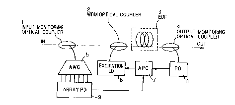
FIG.lisablockdiagramshowinganopticalsignalamplification
control system in a preferred embodiment according to the invention.
nF~ TPrrTtlN nF l'~F PRFFF~FT7 FMR~nTMFN'r.
An optical signal amplification control system in thepreferred
embodiment will be explained in FIG.l.
Referring to FIG.l, 1 is an input-monitoring optical coupler,
15 2 iS a WDM (wavelength division multiplex) optical coupler for
multiplexing an input signal and excitation laser light, and 3 is
an erbium-doped fiber (EDF) which is obtained by doping erbium ion
into an optical fiber and amplifies a 1.55 ~m band optical signal
when 1.48~m excitation light is supplied thereinto.
Further, 4 is an output-monitoring optical coupler, 5 is an
arrayed wave guide (AWG) for demultiplexing wavelength-multiplexed
light to be input into lights with different wavelengths, 6 is an
excitation laser light source (hereinafter referred to as
'excitation LD'), 7 is an automatic output power control (APC)
25 circuit, 8 is a photodetector (PD), and 9 is an arrayed photodetector
(hereinafter referred to as 'array PD').
Meanwhile, a wavelength number detecting means, which is
defined herein, is composed of the input-monitoring optical coupler

CA 0223~9l~ l998-07-2l
1, AWG 5 and the array PD 9. Also, an amplifying means, which is
defined herein, is composed of the excitation LD 6, the WDM-optical
coupler 2 and the erbium-doped fiber 3. Further, the control of the
amplifying means according to thenumber of multiplexed wavelengths,
5 which is defined herein, is conducted by the output-monitoring
optical coupler 4 and the APC circuit 7 to which wavelength number
information is input from the wavelength number detecting means.
In operation, an optical signal that several signals with
different wavelengths are multiplexed (wavelength-multiplexed
o signalJ is input to the input side (IN), and then part of the
wavelength-multiplexed signal is separated from its main signal by
the input-monitoring optical coupler 1, input to the arrayed wave
guide (AWG) 5.
The arrayed wave guide (AWG) 5 divides the wavelength-
15 multiplexedsignal input thereto into several signals with differentwavelengths, and the divided several signals with different
wavelengths are received, as they are, by the arrayed photodetector
(array PD) 9.
Thus, the number of wavelengths in the wavelength-multiplexed
20 signal to be input to the input side (IN) can be detected.
Meanwhile, theinput-monitoringopticalcouplerl, arrayedwave
guide (AWG) 5 and array PD 9 can be operated on real time. Therefore,
even when the number of wavelengths in the wavelength-multiplexed
signal to be input to the input side (IN) can be varied, the variation
2s can be detected on real time.
Then, information about the number of wavelengths (number of
signals) to be detected by the array PD 9 is sent to the APC circuit
7 to control automatically the light output power. The APC circuit

CA 0223~91~ 1998-07-21
7 selects an optimum output power according to the number of
wavelengths based upon this information, controlling the exeitation
LD 6 to provide the selected optimum output power.
On the other hand, the main signal is multiplexed with the
s optical output of the excitation LD 6 by the WDM optical coupler 2,
input to EDF 3, amplified by the EDF 3, then output through the
output-monitoring optical coupler 4 to the output side (OUT). At
this time, part of the output signal is divided by the output-
monitoring optical coupler 4, monitored of the output level by PD
8. The monitored information is then input to APC 7, thereby
conducting feedback control.
Thus, APC 7 determines an optimum value of whole amplification
level to the wavelength-multiplexed signal according to the
multiplexing wavelength number information obtained from the array
S PD 9, and feedback-controls the control current of the excitation
LD 6 so that the output signal level can have this optimum value while
monitoring the output signal level.
Although, in this embodiment, the wavelength number detecting
means is composed of the input-monitoring optical coupler 1, AWG 5
20 and the array PD 9, it is not limited to this composition. The
wavelength number detecting means may be any means that is composed
of means for separating part of a wavelength-multiplexed signal to
be transmitted, means for dividing the separated part of the
wavelength-multiplexed signal into lights with different
25 wavelengths, and means for detecting the divided lights with
different wavelengths to count the number of wavelengths.
Although, in this embodiment, the amplifying means is composed
of the excitation LD 6, theWDMoptical coupler 6 and theerbium-doped

CA 0223~91~ 1998-07-21
fiber 3, it is not limited to this composition. The amplifying means
may be any means that can amplify in the lump the wavelengtn-
multiplexed signal up to a desired level.
s Although the invention has been described with respect to
specific embodiment for complete and clear disclosure, the appended
claims are not to be thus limited but are to be construed as embodying
all modification and alternative constructions that may be occurred
to one skilled in the art which fairly fall within the basic teaching
o here is set forth.

Representative Drawing
A single figure which represents the drawing illustrating the invention.
Administrative Status

2024-08-01:As part of the Next Generation Patents (NGP) transition, the Canadian Patents Database (CPD) now contains a more detailed Event History, which replicates the Event Log of our new back-office solution.

Please note that "Inactive:" events refers to events no longer in use in our new back-office solution.

For a clearer understanding of the status of the application/patent presented on this page, the site Disclaimer , as well as the definitions for Patent , Event History , Maintenance Fee  and Payment History  should be consulted.

Event History

Description Date
Inactive: IPC expired 2013-01-01
Inactive: IPC from MCD 2006-03-12
Application Not Reinstated by Deadline 2002-06-25
Inactive: Dead - No reply to s.30(2) Rules requisition 2002-06-25
Deemed Abandoned - Failure to Respond to Maintenance Fee Notice 2002-04-24
Inactive: Abandoned - No reply to s.30(2) Rules requisition 2001-06-22
Inactive: S.30(2) Rules - Examiner requisition 2001-02-22
Application Published (Open to Public Inspection) 1998-10-25
Inactive: Single transfer 1998-09-08
Inactive: First IPC assigned 1998-07-29
Classification Modified 1998-07-29
Inactive: IPC assigned 1998-07-29
Inactive: Correspondence - Formalities 1998-07-21
Inactive: Filing certificate - RFE (English) 1998-07-09
Application Received - Regular National 1998-07-07
Request for Examination Requirements Determined Compliant 1998-04-24
All Requirements for Examination Determined Compliant 1998-04-24

Abandonment History

Abandonment Date Reason Reinstatement Date
2002-04-24

Maintenance Fee

The last payment was received on 2001-03-15

Note : If the full payment has not been received on or before the date indicated, a further fee may be required which may be one of the following

  • the reinstatement fee;
  • the late payment fee; or
  • additional fee to reverse deemed expiry.

Patent fees are adjusted on the 1st of January every year. The amounts above are the current amounts if received by December 31 of the current year.
Please refer to the CIPO Patent Fees web page to see all current fee amounts.

Fee History

Fee Type Anniversary Year Due Date Paid Date
Application fee - standard 1998-04-24
Request for examination - standard 1998-04-24
Registration of a document 1998-09-08
MF (application, 2nd anniv.) - standard 02 2000-04-24 2000-03-20
MF (application, 3rd anniv.) - standard 03 2001-04-24 2001-03-15
Owners on Record

Note: Records showing the ownership history in alphabetical order.

Current Owners on Record
NEC CORPORATION
Past Owners on Record
HIROSHI HARANO
MASANAO AMIMOTO
Past Owners that do not appear in the "Owners on Record" listing will appear in other documentation within the application.
Documents

To view selected files, please enter reCAPTCHA code :


To view images, click a link in the Document Description column. To download the documents, select one or more checkboxes in the first column and then click the "Download Selected in PDF format (Zip Archive)" or the "Download Selected as Single PDF" button.

List of published and non-published patent-specific documents on the CPD .

If you have any difficulty accessing content, you can call the Client Service Centre at 1-866-997-1936 or send them an e-mail at CIPO Client Service Centre.


Document
Description 
Date
(yyyy-mm-dd) 
Number of pages   Size of Image (KB) 
Description 1998-04-23 7 234
Abstract 1998-04-23 1 18
Drawings 1998-04-23 1 11
Claims 1998-04-23 2 63
Description 1998-07-20 7 241
Abstract 1998-07-20 1 18
Drawings 1998-07-20 1 11
Claims 1998-07-20 2 60
Representative drawing 1998-11-08 1 7
Filing Certificate (English) 1998-07-08 1 174
Courtesy - Certificate of registration (related document(s)) 1998-11-02 1 114
Reminder of maintenance fee due 1999-12-28 1 113
Courtesy - Abandonment Letter (R30(2)) 2001-09-03 1 172
Courtesy - Abandonment Letter (Maintenance Fee) 2002-05-21 1 183
Correspondence 1998-07-08 1 37
Correspondence 1998-07-20 12 380