Note: Descriptions are shown in the official language in which they were submitted.
CA 02236040 1998-04-28
GR 95 P 2097 P
Description
Sorting apparatus, in particular $or mail
The machine-readable postcodes which should be
specified on items of mail, such as letters, postcards,
packets and the like, as an identification for a
location, a postal district, a P0 box or a major
recipient, permit rapid, mechanical distribution of mail.
In this arrangement, sorting of the incoming items of
mail takes place with the aid of controllable conveyable-
article carriers which are each loadod, manually ormechanically, with an item of mail in special input
locations and then discharge said item of mail to a
sorting conta;n~r, or a correspo~;ng sorting compart-
ment, assigned to the respective postcode. Since, for
space-saving reasons, it is desired for both the input
locations and the sorting containers or sorting compart-
ments to be arranged in various planes, the cG"ve~dble-
item carriers circulating on conveying devices must, if
appropriate, also be capable of 8pann i ng various levels.
After transfer of the item of mail to the assigned
sorting container or the assigned sorting compartment,
the empty conveyable-article carrier can once again be
loaded with an item of mail when it passes an input
location.
US-A-3 300 026 discloses a sorting apparatus for
mail which has pairs of conveyable-article carriers which
circulate on a conveying device and are intended for
receiving, for transporting and for discharging, in a
controllable manner, the mail. The conveying device
comprises two cha;nR which circulate endlessly at a
distance from one another, are guided in a me~n~ring
fashion over correspon~;ng rollers and, on a plurality of
planes located one above the other, guide the co,.vayable-
article carriers past in each case one row with sorting
containers. The mean~ering progression of the cG~-veylng
device in a plurality of planes result~ in a relatively
large overall height of the sorting apparatus, with
CA 02236040 1998-04-28
- la -
corresponA;ngly poor accessibility to the sorting
containers arranged in the top planes.
CA 02236040 1998-04-28
W0 95/02468 discloses a sorting apparatus, in
particular for mail, which has a plurality of cG~eyable-
article carriers which circulate on a co~Oylng device
and are intended for receiving, for transporting and for
discharging, in a controllable manner, the cG"veyable
articles to assigned sorting containers. The conveyable-
article carriers are fastened on circulating transporting
carriages of the conveying device, $t being the case that
the transporting carriages, which are driven by an
endlessly circulating transporting cable, are guided, by
way of rollers, on two profiles which aro aligned at a
vertical distance from one another and extend in the
transporting direction. The transporting carriages
circulate, via a vertical deflection, in two planes, with
the result that, in each plane, they can be guided along
in each case two parallel rows with sorting cont~iners.
In the case of the conveying device of tho
sorting apparatus' disclosed by W0 95/02468, the
conveyable-article carriers which are loaded with
conveyable articles, for example, in a roar lo~;ng zone
of the bottom plane, are deflected forwards on the same
level and then transported past the sorting contA;ners
arranged in a row on the front side of the bottom plane.
In the region of the vertical deflection, the cG~v.-y-ble-
article carriers are then guided obliquely upwards intothe top plane and, there, are transported past the
sorting containers arranged in a row on the rear side. In
the region of the end side, the sorting containers are
then deflected forwards on the ~ame level and then
transported past the sorting conta;ners arranged in a row
on the front side. In the region of the vertical
deflection, the conveyable-article carriers are then
guided obliquely downwards into the bottom plane and,
there, are transported past the sorting conta;ners
arranged in a row on the rear side. In the region of the
vertical deflection, the two profiles for guiding the
transporting carriages and the transporting cable runj in
one case, obliquely from bottom to top and, in another
case, obliquely from top and to bottom in the opposite
CA 02236040 1998-04-28
- 2a -
direction. Guidance of the tran~porting cable over two
appropriately ~ized cable
CA 02236040 1998-04-28
wheels arranged in the region of the vertical deflection
would result in a greater overall length of the sorting
apparatus. Guidance of the transporting cable over a
plurality of deflection rollers arranged in the region of
the vertical deflection may avoid this increase in
overall length. On the other hand, the service life of
the transporting cable is influenced to a great extent by
the flexing of the cable which takes place as the cable
runs over the deflection rollers. Moreover, ayy~ ting
rl~nn;ng noise is produced when the transporting cable is
guided over a plurality of deflection rollers.
The invention specified in claim 1 has the
problem of improving, for the sorting apparatus which is
known from WO 95/02468, the guidance of the transporting
cable in the region of the vertical deflection, without
increasing the overall length in the process, in such a
way as to increase the service life of the transporting
cable and to reduce the r~nn;ng noise.
Besides sorting and distributing mail in public
post offices or central in-house mail departments of
large c~r~n;es, a sorting apparatus according to the
invention may also be used for comparable tasks, for
example, in storage systems or automated order-picking
systems, in the case of which goods or parts provided
with codings are fed to sorting containers, or sorting
compartments, assigned to the respective codings.
The invention is based on the f;n~ing that the
advantages in term~ of service life and quiet rllnn;ng
which can be achieved by guiding the transporting cable
over a large cable wheel can be combined with the
advantage~ in terms of low space requirements which can
be achieved by guiding the transporting cable over a
plurality of deflection rollers. For this purpose, the
transporting cable is guided over a wheel rim which, with
the omission of central mounting, has its inner circum-
ference mounted rotatably on a plurality of supporting
rollers.
CA 02236040 1998-04-28
Advantageous configuration~ of the invention are
~pecified in the subclaims.
The configuration according to claim 2 permits a
further reduction in the overall length of the ~orting
apparatus. The interengagement of the wheel rims results
in a reduction in the order of magnitude of the wheel-rim
diameter.
The development according to claim 3 facilitates
both the in~tallation and the removal of the two inter-
engaging whoel rims.
The configuration according to claim 4 provides
for a considerable improvement in term~ of the quiet
r~nn~ng of the sorting apparatus, in which ca~e,
according to claim 5, wheel-rim in~erts made of rubber in
particular have proven succe~sful.
An exemplary embodiment of the invention is
described in more detail hereinbelow and is illustrated
in the drawing, in which:
Figure 1 show~ a perspective illustration of a
conveyable-article carrier comprising a fixedly
arranged wall part and a movably arranged wall
part,
Figure 2 ~hows the operating principle of a co.lve~ing
device on which co,.vcyable-article carriers
according to Figure 1 circulate, said carriers
being fastened on transporting carriages,
Figure 3 shows a perspective illu~tration of two
modules, lined up side by ~ide, of a sorting
apparatus equipped with conveyable-article
carriers according to Figure 1 and with a
conveying device according to Figure 2,
Figure 4 ~hows a ~ide view of a sorting apparatu~
constructed from module~ according to Figure 3,
CA 02236040 1998-04-28
Figure 5 shows a plan view of the sorting apparatus
according to Figure 4,
Figure 6 shows a perspective illustration of the
guidance, over two planes, of the conveying
device of the sorting apparatus illustrated in
Figures 4 and 5,
Figure 7 shows the vertical deflection of the cG,.veying
device illustrated in Figure 6, with the
schematically illustrated guidance of the
transporting cable over two interengaging wheel
rims,
Figure 8 shows a plan view of a wheel rim which has its
inner circumference mounted rotatably on a
plurality of supporting rollers, and~5 Figure 9 show~ a radial section through the wheel rim
and a supporting roller of the arrangement
illustrated in Figure 8.
Figure 1 shows a perspective illustration of a
conveyable-article carrier which is designated as a whole
by FT and comprises a fixedly arranged wall part FW and
a movable wall part BW. In this arrangement, the movable
wall part BW can be pivoted about a pivot pin DA aligned
transversely with respect to the transporting direction
TR of the cG"verable-article carrier FT.
Figure 1 showR the closed position of the
co,,veyable-article carrier FT, in which the fixedly
arranged wall part FW and the movably arranged wall part
BW, each of which are curved outward, form a cross-
sectionally approximately V-shaped receiving pocket for
the co"v~y~ble articles. The closed position is secured
by a detent pawl SR which can be rotated about an axis
designated by A and can be released by actuating a
solenoid HM. If the detent pawl SR is released, then the
movable wall part BW is pivoted about the pivot pin DA
~uch that an ejection slit, which is open at the bottom
CA 02236040 1998-04-28
and belongs to the eo~eyable-article earrier FT, is
formed. In this arrangement, the bottom extension of the
mo~ably arranged wall part BW forms an ejeetion chute AR
which adjoins ~a$d ejection slit at the bottom and is
inclined counter to the transporting direction TR.
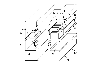
Figure 3 shows a perspeeti~e illustration of two
modules M1 and M2, lined up side by side, of a sorting
apparatus equipped with co.,-vdyablo-article earriers FT
aecording to Figure 1. In this arrangement, in each case
a total of five eon~syable-artiele earriers FT are fitted
on one transporting earriage TW, the latter being a
eonstituent part of a eG~vcylng deviee FE and eireulating
in two planes E1 and E2. Eaeh module M1 and M2 has, in
each plane E1 and E2, in eaeh ea~e two metal bearing
plates AB, on whieh sorting eontainers SB ean be lined up
closely side by side. It can be seen that the conveyable-
article carriers FT on the transporting carriages TW
circulate above the sorting conta;ner8 SB sueh that, upon
actuation of the detent pawl S~ (see Figure 1), the
cG"veyable articles (not illustrated speeifieally in
Figure 3) ean be ejeeted into a ~orting container SB
assigned to the respective eoding.
Figure 2 shows closer details of the conveying
device FE illustrated in Figure 3. In the cross section
illu~trated here, it ean be seen that the transporting
carriage TW iB guided, via rollers designated by R, on
two tubular profiles P exten~;ng in the transporting
direetion TR (see Figure 1). In this arrangement, the
profiles P, aligned parallel to one another at a vertieal
distance, are connected to one another, in rectilinear
regions of the cG..veying de~ice FE, via webs ST likewise
exten~;ng in the transporting direetion TR, Baid webB ST
being dispensed with in the eurved regions. A
transporting earriage TW iB dri~ren ~ria an endlessly
eireulating transporting eable TS, on whieh the
transporting earriage TW is fastened with the aid of a
driver MN. On the side loeated opposite the transporting
cable TS, the transporting carriage TW has a metal
supporting plate TB on whieh the indi~idual
CA 02236040 1998-04-28
- 6a -
con~eyable-article carrier~ FT are factened by the end
~ide
CA 02236040 1998-04-28
-- 7
and which also bears the detent pawls SK and the
associated solenoids HM. The metal supporting plate TB
functions in this arrangement as a securing means for the
pivot pins DA of the movable wall parts BW, while the
fixed wall parts FW of the individual cG~veyable-article
carriers FT are connected fixedly to the metal supporting
plate TB via end-side flanges F (see Figure 1).
Figures 4 and 5 show a side view and a plan view,
respectively, of a sorting apparatus made up of
individual modules M. In this arrangement, the individual
modules M correspond to the modules M1 and M2 illustrated
in Figure 3, but, in Figure 6, an additional feed belt
ZB, which is arranged beneath the bottom plane E1 and is
intended for providing empty sorting containers SB, is
also illustrated. Upon removal of a full sorting
container SB from the plane El or the plane E2, said
sorting container can then be replaced by an empty
sorting container SB provided on the feed belt ZB.
In the illustration according to Figures 4 and 5,
a vertical deflection HU is located on the left-hand side
in front of the first module M, while an end-side input
module EM adjoins the last module M on the right-hand
side. It can be seen that, in the region of said input
module EM, the individual conveyable-article carriers FT
can be loaded from the rear, from the end side or from
the front, it being possible for lo~; ng to be carried
out manually or mechanically.
Figure 6 shows a vastly simplified schematic
illustration of the guidance of the conveying device FE
(see Figures 2 and 3) over the two planes E1 and E2. The
line L shows the spatial routing of the transporting
cable TS (see Figure 4), the transporting direction being
indicated by arrows TR. The guidance of the transporting
cable TS in the region of the vertical deflection HU is
indicated by two interengaging wheel rims RR1 and RR2. In
order to simplify the illustration, the guidance of the
tran~porting cable TS in the region of the input module
EM is
CA 02236040 1998-04-28
indicated by deflection roller~ U. In the case of the
actual embodiment, however, use is made here of a cable
wheel in the plane El and of a wheel rim in the plane E2.
In this case, the cable wheel in the plane El serves
simultaneously as a drive for the conveying device FE as
a whole (~ee Figure 2). The spatial routing of the
profiles P (see Figure 2) parallel to the line L cannot
be seen in Figure 6.
Figure 7 shows a vastly simplified schematic
illustration of the vertical deflection HU according to
Figure 6 in detail. It can be seen that the transporting
cable TS ~rrives in the transporting direction TR, from
right to left, on the rear side of the top plane E2,
[lacuna~ deflected, via the wheel rim RRl obliquely
forwards into the bottom plane E1 and, from there,
continues in the transporting direction TR, from left to
right. As it progresses, the transporting cable TS then
arrives in the transporting direction TR, from right to
left, on the rear side of the bottom plane E1 and is
deflected, via the wheel rim RR2, obliquely forwards into
the top plane E2 and then continue~ in the transporting
direction TR, from left to right.
The routing of the profiles P (see Figure 2) is
not illustrated in Figure 7. The profiles P, which are
necessary for guiding the transporting carriages TW (see
Figure 2) over the second wheel rim RR2 likewise run
through the interior of the first wheel rim RRl. The
diameters of the two interengaging wheel rims RRl and RR2
in this arrangement are selected such that the
transporting carriages TW, along with the conveyable-
article carriers FT fitted thereon (see Figure 2), can
run through the interior of the wheel rim RRl without
obstruction.
Figure 8 shows a plan view of the wheel rim RRl,
which has its inner circumference mounted rotatably on a
total of ten supporting rollers SR. In this arrangement,
in each case five supporting rollers SR, distributed over
a quarter-circle, are arranged on carriers TG which,
CA 02236040 1998-04-28
for their part, are fastened on the mac~;ne framework
(not illustrated specifically) such that they can be
ad~usted via slots LL.
Figure 9 shows a radial section through the wheel
rim RRl and a carrier roller TR, which is arranged
rotatably, via a ball bearing RL, on a spindle Z of the
carrier TG.
The section illustrated in Figure 9 also shows
that the carrying cable TS is guided over an insert E of
the wheel rim RRl. Quiet r~nn;ng is con~idera~ly improved
as a result, in particular the drivers MN for the
transporting carriages TW (see Figure 2) being guided
over the rubber insert E without rattling.
It can be seen from Figure 8 that, in terms of
the service life of the transporting cable TS which can
be expected, guidance of the transporting cable TS over
the wheel rim RRl can be equated with guidance over a
centrally mounted cable wheel. On the other hand, the
arrangement which i~ illustrated in Figure 8 has the
advantage that the second wheel rim RR2 (see Figure 7) as
well as the profiles P and the transporting carriages TW
with the conveyable-article carriers FT (see Figure 2)
can be guided through the first wheel rim RRl.