Language selection

Search

Patent 2236059 Summary

Third-party information liability

Some of the information on this Web page has been provided by external sources. The Government of Canada is not responsible for the accuracy, reliability or currency of the information supplied by external sources. Users wishing to rely upon this information should consult directly with the source of the information. Content provided by external sources is not subject to official languages, privacy and accessibility requirements.

Claims and Abstract availability

Any discrepancies in the text and image of the Claims and Abstract are due to differing posting times. Text of the Claims and Abstract are posted:

  • At the time the application is open to public inspection;
  • At the time of issue of the patent (grant).
(12) Patent Application: (11) CA 2236059
(54) English Title: LOCKSET
(54) French Title: SERRURE
Status: Deemed Abandoned and Beyond the Period of Reinstatement - Pending Response to Notice of Disregarded Communication
Bibliographic Data
(51) International Patent Classification (IPC):
  • E05B 9/04 (2006.01)
  • E05B 13/10 (2006.01)
  • E05B 15/00 (2006.01)
  • E05B 63/00 (2006.01)
(72) Inventors :
  • ARMSTRONG, STEVEN (United States of America)
(73) Owners :
  • NEWFREY LLC
(71) Applicants :
  • NEWFREY LLC (United States of America)
(74) Agent: NORTON ROSE FULBRIGHT CANADA LLP/S.E.N.C.R.L., S.R.L.
(74) Associate agent:
(45) Issued:
(22) Filed Date: 1998-04-27
(41) Open to Public Inspection: 1998-10-29
Examination requested: 2003-04-14
Availability of licence: N/A
Dedicated to the Public: N/A
(25) Language of filing: English

Patent Cooperation Treaty (PCT): No

(30) Application Priority Data:
Application No. Country/Territory Date
08/819,175 (United States of America) 1997-04-29

Abstracts

English Abstract


A lockset having a bezel surrounding the
cylinder lock which can be rotated when the door is
unlocked to relock the door.


French Abstract

Serrure comportant autour du cylindre un anneau qu'on peut faire tourner pour reverrouiller la porte quand elle est déverrouillée.

Claims

Note: Claims are shown in the official language in which they were submitted.

CLAIMS
1. A lockset comprising
a keyed cylinder including an axially extending
torque blade,
a support bracket mountable on a door,
a cylindrical bezel,
means for rotatably supporting said cylindrical
bezel between said keyed cylinder and said support
bracket,
said support bracket including an annular
surface facing said bezel having an axially extending
notch therein located at a door locked location,
said bezel including an annular surface facing
said support bracket annular surface,
a plurality of axially projecting teeth on said
bezel annular surface, and
a cam element including
a hole for receiving said torque blade so
that said cam element can be slidably displaced along
said torque blade and so that said cam element will
rotate with said torque blade,
a first tooth projecting axially towards
said support bracket annular surface for riding on
said support bracket annular surface when the door is
unlocked and selectively configured for insertion
into said axially extending notch when the door is
locked and
a seconds tooth projecting axially towards
said bezel annular surface and selectively configured
to engage one of said bezel teeth in the event that
said bezel is rotated while said second tooth is
riding on said annular surface, said second tooth and
said bezel teeth being axially spaced when said first
tooth is at the door locked position,
a spring for biasing said cam element towards
said support bracket,
said hole being selectively configured so that
-5-

said cam element can selectively move so that said
first tooth can either enter said notch or ride on
the annular surface of said support bracket,
whereby said bezel can be rotated when the door
is unlocked so that one of said bezel teeth will
engage said cam second tooth which will be located on
said support bracket annular surface to thereby
rotatively drive said cam element until said first
tooth is forced into said notch by said spring.
2. A lockset according to claim 1, wherein said
support bracket includes a second axially extending
notch therein located at a second door locked
location.

Description

Note: Descriptions are shown in the official language in which they were submitted.


CA 022360~9 1998-04-27
SPECIFICATION
LOCKSET
BACKGROUND OF THE INVENTION
The present invention relates to locksets and
more particularly to locksets which include an
exterior lock which is key operable but which can be
relocked from the exterior by rotating a rotatable
bezel.
Conventional deadbolts are key operated from
the outside, whether opening or locking the door.
When it is dark outside the door, finding the key
hole can be difficult. To obviate this problem,
deadbolts have been designed to permit exterior
locking without a key. U.S. Patents numbered
5,150,592 and 5,010,749 disclose locks which operate
in this manner.
It is an object of the present invention to
provide a simplified design which will permit
relocking without a key.
Other objects and advantages of the present
invention will become apparent from the following
portion of this specification and from the accompany-
ing drawings which illustrate in accordance with the
mandate of the patent statutes a presently preferred
embodiment incorporating the principles of the
invention.
BRIEF DESCRIPTION OF THE DRAWINGS
Referring to the drawings:
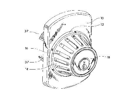
Figure 1 is an oblique front view of a deadbolt
made in accordance with the teachings of the present
invention;
Figure 2 is an oblique exploded view of a
portion of the deadbolt illustrated in Figure l;
Figure 3 is a front view of the deadbolt
portion shown in figure 1 with the deadbolt cylinder
and bezel portions removed;
Figure 4 is an oblique separated view showing

CA 022360~9 l998-04-27
a portion of the deadbolt shown in Figure 2 from the
other end; and
Figure 5 is a side elevational view of the cam
element when the door is in the unlocked position.
The deadbolt includes a decorative shroud 10
which has an annular outwardly projecting lip 12, a
conical rotatable bezel 14 which may have outwardly
extending grips 16 and a cylinder portion 18 which
holds the bezel on the shroud. The cylinder portion
18, which is received by a housing 20 (figure 2),
receives a "D" shaped torque blade 22 ~figure 3)
which passes through a circular hole 24 in a
compression spring 26, through a "D" shaped hole 27
in a cam element 28, through a circular hole 30 in a
cover 32 and freely through a large opening 34 in a
support bracket 36. The support bracket includes
upper and lower shield portions 37. A screw 38 which
passes through a suitable opening 40 in the cover and
into a suitable hole (not shown) in the housing traps
the cam element between the cover and the end of the
cylinder with a limited degree of axial movement.
For further details of a conventional deadbolt
cylinder please see U.S. Patent No. 5,317,889.
The end of the bezel adjacent the door has an
outer annular surface 42 which is located between the
annular lip 12 of the decorative shroud and a raised
annular lip 44 on the support plate 36 and engages
the support plate and an inner annular surface 43
which is slightly recessed. Located on this inner
annular surface and within the support plate raised
annular lip 44 are four 90~ spaced bezel teeth 46 (at
0~, 90~, 180~ and 270~) which extend toward the door.
Defined on the annular portion 50 of the surface of
the supporting plate within the annular lip 44 and
axially adjacent the inner annular surface are
located a pair of radial notches 52 (figure 3) which
are located about 30~ on either side of the 180~
-2-

CA 022360~9 1998-04-27
location. One of these notches is for left hand
operation and the other is for right hand operation.
The cam element 28, which rotates with the torque
blade 22, has a head portion 54 which is received
within the open end of the housing 22 and an arm
portion 56 which extends outwardly through a slot 58
defined in the end of the housing. The arm
terminates in a first tooth 60 which pro~ects axially
toward the annular portion 50 on the support plate
and which is shaped to be received by either of the
radial notches 52 and in a second tooth 62 which
projects axially toward the inner annular portion 43
on the bezel and which is shaped to be engaged and
rotatively displaced by any of the bezel teeth 46
when the bezel is rotated. When the deadbolt is
locked either by operating the key in the front lock
or by either doing the same thing on the interior
lock or operating an interior turn lever, the cam
element will be rotated with the torque blade whereby
the first cam tooth will be retracted from the
support plate notch that it is in when the door is
locked and rides along the flat surface of the
support plate until it becomes located at the 6:00
position illustrated in figure 3 (the cam is
forcefully displaced axially along the torque rod).
As shown in Figure 5, such movement is carried out by
the cam element pivoting slightly when the first
tooth rides on the surface of the support bracket.
In the event any of the four bezel teeth are in the
path of the second cam tooth 62 as the cam rotates to
this position the bezel will be rotated with the cam
element. The door can be relocked in a traditional
manner by operating either the key or the turn lever.
Additionally the door can be relocked from the
outside by rotating the bezel in the direction that
will return the cam to its initial position (the
bezel will only rotate in one direction). When the
-3-

CA 022360~9 1998-04-27
bezel is rotated, one of the bezel teeth will engage
the second cam tooth and rotatively drive the cam
back to its start position where the force of the
compression spring 26 will force the first tooth of
the cam into the notch on the support plate that
defines the initial cam position (door locked). At
this location the second cam tooth and the bezel
teeth become axially separated so that rotation of
the bezel has no function.
1 0 A: \508603US SPC

Representative Drawing
A single figure which represents the drawing illustrating the invention.
Administrative Status

2024-08-01:As part of the Next Generation Patents (NGP) transition, the Canadian Patents Database (CPD) now contains a more detailed Event History, which replicates the Event Log of our new back-office solution.

Please note that "Inactive:" events refers to events no longer in use in our new back-office solution.

For a clearer understanding of the status of the application/patent presented on this page, the site Disclaimer , as well as the definitions for Patent , Event History , Maintenance Fee  and Payment History  should be consulted.

Event History

Description Date
Inactive: IPC from MCD 2006-03-12
Time Limit for Reversal Expired 2005-04-27
Application Not Reinstated by Deadline 2005-04-27
Deemed Abandoned - Failure to Respond to Maintenance Fee Notice 2004-04-27
Letter Sent 2003-12-10
Inactive: Multiple transfers 2003-09-18
Letter Sent 2003-05-30
Request for Examination Requirements Determined Compliant 2003-04-14
Amendment Received - Voluntary Amendment 2003-04-14
Request for Examination Received 2003-04-14
All Requirements for Examination Determined Compliant 2003-04-14
Application Published (Open to Public Inspection) 1998-10-29
Classification Modified 1998-07-28
Inactive: First IPC assigned 1998-07-28
Inactive: IPC assigned 1998-07-28
Inactive: Filing certificate - No RFE (English) 1998-07-09
Filing Requirements Determined Compliant 1998-07-09
Application Received - Regular National 1998-07-08

Abandonment History

Abandonment Date Reason Reinstatement Date
2004-04-27

Maintenance Fee

The last payment was received on 2003-04-04

Note : If the full payment has not been received on or before the date indicated, a further fee may be required which may be one of the following

  • the reinstatement fee;
  • the late payment fee; or
  • additional fee to reverse deemed expiry.

Please refer to the CIPO Patent Fees web page to see all current fee amounts.

Fee History

Fee Type Anniversary Year Due Date Paid Date
Registration of a document 1998-04-27
Application fee - standard 1998-04-27
MF (application, 2nd anniv.) - standard 02 2000-04-27 2000-04-04
MF (application, 3rd anniv.) - standard 03 2001-04-27 2001-04-10
MF (application, 4th anniv.) - standard 04 2002-04-29 2002-04-08
MF (application, 5th anniv.) - standard 05 2003-04-28 2003-04-04
Request for examination - standard 2003-04-14
Owners on Record

Note: Records showing the ownership history in alphabetical order.

Current Owners on Record
NEWFREY LLC
Past Owners on Record
STEVEN ARMSTRONG
Past Owners that do not appear in the "Owners on Record" listing will appear in other documentation within the application.
Documents

To view selected files, please enter reCAPTCHA code :


To view images, click a link in the Document Description column. To download the documents, select one or more checkboxes in the first column and then click the "Download Selected in PDF format (Zip Archive)" or the "Download Selected as Single PDF" button.

List of published and non-published patent-specific documents on the CPD .

If you have any difficulty accessing content, you can call the Client Service Centre at 1-866-997-1936 or send them an e-mail at CIPO Client Service Centre.


Document
Description 
Date
(yyyy-mm-dd) 
Number of pages   Size of Image (KB) 
Representative drawing 1998-11-09 1 15
Cover Page 1998-11-09 1 31
Drawings 1998-04-27 5 112
Claims 1998-04-27 2 56
Description 1998-04-27 4 146
Abstract 1998-04-27 1 5
Courtesy - Certificate of registration (related document(s)) 1998-07-14 1 140
Filing Certificate (English) 1998-07-09 1 174
Reminder of maintenance fee due 1999-12-30 1 113
Reminder - Request for Examination 2002-12-30 1 112
Acknowledgement of Request for Examination 2003-05-30 1 174
Courtesy - Abandonment Letter (Maintenance Fee) 2004-06-22 1 175