Note: Descriptions are shown in the official language in which they were submitted.
CA 02236508 1998-OS-O1
CIRCULATING PADDLE POSITIONING FENCE WITH FLEXIBLE TRACK
Field of the Invention
This invention relates to a board positioning fence for lumber trimmers, and
in
particular to a circulating paddle, board positioner with a flexible fence for
following the trajectory
of the end of the boards as the boards are ended and positioned.
Background of the Invention
In a typical lumber mill or planer mill, each board is oriented transversely
on a
lugged transfer moving laterally towards the trimmer. Typically, the lugs on
the transfer are
evenly spaced at precise intervals. The boards are passed through an
electronic scanner which
determines the shape of each board and sends the shape information to an
optimizer. The
optimizer in turn sends the information to a controller. The controller
adjusts a positioning fence
and activates saws above a trimmer saw deck to trim the board in an attempt to
maximize lumber
utilization. Typically saws are spaced one foot apart or conversely two feet
apart, so that
depending upon the particular mill setup and the physical defects of a board,
two feet of each end
of the board could potentially be trimmed and thus wasted if the trim target
is missed, this results
in considerable wastage of useful wood and loss of profits.
In order to minimize such wastage, board positioners were developed utilizing
a
plurality of parallel rollers, or ending rolls, which are driven in a
direction at right angle to the
transfer deck, thus moving the ends of the boards up to a positioning fence.
When on the rollers,
the boards are continually thrust laterally across the transfer deck, until
the board is raised above
the rollers by a plurality of lift skids to disengage the board from the
rollers at a predetermined
place. Such prior art devices have the disadvantage that when wet or icy
boards are being ended,
1
CA 02236508 1998-OS-O1
slippage of the boards can cause a jerking movement in a manner which will
cause chattering and
bouncing of the boards on the ending fence and when the lift skids lift the
board at the
predetermined ending position, inaccuracies result. As well, the lift skids
are complex, each
requiring an activation cylinder and there is an extra control system needed
to raise each skid
S group in time with the lugged transfer chains along the length of the ending
fence as needed and
if applicable, extending along the stages of the ending fence.
Such devices suffer from the fact that tapered ends of boards abutting the
positioning fence can be so structurally weak as to collapse or break when
contacting (bouncing,
chattering) and sliding along the fence. Because the board was scanned and
optimized based on
the inclusion of the tapered ends, if the end is broken off, the optimized
lengthwise movement of
the board can be overshot as the broken board is ended against the positioning
fence, resulting in
a board that is over trimmed.
It is therefore an object of the present invention to provide a board
positioning
device which can gently and accurately position selected boards for trimming
at a higher rate of
speed than prior art devices and without damage or collapse of the board's
weak ends, so as to thus
provide an improvement in accuracy for optimally trimming boards.
In another problem with most existing apparatus of the general type, the
setting of
each board in sequence limits the time available to reset the next piece, also
as speeds increase,
more stages are added to allow for greater ending. This results in a longer
installed length, and is
therefor more difficult to retrofit, in addition as mentioned a multiple
number of lift skids, which
attempt to hold the boards position after ending, are needed in most board
positioners which adds
to the number of moving parts and the controls needed to operate these lift
skids are also
increased.
2
CA 02236508 1998-OS-O1
It is therefor another object of the present invention to provide an apparatus
that
will not require additional space and to also eliminate the need for lift
skids and the controls
needed to operate the lift skids in sequence with the lugged transfer chains.
Summar~of the Invention
The circulating paddle positioning fence with an adjustable flexible track
comprises
a plurality of circulating positioning paddles which are slidably mounted on a
pair of parallel
circulating chains mounted adjacent a trimmer transfer, where the trimmer
transfer has lugged
transfer chains. There are a plurality of ending rolls within the trimmer
transfer which urge the
boards towards an ending fence. The ending fence is mounted at the upstream
end of the ending
rolls. A board is ended up against the ending fence and then, as the board is
translated
downstream, the board is handed off to a corresponding circulating paddle when
the circulating
paddle is at its fully extended position. The ending rolls continue to urge
the board towards the
positioning paddles along the length of the positioning fence.
The positioning paddles are mounted on shafts, sleeves or slides which are
slidably
mounted on the circulating chains to allow lateral adjustment of the paddles
as the paddles move
with the flow of the boards. The boards are translated in the lug spaces on
the trimmer transfer
chains. The positioning paddles are circulating at the same speed as the
trimmer transfer chains.
The paddles mounted to the shafts are positioned by the contact of a pair of
side
by side followers, mounted in close proximity to each other and mounted on to
the shaft, with a
closed-loop track consisting of rigid and flexible segments. From an upstream
position, the
followers first follow along a fixed track segment as the paddles come around
to meet a
corresponding board. The followers then follow a flexible track segment to
cause the paddles to
follow an adjustable configurable displacement curve. The rigid and flexible
tracks are mounted
between the pair of circulating chains. The fixed track segment is mounted at
the upstream end
3
CA 02236508 1998-OS-O1
of the circulating paddle positioning fence. The upstream end of the flexible
track segment is
attached to the downstream end of the fixed track segment. The fixed track is
mounted to coincide
so that the followers on the paddle shaft and the paddles move laterally to
meet and pick up boards
from the ending fence at the lumberline. The paddles are extended to their
maximum when the
paddles take over the end of a board from the ending fence. The end of the
board follows the
paddle downstream to the end of the circulating paddle board positioning
apparatus.
To help ensure that the end of the boards maintain contact with the paddles,
as the
boards are urged by the ending rolls concurrently towards the trimmer and
laterally towards the
paddle, the flexible track forms a specific curve that helps the boards follow
the path of the paddle.
To help in forming the shape of the curve the flexible track takes, there may
be a fixed shaped
curve form mounted behind the flexible track where the flexible track connects
to the fixed track.
As the flexible track is adjusted by moving its downstream end to its
predetermined position, the
curved form backs onto the flexible track (just below the path of the
followers) to help shape the
flexible track to approximate the trajectory of the end of the board as the
board is ended by the
paddle as the paddle is translating to follow the shape of the flexible track.
The flexible track may be made of a spring steel band or other flexible
material.
The second end of the flexible track is then slidably attached to a lineal
actuated trolley, where the
trolley is activated by a setworks so as to adjust the trolley and thus the
flexible track to a
predetermined position as set by an optimized system for trimming the board to
the desired length.
The optimizer control system tracks the board from the scanner outfeed, so
that the corresponding
circulating paddle may be adjusted to position the board on the lugged
transfer.
The paddle is positioned to set the board end for trimming by adjusting the
trolley.
The paddle followers such as pairs of rollers, then follow along the flexible
track which has been
conformed to its desired shape and ending position. The paddle followers will
first follow the
fixed track, then the attached flexible track, then a third track, a rigid
track loop attached to the
4
CA 02236508 1998-OS-O1
trolley at the outfeed end of the positioning paddle apparatus. The rigid
track allows the followers
and thus the paddles to hold their position as the board position is set and
as the board moves off
of the ending rolls and clear of the positioning paddles. The paddles then
circulate down to come
around again for the next coinciding board.
The flexible track is slidably attached to the trolley by a means which allows
the
flexible track to be free to move into and out of the trolley while still
being able to flex, thus
giving a smooth transitional track for the followers to move from the flexible
track onto the trolley
and then onto the ridged track and the followers move along and circulate
around.
The rigid track is fixed to the trolley and rounds down on the outfeed end of
the
apparatus to coincide with the sprockets that the circulating chains are
running on, so that the
paddle, it's shaft and followers, circulate around and follow the rigid track.
There is also a
corresponding flexible track at the underside of the circulating paddle
apparatus where the paddles
with attached shafts and followers circulate around and return to start back
again on the first fixed
track at the lumberline, as the paddles circulate around and up to the ending
fence again to meet
the next coinciding board in it's lug space, at the lumberline as the process
continuously repeats.
The paddles may be mounted to a slidable sleeve which is mounted to shafts
that
are circulating on the pair of circulating chains. This configuration is
preferable in most
applications as it allows the circulating paddle apparatus to be mounted in
closer and under the
top of the trimmer transfer, as well as giving a better bearing surface and
less movable mass for
quicker positioning response time.
There may be more than one trolley and track unit within the same pair of
circulating chains, depending on the chain spacings, the feed speeds and the
ending maximum
needed.
5
CA 02236508 1998-OS-O1
In summary, the board positioning device of the present invention is for
optimally
longitudinally positioning a board for trimming. 'The board is translated from
an upstream position
to a downstream position in a first direction towards the trimming saws. The
board translates at
a translation speed on a board translating device such as a lugged transfer
chain. The board while
translating in the first direction, is aligned longitudinally, that is, along
its length, in a second
direction perpendicular to the first direction so as to position the board
relative to the saws. The
board is urged by board ending means, such as ending rolls, in the second
direction against a
corresponding board positioning member, such as a shaft mounted paddle, on the
board
positioning device. In the preferred embodiment, the first and second
directions lie in a generally
horizontal plane.
The board positioning device includes a selectively actuable first flexible
guide
member such as an elongate flexible fence, cooperating with the board
positioning member for
selectively actuably guiding and positioning, in the second direction the
board positioning
member. A board positioning member translating means, such as a chain or the
like, translates
the board positioning member in generally the first direction at the
translation speed, along a
curved path tangentially parallel to the selectively actuable first flexible
guide member, the board
positioning member in cooperative alignment with the board so as to align, and
maintain
alignment of, the board positioning member with the board. The board is urged
against the board
positioning member by the board ending means and the board positioning member
is selectively
positioned in the second direction by the selectively actuable first flexible
guide member to a
board optimizing position to thereby selectively position the board at an
optimized board position
predetermined by optimization means cooperating with the selectively actuable
guide member.
The selectively actuable first flexible guide member is rigidly mounted at an
upstream end thereof to, or adjacent to, a downstream end of a rigid fence
extending parallel to
the first direction. 'The selectively actuable flexible guide member may be
selectively actuated to
form a curved guide. The curved path for following by the board positioning
member is
6
CA 02236508 1998-OS-O1
correspondingly curved to correspond to the curved form of the guide in the
generally horizontal
plane. The board positioning member translating means is a flexible rotatable
member rotating
in a generally vertical plane generally perpendicular to the generally
horizontal plane and
generally perpendicular to the second direction The board positioning member
is perpendicularly
slideably mounted to the flexible rotatable member for selective sliding in
the second direction.
'The flexible rotatable member rotates in the vertical plane so as to
translate, in the first direction,
the board positioning member substantially in the horizontal plane when
cooperatively aligned
with the board.
The board is urged in the second direction between a board positioning member
engaging position, wherein the board is urged against the board positioning
member when the
board positioning member is in a first upstream contact position, and the
optimized board position.
The board positioning member has a guide member engaging means for slideably
coupling, by coupling means, the board positioning member to the selectively
actuable first
flexible guide member, and in particular to an edge of the selectively
actuable first flexible guide
member. This edge, which may be an upper edge, lies generally in the
horizontal plane. The
coupling means guides positioning of the board positioning member in the
second direction by
slideable coupling of the coupling means to the edge of the selectively
actuable first flexible guide
member while the board positioning member is being carried in the first
direction generally in the
horizontal plane by the rotation of the flexible rotatable member.
As the board positioning member is carried by the flexible rotatable member,
the
coupling means slidably couples with a rigid track. The rigid track is
contiguous to the edge of
the first flexible guide member and curved out of the horizontal plane so as
to define a closed loop
track in the vertical plane. The coupling means slides firstly along the edge
of the selectively
actuable first flexible guide member and subsequently along the rigid track in
the closed loop track
7
CA 02236508 1998-OS-O1
as the board positioning member is carried by the flexible rotatable member
out of generally the
horizontal plane by the rotation of the flexible rotatable member in the
vertical plane.
Means are provided for returning the board positioning member from the board
optimizing position to the first contact position as the board positioning
member is rotated by the
flexible rotatable member in the vertical plane around the closed loop track
to the upstream
position adjacent the rigid fence. In the preferred embodiment the means for
returning the board
positioning member from the optimized board position to the first contact
position is a second
flexible guide member, mounted parallel to, spaced apart from, the first
flexible guide member,
for slideable engagement thereon of the board positioning member. Once the
board positioning
member has been carried by the flexible rotatable member rotating in the
vertical plane in the first
direction so as to translate the board positioning member past a location in
the horizontal plane
where the board positioning member is in the board optimizing position, the
board positioning
member is then carried on the flexible rotatable member so as to slideably
engage the second
flexible guide member. Once guided by the second flexible guide member, the
board positioning
member is slideably returned in the second direction from the board optimizing
position to the first
contact position as the board positioning member is carried around the closed
loop track into the
upstream contact position in the horizontal plane by the rotation of the
flexible rotatable member
in the vertical plane.
Advantageously, the flexible rotatable member is at least one closed-loop
circulating chain mounted on opposed sprockets lying in the vertical plane.
Further advantageously, the board positioning device may include a rigid
curved
form having a predetermined curvature in a second horizontal plane. The curved
form is mounted
adjacent the upstream end of the first flexible guide member, for bending
thereover of an upstream
segment of the first flexible guide member according to the pre-determined
curvature of the form.
8
CA 02236508 1998-OS-O1
The curvature of the form is to minimize an impact force and rebound of the
board as the board
is urged against the board positioning member by the board ending means.
In one aspect of the present invention, the first and second flexible guide
members
are flexible fences. The board positioning member may be a planar member
mounted onto an
inner end, closest to the lugged transfer chain, of an elongate rigid member.
The elongate rigid
member is aligned in the second direction so as to be generally co-linear with
a longitudinal axis
of a corresponding board ended against the planar member.
In a second aspect, the coupling means is a pair of rollers mounted along the
elongate rigid member for sliding engagement of the upper edge of the first
flexible guide member
between the pair of rollers, and the guide member engaging means is a trolley
mounted to the
elongate rigid member. In a further aspect, the elongate rigid member is a
sleeve slidably mounted
onto a shaft, and the shaft is mounted onto at least one closed loop
circulating chain.
Brief Description of the Drawinss
The invention will be better understood by reference to the accompanying
drawings, wherein:
Figure 1 is a plan view according to a preferred embodiment of the board
positioning apparatus of the present invention;
Figure 2 is a enlarged plan view taken from Figure 1;
Figure 2a is an enlarged view of the track of Figure 2;
9
CA 02236508 1998-OS-O1
Figure 3 is a sectional elevation view of the board positioning apparatus
taken
along line 3-3 of Figure 2;
Figure 4 is an enlarged, fragmentary, side sectional view of the board
positioning
apparatus taken along line 4-4 of Figure 2;
Figure 5 is an enlarged view of an sleeve to slidably mount the paddle on a
fixed
circulating shaft.
Detailed Description of the Preferred Embodiment
Referring to the drawing figures wherein similar characters of reference
represent
corresponding parts in each of several views, the apparatus of the present
invention is generally
indicated by the reference numeral 10.
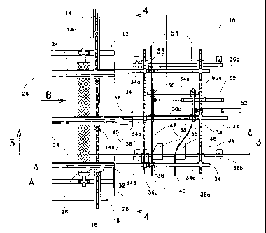
As best seen in Figure 1, a support frame constructed of various vertical and
horizontal structural supports 12 supports a plurality of lugged transfer
chains 14. Transfer chains
14 are driven, at their upstream end, on transfer chain sprockets 16. Drive
sprockets 16 are
mounted on transfer chain drive shaft 18. Transfer chains 14 are mounted at
their downstream end
on transfer chain idler sprockets 20. Idler sprockets 20 are mounted on
transfer chain idler shaft
22. Transfer chains 14 transfer boards 24 on lugs 14a over ending rolls 26
longitudinally, relative
to the transfer chains, in direction A. The boards lie laterally across the
transfer chains. Ending
rolls 26 rotate so as to urge boards 24 laterally in direction B.
The circulating paddle positioning fence 10 best seen in the remaining Figures
2-5,
is positioned just out side of lugged transfer chains 14, that is, mounted
laterally offset from the
transfer chains. Ending fence 28 is positioned generally so as to be
longitudinally aligned with
lumberline 30. Boards 24 are ended against ending fence 28. Ending fence 28 is
adjacently
l0
CA 02236508 1998-OS-O1
upstream to positioning fence 10. Ending fence 28 may be a short vertically
planar elongate plate
member. A plurality of circulating positioning paddles 32 cooperate with
ending fence 28 to take
over the ending of boards 24 from ending fence 28 as boards 24 are translated
downstream in
direction A. Paddles 32 may be planar members such as rigid plates rigidly
mounted perpendicu-
larly onto the ends of shafts 34, that is, the ends of the shafts closest to
the transfer chains. Shafts
34 are slidably mounted to a pair of parallel circulating chains 36 journalled
through bushings 34a.
As best seen in Figures 4 circulating chains 36 run on sprockets 36a.
Sprockets 36a are mounted
on shafts 36b.
Each shaft 34 has a pair of followers 38 mounted in side-by-side relation
along the
shaft. Followers 38 may be rollers. One of the rollers may be resilient to
allow rolling passage
past uneven joints, for example in the transistion from the flexible track 42
to the trolley 50.
Followers 38 are spaced apart along shaft 34 so as to snugly accept
therebetween a flexible track
42. Followers 38 are mounted on each shaft 34 on a side of each shaft 34 so as
to be radially
inwardly disposed on circulating chains 36 as shafts 34 are circulated on
circulating chains 36.
As shafts 34 are circulated in direction C on circulating chains 36, followers
38 first follow along
fixed tracks 40, then followers 38 follow flexible tracks 42. The flexible
tracks 42 are mounted
to the fixed tracks 40. The fixed tracks 40 are mounted to coincide so that
the followers 38 on the
shafts 34 and the paddles 32 move to meet and pick up the boards from the
ending fence 28 at the
lumberline 30. Shafts 34 are extended, which may be to their maximum travel,
to reach
lumberline 30 adjacent the downstream end of ending fence 28.
As better seen in the enlarged view of Figure 2a, the track along which
followers
38 run has flexible track 42 bounded on the upstream and downstream ends by
fixed tracks 40 and
54 respectively. To help ensure that the end of boards 24 maintain contact
with paddles 32, as
boards 24 are urged by ending rolls 26 concurrently towards trimmer 44 and
laterally towards
paddles 32, flexible track 42 forms a parabolic-like or other shaped curve
that helps boards 24
follow a corresponding path 45 along which paddles 32 are moving. To help in
forming the shape
11
CA 02236508 1998-OS-O1
of the curve flexible track 42 takes as it is positioned, fixed shape rigid
curved forms 46 may be
mounted laterally behind flexible track 42, adjacent where flexible track 42
is mounted to fixed
track 40.
The downstream end of flexible track 42 is mounted to lineal actuated trolley
50.
Trolley 50 is actuated by linear cylinder 52 to selectively adjust the lateral
position of trolley 50.
Trolleys 50 are guided along their lateral translation by rods SOa.
Paddles 32, on shafts 34, are translated along flexible tracks 42, that is,
the
downstream end, on to rigid tracks 54. Rigid tracks 54 are mounted to trolleys
50 at the outfeed
end that of positioning paddle apparatus 10. Followers 38 follow rigid tracks
54 so that paddles
32 hold their set position as boards 24 are translated off the ending rolls 26
and clear of paddles
32.
In a preferred embodiment paddles 32 may be mounted to a slidable sleeve 56
which is slidably mounted to fixed shafts 58. Fixed shafts 58 are mounted on
circulating pair of
chains 36 so as to extend laterally therebetween. The followers 38 are then
mounted onto the
slidable sleeves 56 such as seen in Figure 5.
As will be apparent to those skilled in the art in the light of the foregoing
disclosure, many alterations and modifications are possible in the practice of
this invention
without departing from the spirit or scope thereof. Accordingly, the scope of
the invention is to
be construed in accordance with the substance defined by the following claims.
12