Language selection

Search

Patent 2236746 Summary

Third-party information liability

Some of the information on this Web page has been provided by external sources. The Government of Canada is not responsible for the accuracy, reliability or currency of the information supplied by external sources. Users wishing to rely upon this information should consult directly with the source of the information. Content provided by external sources is not subject to official languages, privacy and accessibility requirements.

Claims and Abstract availability

Any discrepancies in the text and image of the Claims and Abstract are due to differing posting times. Text of the Claims and Abstract are posted:

  • At the time the application is open to public inspection;
  • At the time of issue of the patent (grant).
(12) Patent Application: (11) CA 2236746
(54) English Title: PNEUMO-HYDRAULIC CONVERTER FOR ENERGY STORAGE
(54) French Title: CONVERTISSEUR PNEUMO-HYDRAULIQUE POUR ACCUMULER L'ENERGIE
Status: Deemed Abandoned and Beyond the Period of Reinstatement - Pending Response to Notice of Disregarded Communication
Bibliographic Data
(51) International Patent Classification (IPC):
  • F15B 1/027 (2006.01)
  • F04B 9/115 (2006.01)
  • F15B 3/00 (2006.01)
  • F28F 5/00 (2006.01)
(72) Inventors :
  • CYPHELLY, IVAN (Switzerland)
(73) Owners :
  • IVAN CYPHELLY
(71) Applicants :
  • IVAN CYPHELLY (Switzerland)
(74) Agent: MARKS & CLERK
(74) Associate agent:
(45) Issued:
(86) PCT Filing Date: 1996-11-01
(87) Open to Public Inspection: 1997-05-15
Examination requested: 2001-09-07
Availability of licence: N/A
Dedicated to the Public: N/A
(25) Language of filing: English

Patent Cooperation Treaty (PCT): Yes
(86) PCT Filing Number: PCT/CH1996/000386
(87) International Publication Number: WO 1997017546
(85) National Entry: 1998-05-04

(30) Application Priority Data:
Application No. Country/Territory Date
3114/95 (Switzerland) 1995-11-03

Abstracts

English Abstract


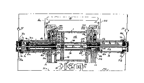
In order to maintain high efficiency close to isothermy despite high
frequencies in a pneumo-hydraulic converter with reciprocating pistons, pipe
cluster-heat exchange pipes (38) are provided in the gas working chambers of
the converter and the exchange fluid in the pipes is kept at approximately
ambient temperature. For this the gas working chambers must be arranged
axially next to one another and, in order to eliminate dead space, connected
in pairs by conical exchange valves (12a/12b) which take in the entire wall
thickness of the valve flange (5a/5b) dividing the air chambers.


French Abstract

Pour conserver de hauts rendements proches de l'isothermie malgré des fréquences de base élevées dans un convertisseur pneumo-hydraulique doté de pistons alternatifs, les tubes (38) d'un échangeur thermique à faisceau de tubes traversent les compartiments opérationnels contenant du gaz du convertisseur et le fluide d'échange passant par l'échangeur thermique (33) est maintenu approximativement à la température ambiante. Pour ce faire, les compartiments opérationnels contenant du gaz doivent être axialement juxtaposés et raccordés par paires au moyen de soupapes d'échange coniques (12a/212b) pour éviter un espace mort, lesdites soupapes occupant toute l'épaisseur de la paroi du rebord de soupape (5a/5b) séparant les compartiments renfermant de l'air.

Claims

Note: Claims are shown in the official language in which they were submitted.


CLAIMS (modified)
1. Pneumo-hydraulic converter for the conversion of pneumatic
work into hydraulic work and/or hydraulic work into pneumatic
work, with at least one reciprocating piston (2, 4a, 4b), at
least one gas working chamber (10a, 10b; 11a, 11b), which is
partially defined by the piston (2, 4a, 4b) and in which is
provided a gaseous working medium, and at least one oil working
chamber (9a, 9b), which is partially defined by a piston (4a,
4b) and in which is provided a liquid working medium, the gas
working chamber (10a, 10b; 11a, 11b) being connected to an air
storage (14) by means of valves (15a, 15b), and the oil working
chamber (9a, 9b) being connected to a hydraulic circuit,
characterized in that a tubular heat exchanger (35a, 35b, 38)
passing through the piston (2, 4a, 4b) is connected to an
exterior cooling circuit, which is designed to maintain the
temperature of the gaseous working medium at an essentially
constant level.
2. Pneumo-hydraulic converter as claimed in Claim 1,
characterized in that the tubular heat exchanger (35a, 35b, 38)
passes through the gas working chambers (10a, 10b; 11a, 11b)
and the oil working chambers (9a, 9b).

2
3. Pneumo-hydraulic converter as claimed in any of Claims 1
or 2, characterized in that the tubular heat exchanger (35a,
35b, 38) is rigidly connected to the piston (2).
4. Pneumo-hydraulic converter as claimed in any of Claims 1
to 3, characterized in that there are provided at least one
high-pressure piston (4a, 4b) and at least one pre-pressure
piston (2) with larger diameter.
5. Pneumo-hydraulic converter as claimed in any of Claims 1
to 4, characterized in that two high-pressure pistons (4a, 4b)
and one pre-pressure piston (2) are provided, which are rigidly
connected to one another.
6. Pneumo-hydraulic converter as claimed in any of Claims 4
or 5, characterized in that at least one high-pressure piston
(4a, 4b) is positioned between an oil working chamber (9a, 9b)
and a gas high-pressure chamber (10a, 10b).
7. Pneumo-hydraulic converter as claimed in any of Claims 4
to 6, characterized in that the pre-pressure piston (2) is
positioned between two gas pre-pressure chambers (11a, 11b).
8. Pneumo-hydraulic converter as claimed in any of Claims 1
to 7, characterized in that in order to prevent dead volumes
each gas high-pressure chamber (10a, 10b) is connected to a

corresponding pre-pressure chamber (11a, 11b) via a conical
seat valve (12a, 12b), which is guided on a tubular rod (8) or
the exchange pipes (38), and which occupies the entire wall
thickness of the valve flange (5a, 5b) separating the air
chambers.
9. Pneumo-hydraulic converter as claimed in any of Claims 1
to 8, characterized in that a proximity switch is provided for
control of the valves (12a, 12b, 13a, 13b, 15a, 15b, 28).

Description

Note: Descriptions are shown in the official language in which they were submitted.


CA 02236746 1998-0~-04
PNEUMO-~YDRAULIC CON~ ~ FOR FN~y STORAGE
A pneumG-hydraulic converter with reciprocating double piston
is known, which connects a compressed air storage and a
hydraulic circuit at maximum efficiency, in such a way that
energy can flow into the storage (charging) or can be removed
from the storage (discharging).
The good efficiency of isothermal processes is obtained in the
above system by stabilizing the temperature in the working
shambers ~piston spaces) during each stroke by means of the
operating medium, i.e. oil. This will result in relatively slow
working processes, since the limited velocity of the heat
transfer from the lateral surface of the cylinder to the air
during the working stroke cannot compensate the temperature
fluctuations at increased cycle frequency. As a consequence,
the structual units employed are comparatively large in
relation to the power involved.
It is the object of this invention to achieve good efficiency
while increasing the cycle frequency at the same time.
According to the invention this object is achieved by the
characteristics cited in Claim 1, wherein tubular heat
exchangers pass through some of the working chambers of the

CA 02236746 1998-05-04
_on~e~ter, and an exterior circuit maintains the exchange fluii
approximately at ambient temperature.
This heat exchanger may either be carried along by the set -f
reciprocating pistons, or remain stationary. Since the hea
exchanger moving along with the pistons will require fewer
sl~dina sealinqs ~apprGximatelv by one third), and the bun~'e
~f tubes will considerably increase the buckling and deflsct _n
strength of the piston set, the present description will be
restr cted to presenting the converter with movable heat
ex~h5nger. To achieve the desired increase in cycle frequenc-;,
5r arranaGment of working chambers is called for which invo TTes
a dramatic reduction of dead voiumes and will hence generate
nigh buckiing forces. As a consequence, buckiing strength wi-ll
be_Jme 5n extrem~ly important structural factor which must als~
be _llor.~ed fGr when deciding on the arrangemGnt of the val-,es.
As ~he converter is designed to operate as both compressor ~ni
dec~mprecsor, the valve sets on each side - each consisting o_
hish-prGssurG valve, exchange valve, low-pressure valve - ml~st
be su~ject to forced ccntrol; under certain conditions i_ -s
pcss~-le to pair off the movements of exchange valve and l_w-
pre-cure val-Te. The configuration of these valves must fl'lfill
the t poloqical requirements of t.he heat exchanger as well as
the stri-t demand for the smallest p~.s ible dead volumes. The

CA 02236746 1998-0~-04
solution of these tasks and the operation of the device
proposed by this invention will now be explained by means of
the accompanying drawings, in which
~IG. 1 is a longitudinal section through the axis of the
four cylindrical working chambers,
~IG. ~ is a section transversely to the axis in Fig. 1,
through the high-pressure chamber and through the
tube bundle of the heat exchanger,
~IG. 3 illustrates the same section as Fig. 2, though with a
bridge across the tubes of the bundle.
In its high-pressure variant the converter comprises three
coaxial and approximately equal lengths of cylindrical pipe,
the pre-pressure pipe 1, which contains the pre-pressure piston
2, having a significantly larger diameter than the two high-
pressure chamber pipes 3a, 3b, which are symmetrically arranged
vis-a-vis the pre-pressure pipe 1 and contain the equally
svmmetrical high-pressure pistons 4a, 4b. Since both movable
and stationary parts are mirror-symmetrical relative to the
longitudinal centre plane, the pre-pressure pipe 1 is connected
via valve flanges 5a, 5b to the two screwed-in high-pressure
chamber pipes 3a, 3b, which are closed off on the other ends by
fitting covers 7a, 7b fastened by screw caps 6a, 6b. Axiall~
sliding in the cylindrical pipes are a set of three pistons,

CA 02236746 1998-05-04
~ ich are riqidly conllected by the tubular rod 8 and will t:~us
der-"e 2 x 3 working chambers, i.e., oil chambers qa, a~
bet~een ccvers 7a, 7b and high-pressure pistc~ns 4a, lb; -ir
hith-pres~ure cham~ers 10a, 10b between high-pressllrG pistcn_
~a, 4b nd valve flanges 5a, 5b; and ai~ pre-pres~ure chamb_rc
lla, llb between valve flanges 5a, 5b and pre-pressure pist n
2. ~7~.e alr hi~h-pr-ss;lre chambers lûa, 10b are c~nnecte~ t~ t~le
--7- pre-pressure chambers lla, llb via the exchange valvcs i2a,
i2k; cGmmunication between the pre-pressure cham~ers lla, lib
and the exterior is established via the low-pressure va;--es
13G~ 13b; air fr~m the air stGrage 1~ i_ admitted int, th-- air
hi~h-F7~-ssure chambers 10a, 10~ via the nigh-~ressure val- _
i5a, 15b, which are supplied from t~e air storage 1~ -~ia leei
~ in-s 16a~ 16b and fittings 17a, 17b.
Ore --r'~nt ~f hydraulic pilot contrcl is shown empl~-ng -he
h ~h-~7-essure valves 15a, 15b in Fig. 1, where the pressure
-nGI~ers 18a, 18b are either depressu7~ed or pressure~i 5\;
ele~ c two-way pilot valves 20a, 2nb connected to a pressure
sc1~r-e 1~, such that the val~Je piStOIlS 21a, 2ib are set intG
mc~i n, -~r,ich are c~,nnected to the hi~ -pressl~re -.Tal7-es i5G, -
~v-a r ds 22a, 22b and nuts 23a, 23k. _~imilar de-~ices ma~r ~e
~r--~-iei ~er the exchange valves 12a, 12b and the lc~w-presslire
-~al--e 3a, 13b, wh(~se actuatin~ reds ~la, 2~b and 25a, ~5b ~r'e
S . I _~ . i l J r~

CA 022367g6 1998-0~-04
For better understanding of the functional principle of the
convertGr, a possible ~orking environment for the converter is
included in Fig. 1, beginning at the oil fittings 26a, 26k,
with feed lines 27a, 27b leading to a four-way valve 28 acting
on a variable h~y-drostatlc unit 29 with fl~wheel 30 and
electromotor~qerlerator 31. The exchange circuit begins at the
feed pump 32, which delivers the exchange fluid through the
external exchanger 33 via fitting 34b in cover 7b and via
fee~er pipe 35b to the tubular rod 8. As the tubular rod a is
stopped by a conical plllg 36 in the plane of the pre-pressure
~iston 2, the exchange fluid is pushed back through the annular
space between feeder pipe 35b and tubular rod 8 towards the
high-pressure piston 4a, where the fluid is delivered to the
bundle of heat exchange pipes 38 ~and thus to the piston 4a
its-lf) via radial bores 37b, and where the tubular rod ~ is
reached in turn via radial bores 37a; the loop back to the feed
pump 32 i3 closed via feeder pipe 35a and fitting 34a.
Like the high-pressure piston sliding sealings 39a, 39b and the
exchanae valve sliding sealings 40a, 40b, the exchanger
sealinas 41a, 41b and 42a, 42b are subject to the full pressure
~ifferencG throughout the entire period of piston movement.
This is the actual technslogical challenge of the design, in
particular if the configuration of the tube bundle incllldes a

CA 02236746 1998-05-04
bridae d~ as shGwn in Fig. 3, in crder to increase buckl na
s~l-ength ard improve heat transfer. It is Gnl~ the sliding
se-ling 44 of the pre-pressure piSt_!l 2 that is not expcsed t_
thle high pressures, as it is Jnly sukject to the prG-pLcs~li~e.
The remaining sealings, which are not referred to in detai ,
are i,ni~ subject to statis pressures or short-stroke movements.
The functional principle of the converter will now be dis(-u-s
with reference to a de~ompression ~dischargei cic_e
c rr_sp~_nding to the position of val--es shown here, ~here the
p-stons m~Te towards the right: at the moment shown ir. the
~rawing the air high-pressure chamber lOb is ~irectly ccnnected
t,~ the air storage 14 through the open air hiah-pressure valve
'5k. The pressure force acts on the oi chamber 9b and is
t~ar-mittGd via the oil column in line ~7b and the four--~a~-
.-a~ to the prGssure side fjf the hydrcstatic unit 29 actir-
~as ~ motor, which in turn will actuate the f ywheel 3û and ~he
~erieratGr 31. Moreover, ~lle to th s mGvement tG the r ~
dGc_mpressed air in chamber llb is pushed out into the open by
the ~re-pressure piston 2 through the open low-pressure -~alv~
~ ; at the same time the air from the previous mGvement rhrhi h
has remained un(ier pre-pre_sure in the high-pressure chambe1-
~, will assume discharge pressure -,-ia the cpen exchange -Ta I -~.-e
1~ iue t the expanding pre-pressur-- chamber lla. B~ the cam~-
movGment the oil emeraing f~sim the hvdros~atic lln t is fcLc-d

CA 02236746 1998-0~-04
into the oil chamber 9a. The force picked up by the cushion in
the oii chamber 9b is thus generated not only by the exposure
to high pressure in the air high-pressure chamber lOb, but also
by the thrust produced by the pre-pressure at the large surface
of the pre-pressure piston 2, which is transmitted via the
tubular rod 8 and pipes 38 of the tube bundle. This is the very
site where the danger of buckling is encountered. At a certain
moment Gf this movement to the right, which is to be determined
by computer, the high-pressure valve 15b must be closed, for
the decompression of the thus defined volume to yield at the
end sf the stroke precisely that pre-pressure which will
produce the discharge pressure due to expansion after the
beginnina of reverse movement, by pushing the volume of the air
high-pressure chamber lOb into the pre-pressure chamber llb. At
the beginning of the reverse movement, 15a, 13a and 12b must be
opened ~nd 12a and 13b must be closed simultaneously with the
switchover of 28 (13b being forced into closing position by the
oncoming pre-pressure piston 2). The switchover may be
initiated by a proximity switch.
It should be emphasized here that the specific topological
configuration is part of the invention and is particularly well
suited for the repetitive thermodynamic process described; the
special arrangement of pressure chambers and exchanger will

CA 02236746 1998-05-04
permir the shuttle valve design avoiding dead volumes, which is
essentiai to the principle of maximum efficiency conversicn.
It should be pointed out finally that the pressure of the oil
penelrating from the converter during e2ch stroke is subjecr to
variations at a ratio of about 1:30 (at 200 bar in the air
storaaG ~0), which will be an obstacle tG the direct use sf the
con~erter in many applications, as the hydrostatic units have a
displacement volume control range of 1:10 at most. If the
converter is to operate at constant power the addition of a
flywheGl is recommended, which can bridge a wide range of cycle
frequencics; the hydrostatic unit would only have to folloN
effective changes in load in that case.
I- the converter is employed exclusively as a compressor, the
fGrced control of the valves ma~ be omitted, but the fcur-way
switchover valve ~8 must be synchronized with the stroke of the
cGnverter, either automatically (by the pressure peak at the
st-p; or by means of a proximity switch. In the instance o
simple compression tasks (e.g. for sosling circuits) the
compressoL need not include a pre-pressure cvlinder; the
tubu~ar heat exchanger may be ch,sen to b- either stationary or
mc-.!able ~n this case, as no bucklinq forces will arise.

Representative Drawing
A single figure which represents the drawing illustrating the invention.
Administrative Status

2024-08-01:As part of the Next Generation Patents (NGP) transition, the Canadian Patents Database (CPD) now contains a more detailed Event History, which replicates the Event Log of our new back-office solution.

Please note that "Inactive:" events refers to events no longer in use in our new back-office solution.

For a clearer understanding of the status of the application/patent presented on this page, the site Disclaimer , as well as the definitions for Patent , Event History , Maintenance Fee  and Payment History  should be consulted.

Event History

Description Date
Inactive: IPC from MCD 2006-03-12
Application Not Reinstated by Deadline 2003-11-03
Time Limit for Reversal Expired 2003-11-03
Deemed Abandoned - Failure to Respond to Maintenance Fee Notice 2002-11-01
Amendment Received - Voluntary Amendment 2002-02-18
Letter Sent 2001-09-27
Inactive: Entity size changed 2001-09-20
All Requirements for Examination Determined Compliant 2001-09-07
Request for Examination Requirements Determined Compliant 2001-09-07
Request for Examination Received 2001-09-07
Inactive: Notice - National entry - No RFE 1998-10-02
Amendment Received - Voluntary Amendment 1998-09-17
Filing Requirements Determined Compliant 1998-08-20
Inactive: Filing certificate correction 1998-08-20
Inactive: IPC assigned 1998-08-04
Inactive: First IPC assigned 1998-08-04
Inactive: IPC assigned 1998-08-04
Classification Modified 1998-08-04
Inactive: Notice - National entry - No RFE 1998-07-17
Application Received - PCT 1998-07-16
Application Published (Open to Public Inspection) 1997-05-15

Abandonment History

Abandonment Date Reason Reinstatement Date
2002-11-01

Maintenance Fee

The last payment was received on 2001-11-01

Note : If the full payment has not been received on or before the date indicated, a further fee may be required which may be one of the following

  • the reinstatement fee;
  • the late payment fee; or
  • additional fee to reverse deemed expiry.

Please refer to the CIPO Patent Fees web page to see all current fee amounts.

Fee History

Fee Type Anniversary Year Due Date Paid Date
Basic national fee - standard 1998-05-04
MF (application, 2nd anniv.) - standard 02 1998-11-02 1998-10-15
MF (application, 3rd anniv.) - standard 03 1999-11-01 1999-10-21
MF (application, 4th anniv.) - standard 04 2000-11-01 2000-10-19
Request for examination - small 2001-09-07
MF (application, 5th anniv.) - small 05 2001-11-01 2001-11-01
Owners on Record

Note: Records showing the ownership history in alphabetical order.

Current Owners on Record
IVAN CYPHELLY
Past Owners on Record
None
Past Owners that do not appear in the "Owners on Record" listing will appear in other documentation within the application.
Documents

To view selected files, please enter reCAPTCHA code :


To view images, click a link in the Document Description column. To download the documents, select one or more checkboxes in the first column and then click the "Download Selected in PDF format (Zip Archive)" or the "Download Selected as Single PDF" button.

List of published and non-published patent-specific documents on the CPD .

If you have any difficulty accessing content, you can call the Client Service Centre at 1-866-997-1936 or send them an e-mail at CIPO Client Service Centre.


Document
Description 
Date
(yyyy-mm-dd) 
Number of pages   Size of Image (KB) 
Representative drawing 1998-08-14 1 26
Claims 1998-05-04 3 71
Drawings 1998-05-04 2 61
Cover Page 1998-08-14 1 65
Abstract 1998-05-04 1 17
Description 1998-05-04 8 285
Claims 1998-09-17 2 65
Reminder of maintenance fee due 1998-07-20 1 115
Notice of National Entry 1998-07-17 1 209
Notice of National Entry 1998-10-02 1 192
Reminder - Request for Examination 2001-07-04 1 118
Acknowledgement of Request for Examination 2001-09-27 1 194
Courtesy - Abandonment Letter (Maintenance Fee) 2002-12-02 1 176
Correspondence 1998-08-20 1 26
PCT 1998-06-02 6 159
PCT 1998-05-04 19 608
Correspondence 2001-09-07 1 38