Note: Descriptions are shown in the official language in which they were submitted.
CA 02236854 1998-OS-06
WO 97132804 PCT/Td'97/00047
REWINDER INCORPORATING A TAIL SEALER
DESCRIPTION
Technical field
The present invention relates to an automatic surface rewinder
for the
formation of rolls or logs of web material. Rewinders of
this type are
commonly used for the production of rolls or logs of paper
which are
io subsequently cut to produce smaller rolls of toilet paper,
kitchen towels and
similar.
Back4round art
There are many known types of rewinders, based on the principle
of
surface winding, for the production of rolls or logs of web
material. Some
~s examples of these automatic surface rewinders (in other words,
those in
which the logs are formed automatically in rapid succession
and the log in
formation is rotated by contact with an external system of
belts or rollers) are
described in US-A-4,723,724, US-A-4,856,725, US-A-4,828,195,
US-A-
4,962,897, US A-4,487,377, US-A-4,931,130, US-A-5,137,225,
2o US-A-5,248,106, US A-5,368,252, GB-A-2.105.688, WO-A-9421545.
Some of these rewinders, for example those described in EP-A-0
580
561 and EP-A-0 611 723 also produce logs without central
winding cores.
These rewinders produce a high number of rolls per unit of
time, and
these are subsequently discharged to the exterior of the
rewinder and are
2s collected in a sorter or in an intermediate storage receiver.
Before it is
possible to proceed to the cutting of each log into smaller
rolls and the
subsequent packaging, it is necessary to glue the free tail
edge of the web
material wound on each log to prevent the unwinding of the
end portion from
causing problems in the subsequent phases, particularly in
the packaging.
so For this purpose, the logs discharged from the rewinder and
collected
in the accumulators or sorters following the machine are
conveyed
individually to a separate and subsequent section of the
"converting" line in
' which one or more machines are provided for the gluing of
the free tail edge
of the material of each roll, these machines being commonly
called tail
3s sealers.
Examples of tail sealers are described in US-A-3,044,532,
US-A-
4, 475, 974, U S-A-4, 963, 223, U S-A-5, 242, 525, E P-B-0
481 929, WO-A-
9515903, WO-A-9515902.
CA 02236854 1998-OS-06
WO 97/32804 PCT/IT97/00047
- 2 -
All the tail sealers have a station in which the free tail edge of the web
material is unwound and positioned before the adhesive is applied.
The necessity of having a rewinder, an intermediate accumulator or
sorter and a tail sealer (which in turn comprises a station for the unwinding
s and positioning of the free tail edge to be glued and a gluing station),
causes
the line to have large overall dimensions and makes it necessary to
synchronize the different sections of the fine with each other, resulting in
high
costs in respect of programming and control systems. These costs are
accepted in plants with high output, of the order of more than 9-10 logs per
io minute, but cannot always be borne with lower outputs.
Disclosure of invention
The present invention is based on the idea of combining the winding
and gluing of the free tail edge of the fog in a single section of the
processing
line, thus eliminating not only the intermediate accumulator or receiver, but
Is also the station for the unwinding and positioning of the free tail edge of
the
fog.
Essentially, according to the invention, the log is caused to be
discharged as soon as it is formed from the winding cradle of the rewinder,
with the tail edge unwound, directly onto a discharge surface along which the
.
2o adhesive is applied to the roll to close the free tai! edge during the
rolling of
the fog on the discharge surface. The length of the free edge and the position
of the adhesive on the roll are selected in such a way that as it is rewound
the
edge covers the line of adhesive and extends beyond it by a few millimetres,
forming a tab that can be picked up. In this way the dimensions of the
2s processing line are reduced drastically and also the programming and
operation of the line are considerably simplified.
In practice, the method of winding according to the invention may
comprise the phases of:
- feeding the said web material to surface winding means;
30 - winding a predetermined quantity of the said web material onto a roll;
- dividing the web material;
- discharging the roll formed by the said surface winding means, with a
free tail edge of the said web material unwound from it, onto a '
discharge surface along which the said adhesive is applied to the
ss cylindrical surface of the roll;
- starting the winding of a new roll while the previously formed roll is
discharged and glued.
The surface winding may be carried out by one of the conventional
CA 02236854 1998-OS-06
WO 97/32804 PG'T%/IT~T/0004T
- 3 -
systems known at the present time. Preferably, the winding system which is
used will comprise at least two winding rollers rotating in the same direction
and forming between them a nip through which the web material to be wound
passes. After the nip there is provided a winding area which is preferably
s formed by a third winding roller which is movable to permit and control the
increase of the diameter of the log. If this winding system is adopted, at the
end of the winding the web material is severed before the said winding cradle
and the second winding roller is stopped to cause the completed roll to roll
on
it and to cause it to be discharged from the said winding cradle. By stopping.
io the second winding roller, the roll can be discharged with a free edge of
web
material sufficiently long to allow convenient gluing, as will be shown more
clearly by the following detailed description.
To improve the control of the phase of discharge of the log from the
winding cradle, in this case it is advantageous to have the said first winding
Is roller slowed down temporarily at the end of the winding, together with the
rest of the machine, including the means of feeding the web material.
in practice, the adhesive is delivered from a delivery slit provided along
the discharge surface and extending parallel to the axis of the roll.
The surface rewinding machine according to the invention comprises
2o winding means forming a surface winding unit for the formation of the said
rolls; before the said winding unit, means of dividing the web material which,
at the end of the winding of a roll, sever the web material, thus generating a
free tall edge of the web material wound onto the said roll and a free leading
edge of web material for starting the winding of a subsequent roll; and a
2s discharge surface after the said winding unit, onto which the formed rolls
are
discharged at the end of the winding. Delivery means are also disposed along
the said discharge surface to deliver an adhesive to each of the said rolls
when they roll on the said discharge surface, in order ,to glue the free tail
edge of the web material wound on the roll, which is discharged by the
3o winding unit onto the said discharge surface with the said free tail edge
partially unwound.
In practice, the discharge surface has an adhesive delivery slit
extending parallel to the axis of the roll. The log collects the adhesive from
the slit as it rolls over it.
3s To obtain correct gluing of the free tail edge when the log rolls on the
discharge surface, it is useful for the web material to be severed at the end
of
the winding in such a way that a sufficiently long free tail edge is left
unwound
from the log. This may be achieved, for example, by providing before the nip
CA 02236854 1998-OS-06
WO 97/32804 PCT/IT97/00047
formed by the winding rollers a rolling surface forming with the surface of
tf~e
said first winding roller a channel within which the winding of each rol(
starts.
The web material is severed in the proximity of the entrance of the channel.
The severance of the web material may take place in various ways,
s depending among other considerations on whether the winding takes place
with or without a central tubular core. Some examples of means of dividing
the web material are described below.
Brief description of the drawings
The invention will be more clearly understood from the description and
io the attached drawing, which shows a practical and non-restrictive example
of
the invention. fn the drawing,
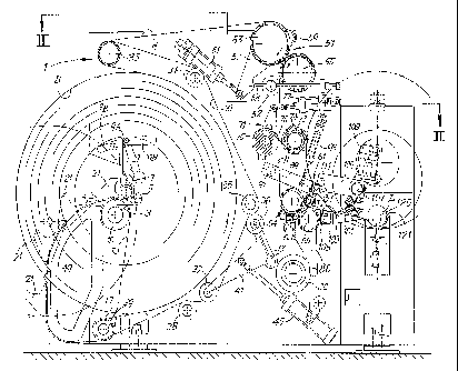
Fig. 1 is a side view, in partial section, of the processing line;
Fig. 2 is a plan view through II-II in Fig. 1;
Fig. 2A is an enlarged detail through IIA-IIA in Fig. 2;
is Fig. 3 is an enlargement of the winding area;
Figs 4A-4D show successive phases of the winding and gluing of the
free tail edge of a log:
Figs 5A-5D show schematically, in four successive instants of the
operating cycle, a solution in which winding cores are used; ,
2o Fig. 6 shows schematically a further embodiment of the invention with
a winding core; and .
Figs 7 and 8 show a different embodiment in various phases of the
operation.
Detailed description of the invention
2s The application of the invention to a compact processing line, in which
the reel unwinding devices and the cutter which cuts the logs into smaller
rolls
are also present, is illustrated in the following description, and
particularly
with reference to Figs 1 to 4. This is intended to show how it is possible, by
using the method and rewinder according to the present invention, to produce
so a line whose size is such that it can be entirely contained in a transport
container. However, it should be understood that the inventive concept may
also be applied to fines of different structure and configuration, for example
in
lines for the production of industrial rolls, in other words those of greater
diameter.
3s .With reference to Figs 1 to 3, the processing line, indicated in a
general way by the number 1, comprises an unwinding station in which a reel
of large diameter, indicated by B, of web material N is unwound so that it can
then be rewound info logs or rolls whose diameter is equal to the diameter of
CA 02236854 1998-OS-06
WO 97!32804 PCT1IZ'97J00047
_ cJ _
the product intended for the end user. The reel B, with a central supporting
axle A, is supported at both ends by a corresponding pair of idle support
rollers 3, 5, and is held in this position by a third upper roller 7 supported
by a
bracket 9. The bracket 9 is hinged at 9A and has a counterweight 9B which in
s turn is hinged at 9A and oscillates with respect to the bracket 9. The
counterweight 9B, in the angular position shown in Fig. 1, presses the bracket
against a fixed stop 11. The stop is in such a position that when the bracket
9
presses against it the roller 7 is in such a position as to hold the core A of
the
reel B in the correct unwinding position.
io The reel B is brought into this position by means of a pair of
continuous parallel chains 13 which are located on the two sides of the
machine, run around toothed wheels 15 and 17 and are guided by a
corresponding curved guide 19. Each of the continuous chains 13 carries a
support 21 designed to receive the corresponding end of the axle A inserted
is into the core of the reel B.
The two supports 21 and the guides 19 are shaped in such a way that
they gently discharge the support axle A of the reel B onto the cradle formed
by the support rollers 3 and 5, this operation being permitted by the
anticlockwise oscillation of the bracket 9 which carries the third roller 7.
When
2o the axle A of the reel B has been positioned at the lowest possible point
between the rollers 3 and 5, the roller 7 is returned by the action of the
counterweight 9B to the position shown in Fig. 1, thus avoiding the risk of
the
reef B moving backwards. A forward fall is conveniently prevented by the fact
that the roller 5 is disposed at a point higher than the roller 3. The core of
the
2s empty reel and the corresponding support axle A are then discharged from
the seat 3, 5 by means of the said supports 21 which are made to move
backwards by the chains 13. This movement is possible after the axle A has
been released by a manual movement of the counterweight 9B to the position
indicated in broken lines in Fig. 1. This causes a sufficient anticlockwise
so oscillation of the bracket 9 and of the roller 7 to release the axle A.
The reel B is unwound by means of a set of flat unwinding belts 31
which are parallel to each other, only one of which is visible in the drawing,
the others being disposed parallel to it. The unwinding belt 31 is run around
a
powered cylinder 33 and a set of pulleys 34, 35, 36, 37, 38, 39. The return
3s pulleys 36 and 37 are mounted on a bracket 41 pivoted at 43 on the
corresponding side member of the machine and connected to a cylinder and
piston actuator 45. With this disposition, the tension on the unwinding belt
31
is maintained when the diameter of the reel B varies.
CA 02236854 2004-11-25
-6-
The web material N, which is unwound from the reel as a result of the
movement of the unwinding belts 31 and the friction between these and the
external surface of the reel B, is run around the return cylinder 33 round
which the belts 31 run, and passes through an embossing unit 51 comprising
a pair of embossing cylinders 53, 55. The cylinder 53 is supported by a pair
of brackets 57 (only one of which is visible in Fig. 1) pivoted at 59 on the
corresponding side member and pressed by a pneumatic actuator 61 against
an adjustable stop 63. In the illustrated example, the embossing cylinder 55
has a fixed axle. The embossing unit 51 may be omitted, in which case the
web material N runs around a roller 52 indicated in broken lines in Fig. 1.
The web material N (whether embossed or not) then passes through a
perforator unit 71, of a known type, which in the example shown in the
drawing has a rotating perforating roller 73 with a plurality of blades 74
interacting with a fixed blade 76 carried by a non-rotating roller or beam 75,
whose position can be adjusted by an actuator 77. The blades 74 or the
blade 76 are serrated. In a known way, the perforator 71 makes a set of
equidistant perforation lines on the web material N which, when processed in
this way, is sent to a rewinding unit, indicated in a general way by the
number 81.
The rewinding unit 81 comprises three winding rollers 83, 85 and 87,
which are subsequently indicated as the first, second and third winding roller
respectively, and which rotate in the same direction (anticlockwise in the
example). The web material is run around the first winding roller 83 and is
wound to form a log L which, in the intermediate processing phase shown in
Fig. 1, comes into contact with the three rollers 83, 85, 87. The winding
takes place in a known way and will not be described in great detail here,
since reference may be made, for example, to the European Patent
Application published under number EP-B-0 580 561. At this point it is
sufficient to note that the increase of the diameter of the log L is permitted
by the oscillation of the arm 89, which supports the third winding roller 87,
about its pivot 91. The oscillation is controlled by the actuator 93 which can
be of any kind and is shown purely for convenience in the form of a cylinder
and piston actuator. The roller 87 may also be raised by the growth of the
log being formed. Additionally, the winding of the initial core of the
log takes place between the first winding roller 83 and a curved
rolling surface 84 carried by an oscillating unit 86 pivoted about the axis of
the second winding roller 85. The oscillation of the unit 86 and consequently
of the curved rolling surface 84 is caused by a cam 88 or other suitable
system. As will be described in greater detail in the following text and
CA 02236854 1998-OS-06
WO 97/32804 PCT/IT97/000~7
7 _
as is moreover already known from EP-A-0 580 561 t;.at the end of the winding
of a log the oscillating unit 86 oscillates in the clockwise direction and the
rolling surtace 84 is brought into contact with the upper roller 83. In this
way
the web material is gripped between the rolling surface 84 and the roller 83,
and breaks, and the free leading edge thus created starts to wind onto itself
between the roller 83 and the rolling surtace 84, advancing towards the nip
formed between the roller 83 and the roller 85 to complete the winding of the
new log between the three rollers 83, 85, 87. In this way a log L without a
central tubular core is formed.
io When the desired quantity of web material N has been wound onto the
log, or when the log has reached the desired diameter or weight, the web
material N is severed and the completed log L is discharged onto a discharge
surface 101. The precise process by which the log L is discharged at the end
of the winding will be described in the following text with reference to Figs
4A
is 4D.
The discharged log L rolls on the discharge surface 101, passing over
an adhesive delivery slit 103. The adhesive is delivered by a delivery device
indicated in a general way by the number 105 and disposed under the
discharge surface 101 so that it glues the free tail edge of the log onto the
2o external surface of the log. The adhesive delivery device 105 is not
described
in detail, since it may be made, for example, according to one of the
solutions
described in EP-B-0 481 929, US-A-5,242,525, US-A-5,259,910, WO-A-
9515903. The principal characteristic of delivery devices of this type is that
they interact with a log discharge surface, so that the gluing and the closing
2s of the tree tai! edge take place simply by rolling on the discharge surtace
101
along which the transverse adhesive delivery slit 103 is provided.
A log closing roller 107 is provided near the end of the discharge
surface 101. The position of the roller 107 is adjustable by rotation of a
support arm 109 pivoted at 111 on the structure of the machine. The roller
30 107 is rotated by a gearmotor 108 to cause the controlled rotation of,the
log,
which passes between the roller 107 and the underlying discharge surface
101, and consequently the closure of the free tail edge. The position of the
roller 107 and of its pivot 171 may be adjusted in such a way that the contact
between the log and the roller 107 takes place in the area of application of
ss the adhesive. i
The log closed in this way is discharged into a cradle 121 of ~a cutter
indicated in a general way by the number 123 {Fig. 2). In the cradle '121 the
log L is made to advance by a pusher 125 towards a cutting head co ~mprising
i
i
CA 02236854 1998-OS-06
WO 97/32804 PCT/IT97/00047
_ g _
a rotating plate 127 keyed to a driving shaft 129 which rotates it of a
substantially constant velocity. The pusher 125 is carried by a continuous
chain 126 running around two wheels, one of which is powered by a motor
128.
s The rotating plate 127 supports a shaft 131 of a circular blade 133 for
cutting the log L into rolls of the desired width. The rotation of the shaft
131
and consequently of the blade 133 is obtained by means of a pinion 135
keyed to the axle of the shaft 131 and engaging with a ring gear 137 coaxial
with the axis of the plate 127 and integral with the fixed structure of the
io machine. The rotation of the plate 127 thus also causes the circular blade
133
to rotate about its own axis. The cutter described above has a more simple,
more compact and more economical structure than that of normal cutters for
logs.
The rolls cut by the blade 133 are pushed by the pusher 125 towards a
is conveyor consisting of a pair of small belts of circular section 141, 143,
one of
which extends further than the other. The two small belts 141, 143 are driven
by a gearmotor 145 and discharge the rolls onto a conveyor which carries
them to the packaging machine or other (not shown). The difference in length
between the two belts permits the discharge of the trimmings, in other words .
20 of the two "slices" that are cut from the head and tail of the log. The
trimmings
are much narrower than the rolls and normally tilt, coming to rest on the
small
belts 141, 143 with their axis vertical. An ad)ustable smooth bar 147,
positioned at a higher point than the small belt 141, as seen in the
enlargement in Fig. 2A, is disposed after the small belt 141. The difference
in
2s height between the small belt 141 and the smooth bar 147 is such that the
tilted trimmings pass under the smooth bar 147, fall, and are collected in the
area beneath. Conversely, the rolls continue to advance, being supported on
one side on the smooth bar 147, which allows them to advance easily by
sliding, and on the other side on the small belt 143 which continues to convey
3o them towards the exit of the line 1. Should the trimming fail to tilt
before
reaching the smooth bar 147, it will tilt as soon as it comes into contact
with it,
owing to the small axial dimension od~ the trimming and the friction torque,
which cause it to lose its balance and consequently to fall into the space
between the smooth bar 147 and the small belt 143.
3s The whole line described up to this point, with the sole exception of the '
small hefts 141 and 143, the casing 140, and the guides 19 and
corresponding chains 13 if present, may be housed in a transport container,
having a length of 2200 mm, a height of 1950 mm and a width which in a(I
CA 02236854 2004-11-25
_g_
cases is less than the largest dimension of the container.
This drastic reduction in size is obtainable also as a result of certain
arrangements which are particularly useful for reducing the size of the line.
in particular, a considerable reduction in length is obtained by the
disposition
of the gait sealer for the free tail edge, and of the corresponding delivery
device 105, directly at the exit from the winding area formed by the rollers
83, 85, 87. As a matter of fact, by contrast with conventional lines, in which
the tail sealer for the free tail edge of the log has a station for unwinding
and
positioning the free tail edge for gluing, in the illustrated processing line
the
operations of positioning the free tail edge are carried out as the final
phase
of the rewinding process itself, in other words of the process which takes
place between the rollers 83, 85, 87.
The operations of discharging the completed log, gluing the free tail
edge and starting the winding of the next log are illustrated in Figs 4A-4D.
The procedures of this phase, known as the exchange phase, are as follows:
the second winding roller 85 is slowed down considerably (beyond the values
of deceleration normally used in conventional rewinders), to zero velocity if
necessary (Fig. 4A). The web material is gripped between the external
surface of the roller 83 and the rolling surface 84 which is made to oscillate
towards the roller 83. The web material N is torn along a perforation line as
a result of the gripping and the rotation of the rollers 83, 87, in a way
known
to those skilled in the art, and known in particular, for example, from the
publications cited in the present description. In particular, the break may be
achieved by making a portion of roller have a surface with a low coefficient
of friction, on which the material N is gripped and made to slide backwards
with respect to the movement of the roller, causing the break, followed by a
portion of surface with a higher coefficient of friction, as described in EP-A-
0
611 723.
In this phase the speed of the machine, and in particular the
peripheral velocity of the roller 83, are preferably reduced, with a
consequent reduction in the speed of the feed of the web material N. The
peripheral velocity of the roller 87 is also reduced proportionally, but is
always kept higher than the peripheral velocity of the roller 85. The
difference between the peripheral velocity of the roller 87 and that of the
roller 85 causes the log L to roll on the roller 85 towards the discharge
surface 101, until the log L ceases to be in contact with the roller 85 and is
discharged onto the surface 101 (Fig. 4B).
These operations are synchronized and controlled in such a way that,
when the log L starts to touch the discharge surface 101, the length of the
CA 02236854 2004-11-25
-10-
free tail edge LL unwound from it is known and selected in such a way that,
with allowance made for the subsequent rolling and consequently the
gradual rewinding of the free tail edge on the log L, the log comes into
contact with the transverse delivery slit 103 in the correct position to make
the free tail edge adhere to the log in the proximity of the terminal line.
For
this purpose, the severance of the web material is made to take place at a
sufficient distance from the log L to give a sufficient length of the unwound
free tail edge. Additionally, to prevent the free tail edge from being rewound
excessively onto the log L while the latter is rolling towards the discharge
surface 101 and towards the delivery slit 103, the roller 85 is slowed down
considerably or preferably brought to a halt.
After the log L has touched the slit 103 and has consequently picked
up the adhesive C (Fig. 4C), the rolling continues until the free tail edge LL
is
rewound completely onto the log L and covers the line of adhesive C, thus
being fixed to the log (Fig. 4D). At the same time, the speed of the machine
is returned to the operating level. The roller 85 is returned to the operating
speed over a longer period, for the reason described below. The free leading
edge created on the web material arriving from the reel B is wound onto
itself in the channel formed by the rolling surface 84 and the surface of the
roller 83, to form the central part of the new log (Fig. 4B). This initial
winding turns roll until they pass through the nip formed by the rollers 83,
85 (Figs 4C, 4D) and are inserted into the winding cradle formed by the
three rollers 83, 85, 87 (Fig. 4D) to form the next log. The passage through
the nip is caused by the difference between the peripheral velocities of the
rollers 83 and 85, which continues for the time necessary for the insertion of
the initial winding turns into the said cradle, owing to the fact that the
roller
85 returns to the operating speed over a longer period than the rollers 83,
87.
Figs 5A-5D show an embodiment in which the winding is done onto a
tubular winding core T. Identical numbers indicate parts identical or
corresponding to those described with reference to the preceding figures.
The rolling surface before the nip between the rollers 83, 85 is indicated by
84X and is mounted on a unit 86 pivoted about the axis of the second
winding roller 85. The number 88X indicates the cam causing the oscillation
of the unit 86X and consequently of the rolling surtace 84X. The distance
between the rolling surface 84X and the cylindrical surface of the roller 83
is
greater than in the preceding case. The rolling surface 84X is associated with
an elastic plate 151 which forms, together with a support 153, a holder for a
tubular winding core T. In Fig. 5A, where a log L is in the initial phase of
CA 02236854 2004-11-25
-11-
winding between the rollers 83, 85, 87, the oscillating unit 86 is in its
lowest
position. In this position a tubular core T is inserted, laterally for
example,
and guided by a fixed support surface 155 which temporarily forms -together
with the support 153- the core insertion holder. The insertion of the tubular
core T, which has previously been provided with a line of adhesive parallel to
its axis may take place in a known way, for example as described in US-
A4,931,130. While the winding of the log L continues, the unit 86 is raised
until it reaches a position in which the tubular core T is kept at a very
short
distance from the surface of the winding roller 83 and is held there by the
elastic plate 151 and the stop formed by the support 153. At the end of the
winding of the log L, the core T is brought up to the surface of the roller 83
(Fig.SB) and then pressed against it (Fig. SC) by the further oscillation of
the
unit 86. In the position shown in Fig. 5C, the web material N is gripped
between the core T and the cylindrical surface of the roller 83 with
consequent breaking of the web material N at a point intermediate between
the gripping position and the completed log L. The machine is synchronized
in such a way that in the vicinity of the core T there is a perforation line
such
that the breaking takes place at a point, close to the tubular core T and not
close to the log L, to create a sufficiently long free tail edge LL. The
breaking
is facilitated by the fact that four areas 83B with a high coefficient of
friction
(covered with abrasive cloth, for example) and, alternating with these, four
areas 83A with a low coefficient of friction (made of polished steel, for
example) are provided on the roller 83. The machine is synchronized in such
a way that the tubular core T is pressed against a polished area 83A, while
the perforation line on which the tearing takes place is located preferably in
the area of transition between the area 83A on which the core presses and
the area 83B with a high coefficient of friction adjacent to the former and
after it with respect to the direction of advance of the web material.
When the tubular core T is pressed against the roller 83, it is made to
rotate by the roller 83, and rolls along the rolling surface 84. The line of
adhesive applied previously causes the free leading edge of the web material
N to be fixed in such a way as to permit the start of the winding of a new
log. The elastic deformation of the plate 151 allows the core to leave its
holder and to roll on the rolling surface 84X.
The completed log is discharged onto the discharge surface 101 and
its free tail edge LL is . glued by the procedure described previously with
reference to Figs 4A-4D.
In an alternative solution, the core T may be free of adhesive and the
CA 02236854 1998-OS-06
WO 97/32804 PCT/IT97/00047
- 12 -
winding starts with .the aid of one or more sets of nozzles, in a known way. .
.
Fig. 6 shows a solution for winding with a tubular core, in which the
web material is broken by a member dedicated to this purpose, instead of by .
the pressure of the core. In this solution, a rolling surface 84Y, which is
fixed
s instead of oscillating, is disposed before the nip formed between the two
rollers 83, 85. This terminates in a holder 157 into which a tubular core T, ,
which may have been previously provided with a line of adhesive, is inserted
laterally. When the log L has been completed (the instant shown in Fig. 6),
the tubular core T is pushed against the roller 83 by a pusher 161 carried by
io an oscillating unit 163 pivoted at 165 on the structure of the machine and
driven by a cylinder and piston or equivalent actuator 167. The oscillating
unit
163 also carries a presser 169 which, when the core is pushed by the pusher
161 against the external surface of the roller 83, grips the web material N
between the presser 169 itself and the surface of the roller 83, causing the
rs breaking of the web material N and consequently the generation of the free
tai! edge LL to be wound and glued onto the completed log L and the free
leading edge which is fixed to the incoming tubular core T. In this case also,
the roller 83 has portions of surface 83A, 83B with low and high coefficients
of
friction respectively. The tubular core T is then made to advance by rolling
2o along the channel formed between the cylindrical surface of the roller 83
and
the rolling surface 84Y until it reaches the nip between the rollers 83 and
85.
Figs 7 and 8 show a further embodiment of the invention, in which the
logs are again formed on a tubular core. Parts identical or equivalent to
those
in Fig. 6 are indicated by the same reference numbers. In this embodiment,
as the means for dividing the web material N comprise an elastic plate or a
plurality of parallel elastic plates 181 carried by an oscillating system 183
hinged about an axis which, in the example illustrated, coincides with the
axis
of rotation of the roller 85 (but which may, obviously, be positioned
differently). The oscillation is caused by an actuator 185.
3o During the winding of a lag L, the elastic plate 181 is held in the
position indicated in broken fines in Fig. 7, while a new tubular core T is
brought into the holder 157 indicated in broken fines in Figs 7 and 8. When
the log L has been completed, the elastic plate 181 is brought info contact '
with the web material N running around the roller 83, and the tubular core T
is
3s pushed by the pusher 161 towards the entrance of the channel formed
between the surface 84Y and the roller 83 and against the latter. The further
pressure of the elastic plate 181 against the external surface of the roller
81
by means of the actuator 185 causes a flexional deformation of the plate (Fig.
CA 02236854 1998-OS-06
WO 97/32804 PCT/IT97/00047
- 13 -
8) and a .consequent backward sliding of its end with respect to the direction
of advance of the web material N. This causes the breaking of the web
material on the perforation line which is immediately after the point of
contact
of the elastic plate 181. In this case also, the roller 82 is provided with
s portions of surface 83A and 83B with low and high coefficients of friction
respectively. The elastic plate 181 touches the web material N next to a
portion of surface 83A with a low coefficient of friction, so that the web
material N can easily slide backwards as a result of the flexing of the
elastic
plate 181 and form a loop NA between the elastic plate 181 and the new
to tubular core T.
The free edge formed in this way can be applied to the new tubular
core T by means of an adhesive previously applied to the core itself or by
means of a suitable, system of nozzles which generate air blasts (not shown).
In the embodiment shown in Figs 7 and 8, the severance of the web
is material N may take place even with the roller 83 completely halted, since
the
movement caused by the flexing of the elastic plate 181 is sufficient to cause
the breaking of the web material. The solution described here therefore
enables the web material N to be broken even with the machine stopped.
It should be understood that the drawing shows only an example
2o provided solely as a practical demonstration of the invention, and that
this
invention may vary in its forms and dispositions without departure moreover
from the scope of the guiding concept of the invention. Any presence of
reference numbers in the attached claims has the purpose of facilitating the
reading of the claims with reference to the description and the drawing, and
2s does not limit the scope of protection represented by the claims.