Language selection

Search

Patent 2237024 Summary

Third-party information liability

Some of the information on this Web page has been provided by external sources. The Government of Canada is not responsible for the accuracy, reliability or currency of the information supplied by external sources. Users wishing to rely upon this information should consult directly with the source of the information. Content provided by external sources is not subject to official languages, privacy and accessibility requirements.

Claims and Abstract availability

Any discrepancies in the text and image of the Claims and Abstract are due to differing posting times. Text of the Claims and Abstract are posted:

  • At the time the application is open to public inspection;
  • At the time of issue of the patent (grant).
(12) Patent: (11) CA 2237024
(54) English Title: ACTIVE DENTAL FLOSS CONTAINER
(54) French Title: CONTENANT DE SOIE DENTAIRE POLYVALENT
Status: Expired and beyond the Period of Reversal
Bibliographic Data
Abstracts

English Abstract


A dental floss container and dispenser having first and second sections, the
first
section being designed to hold a floss spool and having floss guide means to
guide the
floss from the floss spool to exteriorly thereof, the first section also
selectively
permitting and preventing the dispensing of floss from the floss spool, and
the second
section being designed to cut the floss and grip the floss. Preferably, both
sections are
ergonomically configured and sized to fit within a user's hand with each
section
having an ergonomic design to accept the last three forgers of the user's hand
to
thereby encourage use of a user's index fingers to guide the floss.


Claims

Note: Claims are shown in the official language in which they were submitted.

The embodiments of the invention in which an exclusive property or privilege
is
claimed are defined as follows:
1. A floss container and dispenser comprising:
a first section;
a second section;
said first section having means for holding a floss spool comprising a
flexible and
resilient cage extending about said floss spool;
floss guide means to guide floss from said floss spool to exteriorly of said
first
section;
means to selectively permit and prevent dispensing of floss from said floss
spool
comprising a spool holder having a core to receive floss thereabout, said
first section
having means to receive said spool core, means to selectively permit and
prevent rotation
of said spool core; and
said second section having means for gripping and retaining floss dispensed
from
said first section.
2. The floss container and dispenser of Claim 1 wherein both said first and
second
sections are ergonomically configured and sized to each fit within a user's
hand, each
section having means to accept the last three fingers of said user's hand to
thereby
encourage use of a user's index fingers to guide the floss.
3. The floss container and dispenser of Claim 1 further including means for
releasably connecting said first and second sections together.
-8-

4. The floss container and dispenser of Claim 1 further including cutting
means
located on said second section.
5. The floss container and dispenser of Claim 1 wherein said flexible and
resilient
cage has slots therein to permit the insertion of said floss spool.
6. The floss container and dispenser of Claim 1 wherein said second section
has a
hinged cover thereon.
7. The floss container and dispenser of Claim 2 wherein said second section
has a
centrally located channel to receive said floss.
8. The floss container and dispenser of Claim 1 wherein said second section
includes
a centrally located interior channel to receive said floss, said channel being
accessible by
means of a slot formed in a side wall of said second section.
9. A floss container and dispenser comprising:
a first section;
a second section;
said first section having means for holding a floss spool;
floss guide means to guide floss from said floss spool to exteriorly of said
first
section;
means to selectively permit and prevent dispensing of floss from said floss
spool;
said second section having means for gripping and retaining floss dispensed
from
said first section; and
-9-

connecting means for releasably connecting said first and second sections
together, said connecting means comprising a male-female coupling, said male-
female
coupling having apertures to permit floss to pass therethrough such that floss
is
completely enclosed when said first and second sections are coupled together.
10. A floss container and dispenser comprising:
a first section;
a second section;
said first section having means for holding a floss spool;
floss guide means to guide floss from said floss spool to exteriorly of said
first
section;
means to selectively permit and prevent dispensing of floss from said floss
spool;
said second section having means for gripping and retaining floss dispensed
from
said first section comprising a centrally located interior channel to receive
floss, and a
slot formed in a side wall of said second section to permit threading of floss
therethrough
to said centrally located interior channel; and
a hinged cover member located at an exit of said centrally located interior
channel,
said cover member retaining said floss when in a closed position.
-10-

Description

Note: Descriptions are shown in the official language in which they were submitted.


CA 02237024 1999-06-11
ACTIVE DENTAL FLOSS CONTAINER
The present invention relates to a dental floss container and dispenser.
BACKGROUND OF THE INVENTION
The use of dental floss is widely practiced and encouraged by dentists.
Combined with brushing after meals, the use of dental floss in oral hygiene
promotes
healthy teeth and in particular, good oral health.
Dentists and other health professionals continue to encourage the use of
flossing on a regular basis as an integral part of oral hygiene. However,
there still is a
certain resistance to flossing on the part of a certain portion of the public
and
furthermore, the technique of flossing employed by many people is not
necessarily
e~cient in accomplishing the desired tasks. Normally, flossing is a manual
operation
wherein a piece of dental floss is cut from a spool of the same and is then
wrapped
around one or more fingers of each hand to leave a piece of active floss
between the
fingers. The tensioned floss is then rubbed along the sides of each tooth near
the gum
line to help remove plaque and food particles.
Many people find the above technique leads to discomfort as the floss is
tightly
wrapped around the forgers. Indeed, a certain number of users need to stop the
flossing to permit blood flow to return to the forgers. This pain tends to
discourage
people from flossing.
The problem of dental floss waste also exists and while a certain amount of
floss must be cut from the floss spool, the portion wrapped around the forgers
is
generally wasted.
-1-

CA 02237024 1999-06-11
It has been proposed in the art to provide various types of dispensers for use
in
flossing. However, none of these have received any wide degree of acceptance.
Exemplary of such types of tools is that shown in U.S. Patent 5,570,710 to Wei
et al.
SUMMARY OF THE INVENTION
It is an object of the present invention to provide a floss container and
dispenser system wherein floss may be drawn out from a container to a desired
length
and the container functions to hold one end of the floss.
It is a further object of the present invention to provide a floss container
and
dispenser system which provides two separate ergonomically shaped
interconnecting
containers which allow the floss to be spooled out between them and locked in
place.
According to one aspect of the present invention, there is provided a floss
container and dispenser comprising a first section and a second section, the
first
section having means for holding a floss spool, floss guide means to guide the
floss
from the floss spool to exteriorly of the first section, means to selectively
permit and
prevent dispensing of floss from the floss spool, and the second section
having means
for gripping and retaining floss dispensed from the first section.
Using the floss container and dispenser outlined above, the first and second
sections may be connected together with mating male and female connectors. The
first and second sections are preferably ergonomically configured to encourage
the
holding of the same in the palm of the hands with gripping by the last three
fingers
thereby leaving the index fingers to guide the floss.
-2-

CA 02237024 1999-06-11
BRIEF DESCRIPTION OF THE DRAWINGS
Having thus generally described the invention, reference will be made to the
accompanying drawings illustrating an embodiment thereof, in which:
Figure 1 is a perspective view of a dental floss container and dispenser
according to the present invention;
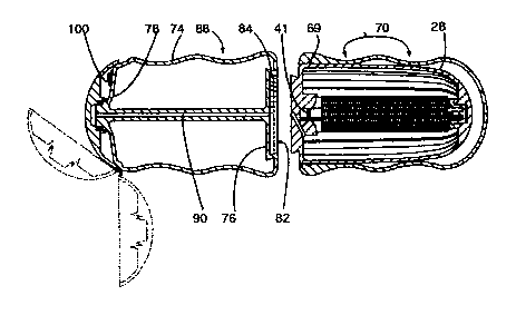
Figure 2 is a side sectional view of the floss container and dispenser of
Figure 1;
Figure 3 is a view similar to Figure 2 illustrating movement of the cover
portion
and associated cutter and the drawing being without shading for greater
clarity;
Figure 4 is an end view as seen from the left hand side of Figure 2 with the
cover in an open position;
Figure 5 is a side sectional view of an inner spool holder;
Figures 6 and 6A illustrate the insertion of the inner spool holder into an
outer
cage member;
Figure 7 is a side sectional view of the inner spool holder;
Figure 8 is a side sectional view of the inner spool holder and outer cage
with
the dispenser being in a non dispensing position;
Figure 9 is a view similar to Figure 1 illustrating the inner spool holder and
outer cage positioned to permit the dispensing of the floss;
Figure 10 is an exploded view of the floss and associated cog wheel and tooth
arrangement to permit dispensing of the floss; and
Figure 11 is a perspective view illustrating use of the device.
-3-

CA 02237024 1999-06-11
DESCRIPTION OF THE PREFERRED EMBODIMENTS
Referring to the drawings in greater detail and by reference characters
thereto,
there is illustrated in Figure 1 a floss container and dispensing device
generally
designated by reference numeral 10.
Floss container and dispensing device 10 has a first section 12 and a second
section 14 which are independent of each other and, when in an operative
position, are
joined only by the floss itself as will be discussed in greater detail
hereinbelow.
First section 12, as may be best seen in Figures 2, 3, 6 and 6A, comprises an
inner spool holder generally designated by reference numeral 18 and an outer
cage 20.
Inner spool holder 18 has a first end generally designated by reference
numeral 24, a
second opposed end generally designated by reference numeral 26, and a side
wall 28
extending therebetween. Formed in side wall 28 are a plurality of
longitudinally
extending slots 30.
Located at first end 24 is a recess 32 formed interiorly thereof. The
exteriorly
facing end wall 34, as may be seen in Figure 7, has an undercut side wall 36
for
reasons which will become apparent hereinbelow. A floss guide means comprising
a
channel 38 is provided in end wall 34.
Mounted interiorly of inner spool holder 18 is a floss spool generally
designated by reference numeral 40. Floss spool 40 comprises a core 42 having
floss 44 wrapped thereabout in a conventional manner. A groove 41 is provided
at
one end of core 42 for releasably retaining the floss spool by engagement with
a
protrusion at recess 32.
-4-

CA 02237024 1999-06-11
Second end 26 of spool holder 18 also has a recess 48 formed therein. As may
be best seen in Figure 10, core 42 has a slot formed in one end thereof. A cog
wheel 52 has a top wall 54 with a recess 56 formed therein and a diametrically
extending member 58 being designed to fit within slot 50 in core 42. Extending
downwardly from top wall 54 are a plurality of teeth 60 and with cog wheel 52
terminating in a shaft 62.
Formed on the interior surface of second end 26 are a plurality of teeth 66
which surround recess 48. As may be seen, the arrangement is such that shaft
62 will
fit within recess 48 and teeth 60 on cog wheel 52 engage teeth 66. Teeth 60
and 66
may be formed so as to be somewhat tapered to provide for a smoother meshing
between the teeth.
Outer cover 20 is designed to extend about first end 24 and side wall 28 of
inner spool holder 18 and be retained thereon by means of an annular
protrusion 69 on
side wall 28. A plurality of concave finger gripping portions generally
designated by
reference numeral 70 are provided on the exterior surface thereof.
Second section 14 is comprised of a first end wall generally designated by
reference numeral 76 and a second end wall 78 having a side wall 74 extending
therebetween.
At first end 76, there is provided a recess which is defined by an undercut
side
wall 84. The arrangement is such that first end 24 of first section 12 will
fit within
recess 82 such that the two sections may be held together.
-5-

CA 02237024 1999-06-11
Side wall 74 also is provided with a plurality of concave finger gripping
portions 88. Formed interiorly of second section 14 is an interior channel 90
to
receive the floss by means of slot 91 formed in side wall 74.
At second end 78, second section 14 is provided with a cover 92 connected by
a hinge 94 to the main body portion.
As may be seen, the two sections 12 and 14 can be connected to form a
compact unit for storage.
In operation, and as may be best seen in Figures 8 and 9, floss spool 40 is
normally maintained in a locked position by means of the interengagement of
teeth 60
on cog wheel 52 and teeth 66 at second end 26. However, a squeezing action on
side
wall 28 will cause the disengagement of teeth 60 and 66 to thereby permit
rotation of
floss spool 40 and the withdrawal of floss 44 through floss guide channel 38.
After the required amount of floss is withdrawn, release of pressure on side
wall 28 will again cause the interengagement of teeth 60 and 66.
The free end of the floss withdrawn from floss spool 44 is then fed into
interior
channel 90. Once cover 92 is closed in position, the floss is securely held in
place and
the length of floss between first section 12 and second section 14 may then be
utilized.
As may be seen in Figure 11, the finger gripping portions 70 of sections 12
and 14 are
designed to be gripped by the last three fingers leaving the index forgers
free to act as
a guide for the floss.
After use, the used segment of floss may be removed and cut by means of
cutting means 100.
-6-

CA 02237024 1999-06-11
The system is easily used and is particularly useful for those with reduced
manual dexterity such as those who suffer from arthritis or the elderly. The
amount of
floss needed during each session is reduced by one half to as much as two
thirds of the
usual recommendation that 18 inches of floss is needed each time.
To install a new floss spool 40, side wall 28 may be flexed and the old floss
spool removed through slots 30 and a new floss spool inserted.
It will be understood that the above described embodiments are for purposes of
illustration only and that changes and modifications may be made thereto
without
departing from the spirit and scope of the invention.

Representative Drawing
A single figure which represents the drawing illustrating the invention.
Administrative Status

2024-08-01:As part of the Next Generation Patents (NGP) transition, the Canadian Patents Database (CPD) now contains a more detailed Event History, which replicates the Event Log of our new back-office solution.

Please note that "Inactive:" events refers to events no longer in use in our new back-office solution.

For a clearer understanding of the status of the application/patent presented on this page, the site Disclaimer , as well as the definitions for Patent , Event History , Maintenance Fee  and Payment History  should be consulted.

Event History

Description Date
Revocation of Agent Requirements Determined Compliant 2021-04-01
Inactive: IPC from MCD 2006-03-12
Time Limit for Reversal Expired 2005-06-13
Letter Sent 2004-06-14
Grant by Issuance 2000-10-17
Inactive: Cover page published 2000-10-16
Pre-grant 2000-07-13
Inactive: Final fee received 2000-07-13
Notice of Allowance is Issued 2000-05-10
Letter Sent 2000-05-10
Notice of Allowance is Issued 2000-05-10
Inactive: Approved for allowance (AFA) 2000-04-20
Amendment Received - Voluntary Amendment 2000-03-13
Inactive: S.30(2) Rules - Examiner requisition 1999-11-18
Inactive: Office letter 1999-06-23
Revocation of Agent Requirements Determined Compliant 1999-06-23
Amendment Received - Voluntary Amendment 1999-06-11
Revocation of Agent Request 1999-06-11
Application Published (Open to Public Inspection) 1999-03-12
Letter sent 1999-02-01
Advanced Examination Determined Compliant - paragraph 84(1)(a) of the Patent Rules 1999-02-01
Inactive: Adhoc Request Documented 1999-02-01
Inactive: RFE acknowledged - Prior art enquiry 1999-01-29
Inactive: Correspondence - Formalities 1999-01-12
Inactive: Advanced examination (SO) 1999-01-12
Early Laid Open Requested 1999-01-12
Request for Examination Requirements Determined Compliant 1999-01-12
Inactive: Advanced examination (SO) fee processed 1999-01-12
All Requirements for Examination Determined Compliant 1999-01-12
Request for Examination Received 1999-01-12
Inactive: First IPC assigned 1998-08-05
Classification Modified 1998-08-05
Inactive: IPC assigned 1998-08-05
Filing Requirements Determined Compliant 1998-07-22
Inactive: Filing certificate - No RFE (English) 1998-07-22
Application Received - Regular National 1998-07-20

Abandonment History

There is no abandonment history.

Maintenance Fee

The last payment was received on 2000-06-12

Note : If the full payment has not been received on or before the date indicated, a further fee may be required which may be one of the following

  • the reinstatement fee;
  • the late payment fee; or
  • additional fee to reverse deemed expiry.

Please refer to the CIPO Patent Fees web page to see all current fee amounts.

Fee History

Fee Type Anniversary Year Due Date Paid Date
Application fee - small 1998-06-12
Advanced Examination 1999-01-12
Request for examination - small 1999-01-12
MF (application, 2nd anniv.) - small 02 2000-06-12 2000-06-12
Final fee - small 2000-07-13
MF (patent, 3rd anniv.) - small 2001-06-12 2001-06-07
MF (patent, 4th anniv.) - small 2002-06-12 2002-05-21
MF (patent, 5th anniv.) - small 2003-06-12 2003-06-05
Owners on Record

Note: Records showing the ownership history in alphabetical order.

Current Owners on Record
D. LLOYD FLANAGAN
Past Owners on Record
None
Past Owners that do not appear in the "Owners on Record" listing will appear in other documentation within the application.
Documents

To view selected files, please enter reCAPTCHA code :


To view images, click a link in the Document Description column. To download the documents, select one or more checkboxes in the first column and then click the "Download Selected in PDF format (Zip Archive)" or the "Download Selected as Single PDF" button.

List of published and non-published patent-specific documents on the CPD .

If you have any difficulty accessing content, you can call the Client Service Centre at 1-866-997-1936 or send them an e-mail at CIPO Client Service Centre.


Document
Description 
Date
(yyyy-mm-dd) 
Number of pages   Size of Image (KB) 
Abstract 1998-06-12 1 24
Description 1998-06-12 5 236
Drawings 1998-06-12 5 53
Claims 2000-03-13 3 95
Claims 1999-01-12 1 43
Cover Page 1999-03-26 1 48
Abstract 1999-06-11 1 19
Description 1999-06-11 7 261
Claims 1999-06-11 2 62
Drawings 1999-06-11 4 119
Cover Page 2000-09-22 1 40
Representative drawing 2000-09-22 1 16
Representative drawing 1999-03-26 1 3
Filing Certificate (English) 1998-07-22 1 174
Acknowledgement of Request for Examination 1999-01-29 1 172
Reminder of maintenance fee due 2000-02-15 1 113
Commissioner's Notice - Application Found Allowable 2000-05-10 1 163
Maintenance Fee Notice 2004-08-09 1 172
Fees 2003-06-05 1 22
Correspondence 1999-01-12 3 63
Correspondence 1999-06-23 1 8
Correspondence 1999-06-11 2 49
Correspondence 1999-06-23 1 8
Fees 2000-06-12 1 25
Fees 2001-06-07 1 23
Fees 2002-05-21 1 24
Correspondence 1998-07-24 1 27
Correspondence 2000-07-13 1 30