Note: Descriptions are shown in the official language in which they were submitted.
CA 02237070 1998-OS-27
WO 97/23329 PCT/SE96/01724
1
Method for treatment of wood
TECHNICAL FTELD
The present invention relates to a method for treatment of
one or more wood elements by isostatic pressurization, the
wood element being placed in a bed of a pressure medium and
the pressure medium being pressurized, the pressure medium
thus transmitting the pressure to the wood element.
The method is well suited for drying of wood with a high
moisture content. The method is particularly well suited for
drying with a subsequent impregnation of kinds of wood which
are otherwise difficult to impregnate, for example spruce.
BACKGROUND ART-AND PROBLEMS
It is previously known to change the properties of wood
products by pressure treatment. Pressure treatment has been
used, for example, for compressing and hardening of wood. In
this connection, particularly good results have been
obtained by treatment by means of isostatic pressurization
of the wood elements. In a previously known method, the wood
elements to be treated are placed surrounded by a pressure
medium in a compression chamber. The pressure medium
consists of a plurality of adapted rubber elements, shaped,
for example, as balls, elongated strips or cubes. The
pressure medium is delimited in the pressure chamber from a
working fluid, for example hydraulic oil, by an elastic
membrane. By pressurizing the working fluid by means of a
hydraulic pump, the worked-up pressure is transmitted to the
pressure medium. The pressure medium forms around the wood
elements and brings about a uniform compression thereof.
This results in a permanent compression and hardening of the
wood elements.
A disadvantage with the prior art is that the liquid and
moisture contents of the wood elements prior tothe pressure
treatment must be reduced to a level acceptable for the
CA 02237070 1998-OS-27
WO 97/23329 PCT/SE96/OI724
2
pressure treatment. The reason therefor is that the incom-
pressible liquid during the pressurization is contained in
the wood element, whereby compression of the wood element is
not possible. Thus, it has not been possible to pressure-
s treat freshly sawn timber or other wood products with too t
high a moisture ratio.
A closely related problem is that, with the previously known
technique, it has not been possible to utilize pressure
treatment for the very purpose of drying of wood elements.
To reduce the moisture ratio of wood products, it has
hitherto been necessary to use the traditional methods,
which are based on heating and/or air drying by means of
fans. These methods, however, are relatively time-consuming
and therefore cause high costs.
Another, and perhaps even more serious problem, which is a
consequence of the traditional drying methods, concerns the
subsequent impregnation of the dried wood products. This
often entails serious problems, since it is difficult to
cause the. impregnating agent to penetrate sufficiently deep
into the wood. Impregnation of wood products, such as sawn
timber, is often desirable. The impregnation aims at
increasing the resistance of the wood products to certain
processes, such as bacterial or fungus attack, causing
degradation in the wood. Usually, the preserving agent is
dissolved in a liquid, which by means of various methods Zs
brought to penetrate into the wood. The penetration may be
achieved, for example, by soaking the wood products or by
driving in the impregnating liquid by means of an over-
pressure. In the latter case, the impregnation is usually
preceded by vacuum treatment of the wood products.
The penetration of the liquid into the wood may take place "
either by diffusion or flow. In the case of diffusion, the
liquid penetrates very slowly into the wood by means of the '
concentration of the impregnating solution. In the case of
penetration by flow, on the other hand, the liquid may quite
rapidly penetrate into the wood by utilizing the fibres and
CA 02237070 1998-OS-27
WO 97/23329 PCT/SE96/01724
3
pores occurring in the wood. During impregnation, flow
penetration is preferable to diffusion penetration owing to
the higher rate of penetration.
In coniferous wood, more than 90~ of the wood consists of
wood fibre, so-called tracheids. In the live tree, the
purpose thereof is, among other things, to conduct liquid.
The tracheids consist of about 3 millimetres long, elongated
hollow fibres. They are arranged essentially parallel to the
longitudinal direction of the tree and each other and are
mutually axially displaced. Liquid may be transported from
one tracheid to an adjacent one via so-called pores. The
pores, which may be of different kind, for example ring
pores or simple pores, constitute openings in the tracheid
wall_ The pores usually comprise some type of closing
member, a so-called pore membrane. Because the pore mem-
branes open and close the pores, liquid is allowed and
prevented, respectively, from passing from one tracheid to
another.
During impregnation of sawn timber, the liquid penetrates
very rapidly from the end surfaces of the wood elements. The
longitudinal tracheids are cut off there and the liquid
enters easily. To allow the liquid to pass into the wood,
from one tracheid to another, the pores must be open. Sooner
or later the liquid encounters a tracheid where all the
pores are closed and the penetration thus stops.
It has proved that traditional drying of coniferous wood
causes closing of the pores. When the wood dries, the pore
membrane is displaced from a central position and closes the
pore opening. What causes the membrane to move are capillary
forces in the water which is dried away. When the membrane
has clogged the pore opening, it is impossible to move the
membrane even if the wood is subjected to very high
pressure. This is probably due to the membrane adhering to
the pore wall and to the fact that a bond in the form of
hydrogen bridges arises therebetween.
CA 02237070 2001-05-14
4
The above reasoning i.s an explanation why, after traditional
drying of softwood, i.t is so difficult to cause impregnating
liquid to penetrate =>uff:i.ciently deeply into the wood.
Further, it has been known for a long time that it is
considerably more difficult to impregnate spruce than pine.
This is due, among other things, to the fact that a larger
number of pores close during drying of spruce than of pine,
and to pine having fewer and smaller pores.
A special problem with previously known drying methods is
thus that they render the subsequent drying of the wood
considerably more dif:f:icult. This is particularly true of
certain kinds of wood, such as spruce.
The object of the present invention is to provide a method
for treatment of wood which allows pressure treatment to be
used for thE: drying of the wood and which makes possible a
considerably simplified impregnation of the dried wood.
THE SOLUTION
According to the pre:~ent invention, there is provided a
method for treatment of one or more wood element=s by
pressurization, COmp11S1T1g the steps of embedding the wood
element in a pressure medium, increasing the pressure in
the pressure medium, whereby the wood element is compressed
by transmitting the pre~~sure via the pressure medium to the
wood element, and reducing the pressure in the pressure
medium, whereby the wood element is relieved, characterized
in that the wood element. contains liquid which during the
compression is driven out by the fact that the pressure
medium comprises a. plurality of solid bodies with
intermediate spaces, t:he solid bodies having a sufficient
CA 02237070 2001-05-14
4a
hardness to maintain t=he intermediate spaces between the
bodies when subjected to pressures over 400 bar, whereby
the solid bodies transmit the pressure to the wood element,
such that a pressure difference arises between the wood
element and said ,paces when the pressure medium is
pressurized,. which pressure difference drives the .Liquid
from the wood element. to the spaces.
According tc~ the present invention, there is also provided
a method for treatment of a wood element, having a high
moisture ratio, exceeding 30%, characterized by the steps
of
embedding the wood element in a pressure medium
comprising a plural=,_ty of solid bodies with intermediate
spaces,
pressurizing the pressure medium such that the solid
bodies transmit pressure to the wood element, whereby the
wood element, is comp=ressed and a pressure difference arises
between the wood element and said spaces, said pressure
difference driving :li.quid from the wood element to the
spaces,
during the pres~~urization draining liquid that has
been driven out from the wood element, and
removing the pressurization, whereby the wood
element is relieved and expands.
Since the pressure med:_um comprises solid bodies, it is
ensured that the spacer between the bodies are maintained
also during the pressui:ization of the pressure medium. 'This
CA 02237070 1998-OS-27
WO 97/23329 PC'f/SE96/01724
makes possible the pressure difference, which is necessary
for driving out the liquid, during the compression of the
wood element. The method according to the invention thus
allows wood elements to be dried by means of pressure treat-
5 ment. Such pressurized drying is significantly faster than
the prior art drying methods. Drying of freshly sawn timber
to a moisture ratio of about 30~, which previously, for
example in a drying furnace, took up to 24 hours, can be
carried out in less than 2 minutes with the method according
to the invention.
The raised pressure which is obtained during the compression
phase may be maintained in the pressure medium and in the
wood element during a certain predetermined holding time
prior to the beginning of the pressure relief phase. In this
way, it is ensured that the desired quantity of the liquid
has time to penetrate out of the wood element.
The solid bodies included in the pressure medium may consist
of a large number of different materials and they may have
different hardness depending on under what maximum pressures
they are to be used. Some materials which have proved to be
particularly suitable are polymers, sand, glass, stainless
steel, bronze and aluminium oxide. In those applications of
the method where only lower pressures are utilized, the
solid bodies may have a hardness according to the interna-
tional IRH scale of IRH shore A 95° or more. If higher
pressures are used, the hardness should preferably exceed
TRH shore D 80°. In this connection it should be noted that
the TRH shore D scale represents a higher hardness interval
than the IRH shore A scale.
Further, the solid bodies may have an infinite number of
geometrical shapes. They may be completely asymmetrical and
mutually different, which is the case, for example, with
grains of sand, but they may also be symmetrical and iden-
tical, for example as steel balls. The size of the solid
bodies is of importance to the result. Too large bodies
cause visible impressions in the surface of the wood
CA 02237070 1998-OS-27
WO 97/23329 PCT/SE96101724
6
element, whereas too small bodies or grains make the escape
and removal of liquid between the spaces and from the wood
element difficult. Attempts have shown that solid bodies
with a diameter or mesh size smaller than 10 mm are
suitable. Particularly favourable results are obtained if ,
the grain size is between 0.1 and 5 mm.
The fact that the wood elements during the relief phase
restore their original shape in this context means several
advantages. For one thing, in many respects, the same pro-
perties as traditionally dried wood are imparted to the wood
elements. For example, wood dried according to the invention
exhibits no difference from other wood, from the strength
point of view or any other structural engineering point of
view, which makes it possible to use it as ordinary wood
without further adaptation. Further, the expansion of the
wood element during the relief phase contributes to make
possible a significantly simpler impregnation of the wood
element.
In use of the method, during the compression, a considerable
proportion of pore membranes present in the wood element may
be caused to leave their pores. The pore membranes are
flushed away with the aid of the relatively fast flowing
liquid, whichwas present in the wood element from the
beginning and which is pressed out during the compression.
As is clear from the above, the pore membranes constitute
one of the most serious reasons for traditionally dried wood
being so difficult to impregnate. As a considerable propor-
Lion of the pore membranes according to the invention are
removed from the pores, a significant proportion of the
tracheids will, after pressurization, lie open to the im-
pregnating liquid. In this way, the resistance to impregna-
tion by means of a flowing liquid is considerably reduced.
The impregnating liquid can therefore, in a simpler and
faster manner, penetrate considerably deeper into the wood '
than what was previously possible. The method according to
this embodiment makes possible an impregnating efficiency
which has not been possible at all in the past.
CA 02237070 1998-OS-27
WO 97/23329 PCT/SE96/01724
7
Further, the rate of pressure increase and the maximum
pressure may be adjusted to control the proportion of pore
membranes which are caused to leave their pares. This con-
trol makes possible, for example, removal of an optimum
proportion of pore membranes without damaging the wood in
other respects. The maximum pressure as well as the rate of
pressure increase are chosen depending of the kind of wood
and the dimension of the wood. Attempts have shown that
pressures of between 400 and 1500 bar are often suitable.
Particularly favourable results have been achieved at
between 700 and 1100 bar.
Still more important for obtaining a well-balanced blow-out
or flushing away of pore membranes is the rate at which the
pressure in the pressure medium and the wood element is
increased. The faster the pressure increase, the higher the
liquid flow and the larger the proportion of removed pore
membranes. Too rapid pressure increase, however, may damage
the tracheids and other wood components. During tests, rates
of pressure increase of between, on average, 2 and 40
bar/second, preferably between 10 and 25 bar/second have
proved to be suitable.
According to one embodiment of the invention, an impregna-
ting liquid may be allowed intothe woodelement during the
relief. This offers a method of treatment for drying and
impregnation which is considerably faster and more efficient
than prior art methods. Drying and impregnation, which
according to the prior art take from several hours up to
several days, are carried out in just a few minutes using
the method according to the invention. If a sufficiently
large proportion of pore membranes are removed during the
liquid expulsion, the embodiment also entails a considerably
larger impregnation depth and a higher impregnation
efficiency than what has been possible so far.
Further, the impregnating liquid may be supplied to the
spaces in the pressure medium when the pressure medium is
pressurized. The impregnation according to this embodiment
CA 02237070 1998-OS-27
WO 97/23329 PCT/SE96/0172a
8
takes place by driving the impregnating liquid, during the
relief of the wood element, into the wood element by means
of the pressure difference which arises between the spaces
and the wood element during expansion thereof. In this way,
a simple and efficient treatment cycle is obtained without ,
interruption or reloading. In addition, the energy which is
used for building up the liquid expulsion pressurization is
utilized also for the impregnation. This renders the process
considerably more effective in relation to the prior art,
where the drying energy cannot be used in any way during the
pressure impregnation.
BRIEF DESCRIPTION OF THE DRAWING
Exemplifying embodiments of the method according to the
invention will be described below with reference to the
accompanying drawings.
Figure 1 is a schematic cross section through a press for
carrying out the method according to the invention.
Figure 2 is a schematic longitudinal section, greatly
amplified, through part of a wood element when, embedded
into a pressure medium, it undergoes a treatment according
to the invention.
The press shown in Figure 1 comprises a pressure chamber 1,
which is defined by an upper 2 and a lower 3 part. By
separating the two parts 2 and 3, the pressure chamber is
opened, thus providing a possibility of inserting and
withdrawing the wood elements 4 which are being treated. In
the pressure chamber 1 an elastic diaphragm 5 is arranged.
The diaphragm 5 is attached to the upper part 2 such that it
is fixed between the upper part 2 and the lower part 3 when
the pressure chamber 1 is closed and such that the lower
part of the pressure chamber is exposed when the chamber is
opened. When the pressure chamber 1 is closed, the diaphragm
5 delimits one primary 1a and one secondary 1b compartment.
The primary compartment la of the pressure chamber communi-
CA 02237070 1998-OS-27
WO 97/23329 PCT/SE96/OI724
9
Gates, via a channel 6, with a hydraulic unit 7 in the form
of a high-pressure pump.
Further, in the secondary compartment 1b of the pressure
,. 5 chamber 1, two elongated wood elements 4 are arranged. These
are embedded into a pressure medium 8, which completely
surrounds the wood elements 4. A pressure vessel 9 for
storage and pressurization of impregnating liquid, is placed
outside the press and communicates, via an impregnation
valve 10, with distribution conduits 11, arranged in the
pressure medium, in the vicinity of the wood elements. The
pressure vessel 9 is also connected to a pump (not shown)
for pressurization of the impregnating liquid. The distri-
bution conduits 11 are provided with small spray holes (not
shown) and extend on two sides of each wood element alorg
essentially the whole length of the element. Likewise, in
the secondary compartment 1b and in the vicinity of the wood
elements 4, several draining pipes 12 {only one being shown)
are arranged. The draining pipes 12 are provided with
openings (not shown) and communicate via a drain valve 13
with the outside of the press. Both the impregnation valve
10 and the drain valve 13 may be controlled to open and
close from the outside of the press.
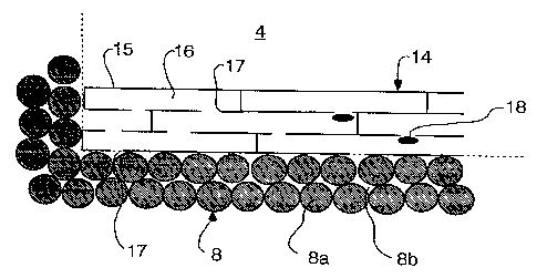
The part of a longitudinal section of a wood element 4,
schematically shown in Figure 2, comprises a number of
elongated tracheids 14. Each tracheid comprises walls 15, an
inner void 16 and openings 17 in the walls. At two of the
openings, or the pores 17, a pore membrane is disposed. To
the left in the figure it is indicated that several of the
tracheids nearest the end of the wood element are cut and
have no end wall. The wood element 4 is surrounded, on the
two sides shown, by the pressure medium 8. This comprises a
plurality of glass balls 8a with intermediate free spaces
8b. The diameter of the glass balls is around 1 mm.
It is described below how two wood elements 4 are treated
according to one exemplifying method according to the
invention. When the upper part 2 of the pressure chamber 1
CA 02237070 1998-OS-27
WO 97/23329 PCT/SE96/OI724
is removed, the wood elements 4 are lifted into the lower
part of the pressure chamber 1. The wood elements 4 consist
of planks of sapwood from spruce and have a moisture ratio
exceeding 30~. Normally, the moisture ratio for freshly sawn
5 sapwood of spruce is between 100 and 150. The moisture .
ratio may, of course, vary depending on the kind of wood and
the preceding treatment, but generally the moisture ratio ,
before the treatment should not be too low. The moisture
ratio, which is reduced during the liquid expulsion,
10 influences the rigidity of wood. Too low a moisture content
causes the wood to become more rigid, which counteracts the
resumption of the original shape by the wood elements during
the relief. Too low a moisture ratio may thus entail a
lasting compression and hardening of the wood elements which
3.5 is not desirable in this connection.
The wood elements 4 are placed on a bed of glass balls 8a,
whereupon glass balls are poured over them so that they are
surrounded by these glass balls on all the sides. Also the
distribution pipes 11 are arranged in the bed, so that the
spray holes become evenly distributed along the wood
elements 4 and at an appropriate distance therefrom. Under
the wood elements the draining pipes 12 are arranged, with
the openings for draining the spaces 8b in the pressure
medium 8. The draining pipes 22 may possibly be arranged
such that a majority of the openings are concentrated in the
vicinity of those locations of the wood elements 4 which,
during the compression, give off more liquid, for example
the short sides of the wood elements.
When the pressure medium bed is arranged, the pressure
chamber 1 is sealed by lifting the upper part 2 with the
diaphragm 5 onto the lower part 3 and securing it thereto.
Thereafter, the hydraulic unit 7 is started, whereby hydrau-
lic oil is pumped via the channel 6 into the primary com-
partment 1a of the pressure chamber 1. When the primary r
compartment is filled with hydraulic oil, the pressure is
increased by pumping in additional oil. The raised pressure
is transmitted via the diaphragm 5 and the pressure medium 8
CA 02237070 1998-OS-27
WO 97/23329 PCT/SE96/OI724
11
in the secondary compartment 1b to the wood elements 4.
Since the friction between the glass balls 8a is relatively
low, an isostatic pressure arises in the secondary compart-
ment. At the same time, the spaces between the balls are
,. 5 retained. The pressure which is transmitted via the
diaphragm causes an equilibrium of forces between all the
balls which are in mechanical contact with each other. Tn
this way, the pressure is transmitted isostatically from the
diaphragm via the balls to all the surfaces of the wood
element 4. The gas pressure in the spaces 8b between the
balls 8a is not changed to any significant degree during the
pressure-increase phase. The atmospheric pressure which
prevails prior to the start of the hydraulic unit 7 is
retained in all essentials during the compression phase.
G~hen the glass balls 8a now press on the surfaces of the
wood elements 4, the same high pressure arises in the wood
elements 4 as in the pressure medium 8. In this way, liquid,
which exists freely in the voids 16 of the tracheids 15, is
pressurized to this high pressure. A pressure difference
thus arises between the liquid in the wood elements 4 and
the spaces 8b between the balls 8a in the pressure medium 8.
This difference in pressure drives liquid to move from the
wood element 4 to the spaces 8b in the pressure medium 8.
The liquid primarily leaves the wood elements through the
possible outlets which cause the lowest flow resistance.
Thus part of the liquid passes out through tracheids 14
which are cut off at the end of the wood elements. Part of
the liquid flows out via pores 17 at the surface of the wood
elements and part of the liquid diffuses out through the
tracheid walls 15. During its flow from the interior of the
wood elements to the surfaces thereof, liquid tears off pore
membranes 18 from the tracheid walls 15 at the pores 17. The
' torn-off pore membranes 18 are carried with the liquid from
tracheid 14 to tracheid and thus follow the liquid out of
the wood elements 4.
During the pressurization, the drain valve 13 is open. Part
of the liquid which leaves the wood elements 4 is transpor-
CA 02237070 1998-OS-27
WO 97/23329 PCT/SE96/01724
12
ted via the spaces Sb away from the wood elements and is
collected by the draining pipes 12 with their draining
openings. The drained-off liquid is passed via the draining
pipes 12 and the valve 13 away from the pressure chamber 1.
The draining of the spaces Sb may possibly be accelerated by
vacuum suction of the spaces 8b with the aid of the vacuum
pump (not shown), which may be connected to the drain valve
13.
To obtain a good result when driving off liquid and pore
membranes during the compression phase, the pressurization
rate and the maximum pressure are chosen to suit the wood
elements in question. During treatment of sapwood from
spruce with an initial maisture ratio exceeding 100, the
pressure is raised from atmospheric pressure by about 5
bar/second to about 900 bar. The pressurization parameters
are also chosen in dependence on the available pressure
medium. Thus, for example, balls of steel or aluminium oxide
withstand pressures exceeding1000 bar, whereas solid bodies
of, for example, polymers are not used for pressures
exceeding about 500 bar.
The high pressure which is achieved during the pressuriza
tion phase is now maintained during a certain predetermined
time. This is done in order to give the desired quantity of
liquid ample time to penetrate out from the wood elements.
The duration of the holding time varies from case to case
and is determined on the basis of, among other things, the
kind of wood, the moisture ratio as well as the rate of
pressure increase and the maximum pressure. By choosing a
longer holding time, it may be possible to allow the rate of
pressure increase and the maximum pressure to be_lower. This
results in a treatment which, admittedly, is somewhat slower
but which is also more lenient to the fibre structure in the '
wood.
Before or during the compression phase and the holding time,
the impregnating liquid in the pressure vessel 9 has been
pressurized to a pressure which is considerably higher than
CA 02237070 1998-OS-27
WO 97/23329 PCT/SE96/01724
13
the pressure which prevails in the pressure medium 8 and the
wood elements 4. When the compression phase and the holding
time are completed, the drain valve 13 is closed. Thereafter
the impregnating valve 10 is opened. The pressurized impreg-
nating liquid thus flows out through the distribution tubes
11 and is distributed via the spray nozzles out into the
spaces 8b near the wood elements 4. Since the pressure of
the impregnating liquid in the spaces 8b is now higher than
the pressure in the wood elements, the impregnating liquid
penetrates into these. To ensure that a sufficient quantity
of impregnating liquid penetrates sufficiently deep into the
wood, the pressure difference between the impregnating
liquid in the spaces and the wood elements is maintained for
a certain holding time. When this holding time is completed,
25 the secondary compartment lb is relieved by evacuating
hydraulic oil from the primary compartment. During the
relief phase, the wood elements 4 again expand into their
original shape. This leads to an additional pressure diffe-
rence between the interior of the wood elements and the
spaces 8b filled with impregnating liquid. This pressure
difference now drives additional impregnating liquid into
the wood elements. Since a considerable part of the pore
membranes is flushed away, impregnating liquid may penetrate
far into the wood elements without difficulty. Only a
relatively small pressure difference is necessary to obtain
a satisfactory impregnation, where liquid penetrates into
the centre of the wood elements. The relief can be carried
out relatively rapidly, whereby the pressure can be reduced
by about 20-50 bar/second.
After completed relief, when the pressure in the primary 1a
and secondary 1b compartments and in the wood element again
is around 1 bar, the upper part 2 of the pressure chamber is
removed, whereupon the wood elements can be removed.
During the impregnation, the moisture ratio of the wood
again rises. Normal values of the moisture ratio, both
during traditional impregnation and the method described
above, are around 35 - 125. Tf an impregnated product with
CA 02237070 1998-OS-27
WO 97/23329 PCT/SE96/01724
14
a lower moisture ratio is desired, the wood elements may be
dried in traditional manner. It is also possible, however,
after the active components in the impregnating liquid have
reacted with the wood, to dry the wood elements againby
means of pressure treatment. The redundant impregnating
liquid thus runs out during the compression phase, wherafter
no liquid is added during the relief phase.
The method described above is only one example of treatment
of wood according to the invention. The method may be varied
in a plurality of different ways.
For example, wood elements of many other kinds of wood, such
as pine, oak, birch, larch, beech, aspen and alder may be
treated. In addition to being derived from the sapwood, the
treated elements may also be derived from the heartwood or
constitute a combination thereof.
The treatment must not comprise the impregnationphase, but
the wood elements may be relieved without any supply of
impregnating liquid. This result in a very fast and effec-
tive drying of the wood elements.
The method of supplying impregnating liquid to the spaces
when the wood elements are pressurized can be varied in many
ways. The impregnating liquid may, for example, be pumped in
via the draining pipes. It is also possible, instead of
supplying the liquid from an external pressurized container,
to place a flexible container in the pressure medium bed.
This flexible container is filled with impregnating 11qu1d
before the compression phase. During the compression phase
the liquid is prevented from penetrating out into the bed in
that the impregnation valve is closed. The liquid in the
flexible container is thus pressurized to essentially the '
same pressure as that which prevails in the wood elements.
When the compression phase with the subsequent holding time '
is completed, the impregnation valve is opened whereby the
impregnating liquid spreads in the spaces of the pressure
medium. When the liquid has spread, the wood elements are
CA 02237070 1998-OS-27
WO 97/23329 PCT/SE96101724
relieved whereby they expand to their original shape. This
results in a pressure difference between the spaces and the
wood elements which drives the impregnating liquid into the
wood elements.
5
Further, it is not necessary to drain away the liquid which
is driven out of the wood elements during the compression.
It is also possible to reuse this liquid by allowing concen-
trated impregnating liquid, after the liquid expulsion, to
10 mix therewith in the bed. Thereafter, the liquid with im-
pregnating agent is returned into the wood elements during
the relief.
The method of driving out the liquid from the wood element
15 is best suited for driving out so-called free water. This is
water which, prior to the drying, exists freely in the
fibres of the wood and which is not bound in the cell walls
of the wood.
r