Note: Descriptions are shown in the official language in which they were submitted.
CA 02237~2l l998-0~-l2
WO97tl8080 PCT~S96/18081
Method and Apparatus ~or Extracting Liquid
from a Liquid Cont~;ning Slurry
TECHNICAL FIELD
~ A method for extracting liquid from a liquid-
cont~;n;~ slurry, and the apparatus for performing the
above method; the apparatus including at least one press
assembly having a foraminous cylindrical contA;ne~ provided
with an inlet and an outlet, mixing and pressing means
mounted for movement within the foraminous cont~in~ for
batch processing slurry by sequentially iY; nq and pressing
the slurry within the foraminous container, and feed means
for continuously feeding slurry under pressure through the
inlet to cause liquid within the slurry to be expressed
through the foraminous con~; ner.
BACKGROUND OF THE INVENTIO~
Apparatuses are well known in the art for separating
liquids from slurries. For example, juice presses for
separating juice from a fruit are known and examples are
shown in U.S. patents 1,971,546; 5,275,097; and 5,365,838.
While apparatus for separating ~uice ~rom fruit was
developed in Biblical times, more recen~ly such apparatus
has been used in other industries. For example, it is well
known in the art that sewage sludge may be dewatered. (In
this application, the ~ -vdl of liquid from a slurry may
be referred to a dewatering.) Examples of sewage
dewatering apparatus are shown in U.S. patents 5,263,411;
5,307,739; and British ~ 119 670 A. A review of these
prior patents, as well as many others, shows that problems
~ exist in the art. The product, from which liquid has been
extracted, may be referred to as cake. The cake is dropped
' 35 or otherwise discharged into a bin or other receiving
device. If one needs to further extract liquid, the cake
CA 02237~21 1998-0~-12
WO97/18080 2 PCT~S96/18081
must be broken up and conveyed or forced into another
apparatus. This is often impossible, or at best difficult.
In single stage batch presses such as the piston
presses shown in U.S. patents 5,275,079 and 5,307,729; many
products compact so densely that they seal off all exit
paths for the escaping liquid. Also, in these designs, it
is necessary to clean the filtering media usually at the
end of each press cycle. This is done by vibrators,
shakers, scrapers, etc. These vibrators, shakers and
scrapers are also used to discharge the filter cake from
the press as a filter cake frequently sticks badly in batch
presses.
A further disadvantage of piston presses such as the
type shown in '739 is that it is necessary to provide a
valve downstream of the piston to maintain the slurry which
is being pressed within the cylinder. As the literature
indicates, it is necessary to provide a valve capable of
withstanding high pressures and frequently the cost of the
downstream valve equals or exceeds the cost of the rest of
the apparatus. Continuous presses are also known which
apply progressively higher pressures. Examples are shown
in U.S. patents 1,971,546; 5,365,838; and GB 2 ll9 670 A.
The auger-type devices shown in '546 and '670 cannot apply
a relatively high pressure on the slurry. In addition,
auger presses do not aggressively mix the slurry for
opening up new passageways for the discharge of material.
The '838 reference discloses in Figure 2 a liquid
extracting apparatus which applies progressively higher
pressures to a slurry as it is moved away from the inlet on
a continuous belt. This design is also defective in that
it does not aggressively mix the slurry as it moves from
one pressing station to the next for opening up new
passageways for the discharge of the material. Also,
during the continuous operation, the filter conveyor can
clog, and it is not possible to clean the filtering media
until the final pressing stage has been accomplished.
CA 02237521 1998-0~-12
W O 97/18080 3 PCTAUS96/18081
It is possible to get more liquid out of a slurry by
squeezing it a bit, breaking up the initial cake formed
after the initial squeeze, squeezing again, etc. Several
presses work on this principle. Two noteworthy examples
are the horizontal bas~et presses of Bucher Guyer in
Switzerland, and the pneumatic tank presses of Wilmes in
Germany. These presses do the entire dewatering process
with the body of the press itself, the problem being the
wasted time and effort associated with tying up a
relatively large machine during the final stages of
pressing, during which time a relatively small quantity of
liquid is being expressed.
It is perceived by the present inventors that the
product should be removed from the press and transferred to
another machine so that the primary presser may be kept
employed upon fresh slurry. The secondary presser may be
much smaller than the first, as the volume or slurry is
greatly reduced when the bulk of liquid is removed in the
initial press.
O B JE CT S AN D SU~DM~RY OF T HE IN VEN TI ON
It is an object of the present invention to provide
two or more serially arranged slurry presses for extracting
liquid from slurry wherein there is a quick and efficient
transfer of slurry from one press to another.
It is a further object of the present invention to
provide a self-cleaning piston press assembly.
It is an additional object o~ the present invention to
provide a new apparatus and method for extracting liquid
from a liquid containing-slurry, which includes a valveless
piston press assembly, the press assembly including a
foraminous cylinder having an inlet and an outlet, and a
piston assembly moveable within the foraminous container
and having open and closed positions, which piston assembly
may act as a valve.
_ _ _ _ _
CA 02237~21 1998-0~-12
WO97/18080 4 PCT~S96/18081
It is yet another object of the present invention to
provide a piston press assembly for extracting liquid from
a liquid containing slurry, the press assembly including a
two-part piston assembly mounted within a foraminous
cylindrical container having an inlet and an outlet, which
two-part piston assembly when moved towards the inlet will
open up to permit slurry to pass through, which slurry is
broken and mixed as it passes through, the two-part piston
assembly when moved towards the outlet pressing the broken-
up and mixed slurry to cause further liquid to be radially
expressed through the foraminous container, and the second
stage dewatered slurry to be forced through the outlet.
It is a still further object of the present invention
to provide method and apparatus which continually presses
first stage slurry, and batch presses successive stages of
slurry, the apparatus including feed means for continuously
f~e~inq slurry under pressure through the inlet of a first
foraminous container to cause liquid within the slurry
upstream of a ;xing and pressing means to be expressed
through the foraminous container, the i~;ng and pressing
means including a two-part piston assembly which is moved
within the foraminous container for batch processing the
slurry by breaking it up and mixing it as the two-part
piston assembly is moved in a first direction and for
subsequently pressing the broken-up and mixed slurry to
cause further li~uid to be radially expressed through the
foraminous container.
The above objects, as well as other objects of the
present invention are obtained by providing a plurality of
interconnected press assemblies, each having a foraminous
cylindrical container, the outlet and inlet of successive
containers being connected so that slurry will flow from
the first container to the last cont~ine~, each of the
containers having mixing and pressing apparatus mounted
therein, and there being feed means for initially
introducing slurry under pressure into the foraminous
container of the first press assembly. With this design
_
CA 02237S21 1998-0~-12
W O 97/18080 5 PCT~US96/18081
two-stage dewatering takes place in the first press
assembly and additional dewatering takes place in each
succeP~; ng press assembly at progressively higher
pressures, with the material being aggressively mixed
within each foraminous container and as it passes from one
~ foraminous container to the next. The mixing and pressing
apparatus within each foraminous cylinder is able to pump
or otherwise force the dewatered mass into a pipe or other
device after dewatering is finished. As these press
assemblies each are self-cleaning, it can be appreciated
that each press assembly arranged in series can discharge
automatically and clean its filter element at the same
time.
While the foregoing design can extract nearly all of
the liquid from a liquid-cont~; n; ng slurry, there are
practical limitations on the size of the diameter of the
foraminous cylinder. Thus, as each of the mixing and
pressing devices during pressing exerts its own force, it
also exerts the force of all upstream pressing devices plus
the force of the initial feed means. Therefore, very
substantial forces can be achieved when a series of press
assemblies are interconnected. In order to prevent the
wall of the foraminous cylinder from becoming distorted, it
is therefore necessary to limit its ~; diameter
consistent with accepted design practices. However,
capacities can be increased by connecting columns of
se~uentially arranged presses together with the discharges
of the first press in each column going into a common
manifold, which common manifold in turn feeds the inlet of
sucr~ ;ng presses.
In summary, it can be seen that by utilizing the
apparatus briefly outlined above, many of the problems
existing in the prior art may be overcome.
CA 02237~2l l998-0~-l2
WO97118080 6 PCT~S96/18081
BRIE~ DESCRIPTION OF THE DRAWINGS
FIG. l shows a cross-sectional view of a pre~s
assembly of this invention, the press assembly including a
cylindrical foraminous container having an inlet and an
outlet, the outlet being shown to the left, and includes
m; ~; ng and pressing means which are shown in an
intermediate position before slurry has been introduced
into the press assembly.
FIG. 2A shows a closeup of the ;x;ng snd pressing
means in the position shown in FIG. l.
FIG. 2B shows is a section taken generally along the
line 2B-2B in FIG. 2A.
FIG. 2C shows the ix;ng and pressing means after it
has been fully extended towards the outlet causing the
mixing and pressing means to become closed 80 that slurry
may be introduced into the foraminous container upstream of
the m; X; ng and pressing means.
FIG. 2D shows the mixing and pressing means moving
upstream after slurry has been introduced behind it, the
movement of the mixing and pressing means causing slurry to
be forced through the mixing and pressing means to
thoroughly mix it.
FIG. 2E shows the mixing and pressing means moving
downstream to press the material downstream of the mixing
and pressing means, additional slurry being introduced
upstream of the mixing and pressing means.
FIG. 3 shows three press assemblies sequentially
arranged with the outlet of the first press assembly being
connected to the inlet of the second press assembly, and
with the outlet of the second press assembly being
connected to the inlet of the last press assembly, the
mixing and pressing means of the first and second press
assemblies being moved in a downstream direction to extract
liquid, and the mixing and pressing means of the last press
assembly being held in its fully extended closed position.
CA 02237~21 1998-0~-12
WO97/18080 PCT~S96/18081
FIG. 4 is a view similar to FIG. 3 and shows the
beginning of the expulsion cycle of the last press assembly
while the first and second press assemblies are shown in
their fully extended positions holding pressure.
FIG. 5 is a view similar to FIG. 4 but showing the
~ expulsion cycle of the last press assembly near completion.
FIG. 6 shows a schematic of the control circuit for
the apparatus shown in FIGS. 3 - 5.
FIG. 7 is a view illustrating how a plurality of
series of press assemblies can work together.
FIG. 8 is a flow chart illustrating the operation of
the FIGS. 3 - 5 embodiment.
DETAILED DESCRIPTION
The apparatus of this invention is indicated generally
at lO in FIG. 3 and includes at least one press assembly
indicated generally at 12. A number of press assemblies
may be arranged sequentially as shown in FIGS. 3 - 5. In
addition, a plurality of columns of sequentially-arranged
press assemblies may be utilized as indicated in FIG. 7.
Each of the press assemblies shown in the various figures
is structurally the same, although the controls for the
press assemblies may vary. A single press assembly will
now be described with reference to FIG. l.
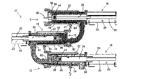
Each press assembly includes a central foraminous
container or filter cylinder 14, and mixing and pressing
~n~, indicated generally at 16. The mixing and pressing
~n~ in turn include a two-part piston assembly, indicated
generally at 18; and extensible and retractable means,
indicated generally at 20. The foraminous cylinder is
mounted within an outer housing 22 provided with a liquid
outlet 24. The cylinder 14 has a slurry inlet opening 26
at its upstream end, and a compressed slurry ou~let 28 at
its downstream end, which is to the left in FIG. l. The
filter cylinder is, in the preferred embodiment,
CA 02237~21 1998-0~-12
WO97/18080 8 PCT~S96/lS081
constructed of metal screen, in particular "V" or "wedge
wire" screen.
The extensible and retractable means 20 preferably
consists of a double-acting hydraulic ram assembly
including a hydraulic cylinder 30, the anchor end of which
is secured to a mount 32. A piston rod 34 extends from the
rod end of the hydraulic cylinder 30, the rod being driven
by a piston 36 within the hydraulic cylinder 30. Hydraulic
lines 38 and 40 are interconnected with cylinder 30 and are
controlled via solenoid operated control valves (not shown)
to cause the piston or actuator rod 34 to be extended or
retracted. The end of the actuator rod which extends
outside of the hydraulic cylinder has a reduced diameter
threaded end portion 42 which passes through a ring 44, the
ring being secured about the threaded end portion 42 by a
nut 46. The annular outer surface of the ring 44 is in
turn welded or otherwise rigidly secured to the inside of
an elongated ram tube 48 which passes through a seal 50 and
bearing 52 upstream of the inlet opening 26. The seal and
bearing assembly 50, 52, and the mount 32 are both carried
by a steel mounting tube 56 which is disposed about the ram
tube 48 and the extensible and retractable cylinder means
20.
A cylindrical transition member 56 is rigidly secured
by welding or the like to the outer housing 22 adjacent the
inlet opening 26. The other end of the transition member
56 has a flange 58. A flange 60 on the mounting tube 54 is
secured to the flange 58 by means of bolts 62.
The end of the ram tube 48 which passes through
foraminous cylinder 14 receives a welded assembly indicated
generally at 64. The welded assembly includes a threaded
plug 66, vanes 68, and a ring 70. Plug 66 is screwed into
ram tube 48. Vanes 68 are mounted on the face 66.l of the
threaded plug. Ring 70 is supported by the ends of the
vanes away from the threaded plug. The face 66.l of plug
66 and the face 48.l of ram tube 48 act as an inner pis~on
within cylinder 14. As can best be seen from FIG. 2A, ring
CA 02237~2l l998-0~-l2
W0~7/18080 9 PCT~S96/18081
70 has a diameter greater than the effective diameter of
the vanes 68. Loosely supported on the vanes 68 between
ring 70 and plug 66 is an annular member 72 which acts as
an outer piston within cylinder 14. The annular piston 72
has a large circular opening 72.1 of a diameter less than
that of ram tube 44.
With reference now to FIGS. 2D and 2E, the end of ram
tube 48, plug 66, and annular piston 72 form a two-part
piston assembly which is closed when the extensible and
retractable means 20 is extended as shown in FIG. 2E, and
which is open when the extensible and retractable means is
retracted as shown in FIG. 2D. Ring 70 and vanes 68
comprise lost motion connection means, the annular outer
piston 72 abutting the face 44.1 of tube 44 when being
moved in the downstream direction shown in FIG. 2E.
The annular outer piston 72 has a scraping surface
72.2 so that as the annular piston is moved towards inlet
26, slurry upstream of the annular piston will be scraped
away from the surface of foraminous cylinder 14 and forced
through the large opening 72.1 of the annular piston. The
annular piston is preferably made of a tough plastic, but
other suitable materials may be used. In addition, the
annular piston has one or more O-rings 74 (only one being
illustrated), the function of the O-rings being to rub
along the surface of foraminous cylinder 14 as the piston
72 is moved in either direction for the purpose of cleaning
the surface of the cylinder. The operation of the two-part
piston assembly will be described in greater detail below.
Downstream of the foraminous cylinder and the
downstream end of the outer housing is a removable exit
door 76 which is held in its assembled position by pivoted
bolts 78 and nuts 80. The exit door has an exit opening 82
to which a suitable conduit 84 may be interconnected.
Disposed within the foraminous container at the downstream
end adjacent the exit door 76 is a stop ring 86, the
purpose of which is to act as a closing means for the
two-part piston assembly. Thus, it limits the movement of
CA 02237~2l l998-0~-l2
WO97/18080 10 PCT~S96/18~81
the annular piston 72 as the hydraulic ram is extended to
ensure that the two-part piston assembly 18 is closed,
closure being necessary during initial start-up.
~he operation of a single press assembly 12 will now
be described. At the commencement of the first cycle of
operation, the two-part piston assembly 18 will be extended
all the way towards the discharge, the stop ring 86 closing
the two-part piston assembly. After the two-part piston
assembly has been fully extended, as sensed by limit switch
88, it will be held in its extended closed position. Thus,
limit switch 88 senses the exLL~- ~ downstream position of
the tube 44, switch 88 sensing by infrared light, or by any
other conventional manner. The two-part piston assembly
closes the press assembly without the use of a separate
valve. The operation of external pump 90 is now commenced,
and slurry to be dewatered is pumped from reservoir 92
through inlet 94 in transition member 84 and into inlet
opening 26 of foraminous cylinder 14. The pump 90, which
operates continuously during the operation of the press, is
preferably a positive displacement type, such as a gear
pump, having a relief discharge pressure set at
approximately 30 psi (approximately 207 kPa~.
As cylinder 14 fills up, liquid is radially expressed
from the slurry through foraminous cylinder 14 and into
outer housing 22, such li~uid then passing through liquid
outlet 24 at the bottom of the housing, and into contact
with a flow sensor 96 which senses the flow rate of the
liquid being expressed from the slurry. The flow sensor is
interconnected with a controller which may be a computer
98. When liquid flow is essentially stopped, hydraulic
fluid will be introduced through line 36 to cause piston
rod 34 and two-part piston assembly 18 to be quickly
retracted.
Initially, during the retraction cycle, the lost
motion coupling means 68, 70 will permit the downstream
face 72.3 of annular piston 72 to contact ring 70, opening
up the two-part piston assembly. After the two-part piston
CA 02237~21 1998-0~-12
WO 97/18080 . 11 PCT/USg6/18081
assembly has opened, continued movement of rod 34 in the
right-hand direction will cause first-stage dewatered
slurry material to be forced through the large circular
- opening 72.1, thoroughly mixing and breaking up the first-
stage dewatered material. This causes great agitation and
reforming of the cake or dewatered slurry, thereby opening
up new pathways for liquid to escape, among other things.
As the annular piston 72 moves, the scraper ring 74 cleans
the inside of filter cylinder 14 of particles which can
blind the holes of the screen.
The movement of the actuator rod and two-part cylinder
assembly will continue until it approaches the inlet
opening, at which time limit switch sensor 100 will sense
the right-hand position of the tube 48. Information from
sensor 100 will be communicated to controller 98, which
will in turn cause hydraulic fluid to be introduced into
cylinder 30 behind piston 36 to cause actuator rod 34 to
move in a downstream direction to the left (in FIG. 1).
This will initially cause the face 44.1 of the closed inner
piston to contact the annular piston, thereby closing the
opening within the two-part piston assembly. As the
pressure within cylinder 30 is limited to approximately 30
psi (approximately 207 ~Pa) the two-part piston assembly
will slowly force the material ahead of it, causing second
stage slurry in front of the two-part piston assembly to be
slowly compresses, extracting additional liquid, and
forcing the second stage dewatered slurry through exit
opening 82 and conduit 84.
When used as a single-stage press, conduit 84 may act
as a restrictor. Alternatively, it may have a valve to
ensure that sufficient pressure is exerted upon the mixed
material within the foraminous cylinder on the downstream
side of the two-part piston to cause further liquid to be
extracted within the first foraminous cylinder. During
~35 this pressing cycle slurry to the upstream side of the two-
part piston assembly will be subjected to a press force by
pump 90. Thus, the mixed second-stage material downstream
CA 02237~21 1998-0~-12
W097/18080 12 PCT~S96/18081
of the two-part piston assembly will be subjected to both
pump pressure and ram pressure. It should be appreciated
from an inspection of FIG. l that the material discharged
from press 12 will again be broken up and mixed during this
discharge cycle. The foregoing operation will be repeated
a number of times until all of the desired slurry has been
processed, material to the upstream side of the two-part
piston continually being subject to pressure from pump 90.
The apparatus just described continuously presses slurry to
the upstream side of the two-part piston assembly, and
slurry passing through the two-part piston assembly is
batch processed by mixing of the initially dewatered slurry
as it passes through the circular opening 72.l, and by
pressing the mixed material.
After all of the slurry has been processed, it may be
desired to clean the apparatus. To this end, nuts 80 are
loosened, and the exit door may be removed. The filter
cylinder 14, and all of the parts therein, can now be
easily removed for cleaning and replacement.
With reference now to FIGS. 3 - 6, a series of
interconnected press assemblies are illustrated, conduits
84 interconnecting the outlet of one container to the inlet
of a successive container so that slurry will flow from the
first to the last containers. Feed means (not shown)
similar to pump means 90 is provided for introducing slurry
under pressure into the inlet of the first foraminous
container, the pressure also being approximately 30 psi.
Flow sensors 96 and 102 (FIG. 6) are also provided to sense
the flow of fluid from the first and last foraminous
containers, the sensors in turn being interconnected with
controller 98. Controller 98 is also interconnected via
control lines 104 to suitable solenoid operated valves for
controlling the flow of fluid into each of the cylinders 30
via lines 38 and 40.
The operation of the interconnected series of pump
assemblies can best be understood from the flow chart in
FIG. 8. At the commencement of operation, the controller
CA 02237~21 1998-0~-12
WO97/18080 13 PCT~S96/18081
will initially cause the two-part piston assemblies 18 for
each of the essentially identical press assemblies to move
to the fully extended downstream position where they will
close by stop ring 86. After all piston assemblies have
attained this position as sensed by limit switches 88, the
operation of pump 90 will commence forcing slurry from
reservoir 92 into the inlet of the first foraminous
cylinder causing liquid to be expressed from the cylinder.
During this initial phase the cylinders will be held in
their extended position. If no flow has commenced from the
outlet of the last press assembly, as sensed by flow sensor
102, as would be the case during start-up, the controller
98 is responsive to the liquid sensor 96. During the
initial dewatering cycle, the pump will continue to force
material into foraminous cylinder 14 of the first press
assembly until flow sensor 96 indicates that there is no
more liquid flowing through outlet 24 of housing 22 of the
first press assembly.
It is now necessary to start batch processing the
material initially received within the first press assembly
and this is done by retracting two-part piston assembly 18
of the first press assembly, causing material upstream of
the two-part press assembly to be forced through the
circular opening 72.l of the annular piston, thoroughly
mixing and breaking up this material. This operation will
continue until sensor lO0 indicates that the two-part
piston assembly is fully retracted. During start-up when
no flow has been sensed by flow sensor 102 of the last
press assembly, the mixing and pressing means 16 of every
press assembly, except for the last one, will operate
simultaneously. However, the two-part piston assembly 18
of the last press assembly will be held in its fully
extended position.
During continued initial operation, the two-part
piston assemblies will continue to extend and retract, the
initiation of the retraction step being under the control
of flow sensor 96 and the initiation of the extension step
CA 02237~21 1998-0~-12
WO97J18080 14 PCT~S96/1~081
being under the control of limit switch l00. During each
cycle of operation after the very first cycle of operation,
material will be mixed by passing it through the two-part
piston assembly during retraction, and will then be pressed
again during the subsequent extension step.
Each of the successive pistons operates at
successfully higher pre~sures. Thus, with reference to
FIG. 3, the operating pressure for cylinder 30 of the first
press assembly, shown at the bottom of the figure, is
approximately 30 psi (approximately 207 kPa~, the operation
of the next successive cylinder assembly is approximately
40 psi (approximately 276 kPa), and the operation for the
last cylinder assembly being approximately 50 psi (about
345 kPa~.
Once flow is sensed by flow sensor 102, a different
sequence of operations c~ ?nce. Thus, all of the
foraminous cylinders have now been filled with ma~erial and
the third stage material to the upstream side of the two-
part piston assembly in the last press assembly is
subjected to the total pressure of the pump and the two
upstream piston assemblies, causing additional li~uid to be
extracted from the mixed material within the third
foraminous cylinder. After flow is initially sensed by
sensor 102, each of the two upstream two-part piston
assemblies will now commence to cycle independently in the
manner indicated in FIG. 8. Thus, each upstream piston
assembly 18 will simply extend until limit switch 88 of the
respective press assembly senses the fully extended
position, at which time the two-part piston will be quickly
retracted until its fully retracted position is sensed by
the limit switch l00 of the respective press assembly.
Meanwhile, during this batch processing of partially
dewatered slurry, the pump continues to operate constantly
forcing slurry under pressure into the first foraminous
cylinder upstream of the first two-part assembly.
once the flow of li~uid is no longer sensed by flow
sensor 102, the two-part piston assembly of the last press
CA 02237~21 1998-0~-12
WO97/18~80 15 PCT~S96/18081
assembly will be quickly retracted as indicated in FIG. 4,
regardless of the position of the upstream piston
assemblies. After this retraction step, the piston of the
last cylinder assembly will then be extended forcing the
final stage dewatered slurry out of the foraminous cylinder
until the last two-part piston assembly is closed by stop
ring 86 of the last press assembly. The last piston will
act as a valve for all upstage press assemblies.
The operation of the press assemblies described above
will continue until all slurry material has been exhausted
from reservoir 92, and until no more liquid is sensed by
flow sensor 102. At this time, the exit doors of the
various press assemblies can be opened up for final
cleaning.
While the press assemblies, like that shown in FIG. l,
may be used in a series of three interconnected presses as
shown in FIGS. 3 - 6, they may also be used in a series of
two, or in longer series. In additions series presses may
be mounted in parallel as shown in FIG. 7, which shows two
parallel sets of three stage series presses with the outlet
of the first press assembly of each series being connected
to a common manifold 106, and the outlet for the second
press assembly in each of the series being connect to a
further common manifold 108. The outlet of the last press
in each series may di5charge the compacted and dewatered
slurry onto a conveyor belt llO for discharge into a
suitable receptacle 112. The various presses shown in FIG.
7 will be controlled in a manner similar to that previously
described except that the two-part piston assembly for each
press which discharges into a common manifold (such as 106
or 108) will be extended at the same time to prevent
backflow from the manifold into a preceding press.
~ Individual press assemblies can be connected together
in series, in parallel, or both to extract liquid from
slurry. This form of press assembly, particularly when
used in series, does not require an expensive valve as used
in prior art single stage press assemblies. By
CA 02237521 1998-05-12
W O 97/18080 16 PCT~US96tl8081
continuously extracting liquid from the initially
introduced slurry, and batch processing the slurry after
the initial slurry has been dewatered, improved liquid
extraction is achieved with no manual processing.
While a preferred form of this invention has been
described above and shown in the accompanying drawings, it
should be understood that applicant does not intend to be
limited to the particular details described above and
illustrated in the ac~u ~nying drawings, but intends to be
limited only to the scope of the invention as defined by
the following claims.
What is claimed is: