Note: Descriptions are shown in the official language in which they were submitted.
CA 02237569 1998-05-12
WO 97/18105 PCT/US96/12857
CARGO AREA I~I~in. lN~ SYSTEM FOR l'RUCR8
FIELD OF THE lNV~ lON
This invention relates to truck lighting
systems; more particularly, it relates to a lighting
system for the cargo handling area o~ a truck using
piped light.
BACRG~OUND OF THE 1N V ~ 1 ON
As is well-known, trucks having fully enclosed
cargo space within the truck body are provided with a
lighting system to facilitate loading and unloading of
the cargo. Typically, the truck body, especially with
long haul trucks, is long relative to its height and
width to provide the desired cargo capacity. The
longstanding practice in lighting the interior of the
truck body has been to use a plurality of incandescent
lamps mounted in the roof of the truck body and spaced
from each other from front to rear. Typically, the
lighting fixtures comprise a lamp housing recessed into
the roof and enclosing an incandescent lamp and having
a light distributing lens disposed on the housing
between the housing and the cargo space so it is
generally flush with the interior surface of the roof.
This arrangement provides the required illumination
without the light fixture intruding into the cargo
space.
T~e conventional incandescent lighting system
described above has been found to be unsatisfactory
~ because it is wasteful of energy, requires ongoing
maintenance and is sometimes used in such a manner that
CA 02237~69 1998-0~-12
WO97/18105 PCT~S96/12857
it constitutes a fire hazard. In refrigerated trucks,
i.e. those which have a refrigeration system for the
cargo space, the heat that the incandescent lamps
generate is largely dissipated into the refrigerated
cargo space thus requiring more energy for
refrigeration. Also, it is known that some truck
drivers like to increase the illumination in the cargo
space by replacing the st~n~A~d low wattage ;ncAn~escent
lamps with higher wattage lamps resulting in increased
heat generation and shortened bulb life. This practice
adds to bul~ replacement cost in maint~; n; ng the
lighting system. Additionally, the conventional
incandescent lighting system constitutes a fire hazard,
especially ~when the truck ~ody is loaded with cargo
l~ close to the incandescent lamp fixtures and the lights
are inadvertently left on for a long time. Such
conditions can cause truck fires which are not only
dangerous to life and limb ~ut also constitute increased
costs to the trucking industry by reason of loss and
increased insurance premiums.
There has ~een a longst~n~;ng need in the
truc~ing industry for a safe, effective and energy
efficient lighting system for the cargo space in a
container body of a truck.
In the prior art, certain fi~er optic or
"light pipe" systems have been proposed for use on
vehicles. The Johnson et al. patent 4,947,293 granted
August 7, l990 discloses a clearance lighting system for
a semi trail~r cargo container ~ody. The lighting
system includes a core light conducting material in the
form of an elongated light conducting strip provided
with a cladding material to provide a light guide. The
core and cladding are constructed to provide lateral
.
~ CA 02237~69 l998-0~-l2
2 3~? ~!97
P-317 TMI - 3 -
light emission as well as longitudinal propagation. A
light source is adapted to end-illuminate the light
guides for both sides of a container body from a single
light source. A similar system which also provides a
message panel is disclosed in Johnson patent 5,122,933
- granted June 16, 1992.
The Moore et al. patent 4,740,870 granted
April 26, 1988 describes a fiber optic lighting system
for boats. In this system, a plurality of fiber optic
cables extend from a central light source to respective
~ plurality o~ remote light fixtures to provide lighting
at different locations on the boat.
The Davenport et al. patent 4,811,172 granted
March 7, 1989 describes an optical fiber lighting system
particularly suited ~or automobiles and air craft. The
lighting system comprises subsystems suitable for high
and low beam illumination and rear illumination of an
automobile. Each subsystem comprises a high intensity
light source coupled to one end of each o~ a plurality
of light pipes with each having its other end positioned
relative to a re~1ective element and a lens. The
reflective elements are arranged to provide a prescribed
illumination pattern.
The Finch et al. patent 5,184,883 granted
February 9, 1993 discloses an automobile lighting system
similar to that described in the above-referenced
Davenport patent 4,811,172. The Finch et al. patent
describes an indicating device that comprises a shutter
having an opaque portion, a light blocking position in
which the opaque portion blocks the passage of light
from the output end of a light guide to a lens and a
AMENDED SH~T
I CA 02237~69 l998-0~-l2 ~ ~ ~
~WS 1 2 S~
P-317 TMI - 4 -
non-blocking position in which light is allowed to pass
through the indicating device to the lens.
U.S. Patent Application SN 08/327,202 (the
~202 application) Patent No. 5,483,427, assigned to the
assignee of the present invention, describes a cargo
area lighting system for trucks using piped light. The
'202 application discloses a light source mounted on the
truck body and plural lighting fixtures mounted to the
roof of the truck body. Each lighting fixture receives
light which is piped through a separate light pipe from
the source to the ~ixture. Two sets of lighting
fixtures are disposed in linear arrays extending along a
line from the front to the rear of the truck body. The
light pipes for one set of lighting fixtures are all
disposed within a first enclosure and the light pipes
for the other set of lighting fixtures are all disposed
within a second enclosure. Certain sections of the
enclosures have transparent lenses and certain light
pipes within the enclosures emit side light through
those lenses. A lighting fixture at the rear door of
the truck body has an optical switch for turning the
lighting fixture on or off.
A general object of this invention is to
provide an improved lighting system for the cargo space
of a truck which overcomes certain disadvantages of the
prior art.
SUMMARY OF THE lNv~-llON
In accordance with this invention, an improved
lighting system is provided for the cargo space of a
truck body. The lighting system provides desired levels
of illumination throughout the cargo space by using a
~MEN~F~ SH~T
~ CA 02237~69 l998-0~-l2 ~ ~ ~ ~ 7
H~JS 1 2 S~P ~gg7
P-317 TMI - 5 -
piped light system which is highly efficient, simple and
economical to install without intruding significantly
into the cargo space and which requires little
maintenance. By using light piped into the cargo space
there is virtually no heat dissipation from the lighting
system in the cargo space and therefore waste of energy
in refrigerated truck bodies is avoided, as compared
with incandescent lamps. Further, the risk of fire
hazard from the lighting system is eliminated.
In accordance with the invention, the lighting
system for the interior of a truck body comprises an
electrically energized light source mounted on the truck
body, elongated enclosures which both support the light
pipes along their lengths and which transmit laterally-
emitted light from the light pipes into the cargo space.
The enclosures include integral mounting flanges adapted
to fasten the enclosure to one of the floor, side walls,
front wall, rear wall and roof. The integral mounting
flanges allow the light fixtures to be easily assembled
into a new truck body or retrofit into the cargo space
of an existing truck body.
A complete understanding of this invention may
be obtained from the detailed description that follows
taken with the accompanying drawings.
DESCRIPTION OF THE DRAWINGS
30FIGURE 1 is a partially cut-away cross-
sectional schematic plan view of the lighting system;
FIGURE 2 is a partially cut-away cross-
sectional schematic plan view of an alternative
' ~ ~; r J,--J ,, ~
~ CA 02237~69 l998-0~-l2 ~ ~ 8 7
P-317 TMI - 6 -
installation of the lighting system;
-
FIGURE 3 i~ a cross-sectional view of an
enclosure of the embodiments of Figs. 1 and 2 taken
along line 3-3 of either Figure 1 or Figure 2; and
FIGURE 4 is a broken-out view of a light pipe
of Figure 1 or 2.
BEST MODE FOR CARRYING OUT THE lNv~NLlON
Referring now to the drawings, there is shown
an illustrative embodiment of the invention in a truck
body interior lighting system using piped light. It
will be appreciated as the description proceeds that the
invention may be used in other applications and may be
realized in different embodiments.
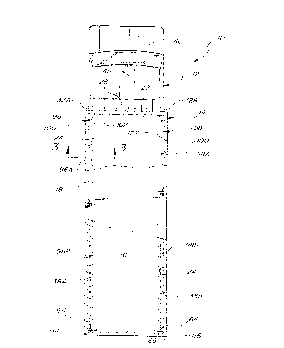
Figure 1 shows a trailer truck, generally
shown at 10, having a cab and a truck body, generally
indicated at 12 and 14, respectively. The truck body
includes a floor 16, a roof 18, a front wall 22, side
walls 24 and 24' and a rear wall 26. The truck body 14
encloses a cargo space which is refrigerated by a
refrigeration unit 28.
As shown in Fig. 2, the lighting system for
the cargo space, in accordance with this invention,
comprises at least one light source 32 suitably mounted
on the exterior of the front wall 22 above the
refrigeration unit 28. A first embodiment of the
lighting system, shown in Fig. 1, comprises two light
sources 32A, 32B mounted on the exterior of the front
wall 22 on either side of the refrigeration unit 28. A
A~DEO S~t~ET
CA 02237569 1998-05-12
WO97/18105 PCT~S96fI2857
second embodiment of the lighting system, shown in Fig.
2, comprises a single light source 32 mounted on the
exterior o~ the front wall 22 above the refrigeration
unit 28. Further, both the first and the second
embodiments of the lighting system comprise two light
pipes 38A, 38B, each of which extends from the light
source to a point adjacent the back wall 26. Both the
first and the second embo~; -nts also include a pair of
light pipe enclosures, generally indicated at 96 and 98,
respectively, which each contain a single light pipe.
The enclosure 96 includes enclosure sections 96A and 96B
and the enclosure 98 includes enclosure sections ~8A and
98B. The fiFst em~odiment of Fig. l shows enclosures 96
and 98 extending from two separate light sources, 32A
and 32B, respectively. The second embodiment of Fig. 2
shows enclosure 96 extending from the same light source
32 as enclosure 98.
The aforementioned components of the lighting
system will now be described in greater detail.
The light source 32 (32A and 32B in the second
embodiment) comprises a high intensity lamp of the type
described in the Ro~bins et al. patent 4,704,660 granted
25 November 3, 1987. Such light sources are available from
General Electric ~o~pAny and Lumenyte International
Corporation. ~ight sources of this type are commonly
known as "light engines". The light source 32 is
provided with a plurality of light ports each of which
is adapted for optical coupling with a light pipe in a
well-known manner. A light source is energized from the
truck electrical system through an electrical conductor
46 which includes a manually actuable switch 48 mounted
in the ca~ for operation ~y the driver. The light
source includes a voltage inverter for developing a high
CA 02237569 1998-05-12
WO97118105 PCT~S96/12857
voltage alternating current supply from the low voltage
DC supply from the truck.
The light pipes 38A and 38B are light
conductors of the type constructed of polymeric material
with a suitable cladding. The light pipes are
preferably of the type known as solid core semi-rigid
fiber optics such as that descri~ed in Zarian patent
4,957,347 granted September 18, l990. Such light pipes
are available from the Lumenyte International
Corporation. The light pipes are commonly referred to
individually as an "optic". The preferred light pipe
for this invention is of a type identified as side-light
fiber optic because it has the property of emitting
light radially through the cladding around the core and
also conducts light axially for emission through the end
of the core (referred to herein as a side-fire/end-fire
light pipe). It will be understood that the lighting
system of the first embodiment of this invention may
also use light pipes extending between the light source
and selected ones of the end-fire light fixtures which
do not provide side light emission but instead emit
light only from the output end (referred to herein as
end-fire light pipes).
Each of the light pipes has an input end
coupled with one of the ports of the light source and
has an output end.
As shown in Figs. l, 2, 3 and 4, the elongated
light pipe enclosures 96, 98 of the first and second
embodiments are each disposed around and supporting one
of the light pipes 38A, 38B. Each enclosure 96, 98 is
formed in two elongated, approximate 12 foot segments
35 96A, 96B, 98A, 98B. The segments are disposed end-to-
-
CA 02237~69 1998-0~-12
WO 97/I8105 PCT/US96/12857
end in pairs, with a single light pipe 38A, 38B
exten~;ng through eàch pair.
All o~ the first and second embodiment
enclosure sections 96A, 96B, 98A, 98B are of the same
construction. Accordingly, description of only
enclosure 96A will suffice and will be given with
reference to Figure 3.
As is best shown in Figure 3, the light pipe
enclosure section 96A of the first and ~c~n~
embodiments includes a pair of elongated mounting
flanges lO0, 102 adapted to fasten each enclosure
section into one of the upper corners formed where the
side walls 24, 24' and roof meet. Enclosure section 96A
is made of light transmissive material to allow
laterally-emitted light from light pipe 38A to pass into
the cargo space.
The light tr~n~r;~sive material forms a light-
transmitting panel 104 that is shaped to form a tubular
conduit 106 for supporting the light pipe 38A. The
conduit 106 includes an elongated longitudinally-
oriented slot 108. To install light pipe 38A in
enclosure section 96A, an installer need only snap the
length of light pipe 38A through the elongated slot 108
and into the tubular conduit 106.
Mounting flanges lO0, 102 project in radially
opposite directions from one another and integrally
extend from the tubular conduit 106 of each enclosure
~ segment on opposite sides of the longitll~; n~ l slot 108.
The flanges lO0, 102 are bent, along their lengths, so
that they extend outward at a right angle to one
another.
CA 02237569 1998-05-12
WO97/18105 PCT~S96/12857
-- 10 --
Enclosure section 96A is integrally extruded
from a single piece of light-tr~n! ;s~ive optical
material so as to have an elongated shape of a uniform
cross-section along its length. The tubular ron~ll;t 106
formed by the light-transmitting panel 104 includes a
plurality of elongated parallel light-dispersion grooves
llO. ~he grooves llO per~orm the dual function of
dispersing light, and hiding scratch marks that often
form during the extrusion process.
The first and second embodiment light pipes
38A, 38B are of the same construction. Accordingly,
description of only light pipe 38A will suffice and will
be given with reference to Figure 4.
Light pipe 38A includes a cladding with an
index of refraction which causes the cladding to emit
light laterally. As is best shown in Fig. 4, light pipe
20 38A includes angled cuts 112 disposed along its length.
The cuts 112 have depths, angles & spacing optimized for
even light distribution from along the length of light
pipe 38A. An end mirror 114 is disposed at the output
end 64 of light pipe 38A. The mirror 114 is positioned
perpendicular to the central longitll~;n~l axis of light
pipe 38A.
To operate the lighting system, the truck
driver operates the electrical switch 48 to turn on the
lighting system to illuminate the cargo space in the
truck body. When the switch 48 is turned on the light
sources 32A, 32B are energized and emit light from
respective ports to the input ends of the light pipes
38A and 38B.
CA 02237~69 l998-0~-l2~ q 6 ~ ~ 2 ~ 5 7
S~P 19~
\
P-317 TMI
Each light plpe 38A, 38B conducts llght along
lts length while emitting light laterally through its
respective enclosure sections 96A, 96B, 98A, 98B into
the cargo space. Light is laterally emitted at a
greater intensity at those points where diagonal cuts
112 are located. Light that is not laterally emitted is
conducted to the output end 64 of each light pipe 38A,
38B and is re~lected back into each light pipe 38A, 38B
by mirrors 114, 116 so that no light is lost from the
output ends 64.
Although the description of this invention has
been given with reference to a particular embodiment, it
is not to be construed in a limiting sense. Many
variations and modifications will now occur to those
skilled in the art. For a de~inition o~ the invention
reference is made to the appended claims.
hMENDED SHEET