Language selection

Search

Patent 2237868 Summary

Third-party information liability

Some of the information on this Web page has been provided by external sources. The Government of Canada is not responsible for the accuracy, reliability or currency of the information supplied by external sources. Users wishing to rely upon this information should consult directly with the source of the information. Content provided by external sources is not subject to official languages, privacy and accessibility requirements.

Claims and Abstract availability

Any discrepancies in the text and image of the Claims and Abstract are due to differing posting times. Text of the Claims and Abstract are posted:

  • At the time the application is open to public inspection;
  • At the time of issue of the patent (grant).
(12) Patent: (11) CA 2237868
(54) English Title: POULTRY SUPPORT RACK
(54) French Title: PORTE-VOLAILLE
Status: Expired and beyond the Period of Reversal
Bibliographic Data
Abstracts

English Abstract


A rack for supporting poultry in a baking pan during a cooking operation
includes two
slidably interconnected sections that can be pulled apart for disengagement
from the
turkey or chickent after the rack has been transferred from the baking pan to
a serving
tray or platter. Each section of the rack has a lifter handle to facilitate
the process of
lifting and moving the rack.


Claims

Note: Claims are shown in the official language in which they were submitted.

THE EMBODIMENTS OF THE INVENTION IN WHICH AN EXCLUSIVE
PROPERTY OR PRIVILEGE IS CLAIMED ARE DEFINED AS FOLLOWS:
1. A poultry support rack for use in a baking pan comprising:
first and second poultry support elements slidably joined together so as to be
capable of
complete separation for releasing the poultry;
said first poultry support element comprising first and second spaced parallel
poultry
support rails and a first handle means;
said second poultry support element comprising third and fourth spaced
parallel poultry
rails and a second handle means;.
said first and second rails being slidably overlappingly connected to said
third and fourth
rail so that the total rail length is variable to accommodate a range of
poultry dimensions;
said poultry support rack being positionable in a baking pan so that said
support rails are
in a horizontal plane overlying the bottom of the pan;
said first and second handle means being spaced apart for lifting the rack out
of the baking
pan and separating the first and second support elements whereby the poultry
an be left in
the space vacated by the separated support elements.
2. The poultry support rack of claim 1, wherein said first handle means is a
first inverted
U-shaped structure extending upwardly from said first and second rails; said
second
handle means comprising a second inverted U-shaped structure extending
upwardly
8

from said third and fourth rails.
3. The poultry support rack of claim 2, wherein each inverted U-shaped
structure is
oriented in a vertical plane when the rack is positioned in a baking pan.
4. The poultry support rack of claim 1, and further comprising a first pair of
feet carried
by said first and second rails proximate to said first handle means; and a
second pair
of feet carried by said third and fourth rails proximate to said second handle
means;
whereby said rails are elevated slightly above the bottom of a baking pan
during a
poultry baking operation.
5. The poultry support rack of claim 1 and further comprising a first
transverse spacer
member spanning the first and second rails proximate to the first handle
means; and a
second transverse spacer member spanning the third and fourth rails proximate
to the
second handle means;
6. The poultry support rack of claim 5, wherein each transverse spacer member
has
down-turned ends that form feet for elevating the respective rails slightly
above the bottom of
a baking during a poultry baking operation.
7. The poultry support rack of claim 1, wherein said first and second rails
and said first
handle means are formed out of a first single circular cross-sectioned rod;
and said third
and fourth rails and said second handle means are formed out of a second
single circular
cross-sectioned rod.
9

8. The poultry support rack of claim 1, and further comprising a first
elongated sleeve
carried by said third rail; said first rail being slidably telescoped within
said first sleeve;
and a second elongated sleeve carried by said fourth rail; said second rail
being slidably
telescoped within said second sleeve.
9. The poultry support rack of claim 8, wherein said rails and said sleeves
are located in a
common horizontal plan when the rack is positioned in a baking pan.
10.A poultry support rack for use in a baking pan, comprising:
first and second poultry support elements slidably interconnected so as to be
capable
of complete separation for releasing the poultry;
said first poultry support element comprising a first circular cross-sectioned
rod bent
to form a first upright inverted U-shaped handle having two lower ends, and
first and
second horizontal rails extending from the rod lower ends so that said rails
are
parallel;
said second poultry support element comprising a second circular cross-
sectioned rod
bent to form a second upright inverted U-shaped handle havig two lower ends,
and
third and fourth horizontal rails extending from the last mentioned rod lower
ends so
that said third and fourth rails are parallel; a first guide means carried by
said third
rail for slidably guiding said first rail; and a second guide means carried by
said fourth
rail for slidably guiding said second rail;
10

said first and second handles being movable toward each other to slide the
rails
horizontally for reducing the spacing between the handles;
said first and second handles being movable away from each other to slide the
rails
horizontally for increasing the spacing between the handles, and for
ultimately
separating the first and second support elements.
11

Description

Note: Descriptions are shown in the official language in which they were submitted.


~
CA 02237868 1998-OS-19
BACKGROUND AND SUMMARY OF THE INVENTION
This invention relates to a rack for supporting poultry in a baking pan during
a baking
(roasting) operation. The rack is equipped with lifting handles for taking the
rack and baked
poultry out of the baking pan after the cooking operation.
In conventional poultry baking, with a turkey, chicken, duck, etc., there is a
roast-baking
problem in transferring the baked poultry from the baking pan onto a serving
tray, cutting
board, or platter. The cooked poultry has a tendency to stick to the bottom of
the baking
pan. Also, the cooked poultry is difficult to pick up with conventional tongs
or other
implements that might be used to lift the poultry out of the pan.
Additionally, the cooked
poultry may fall apart during the process of being transferred out of the
baking pan, unless
the poultry is adequately supported.
The present invention is concerned with a rack that can be used to support
poultry in a
baking pan during a cooking (b;:king) operation. The rack has two lifter
handles for lift-
ing the poultry out of the pan after the cooking operation. A unique feature
of the rack is
that it is comprised of two slidably interconnected poultry support elements
that can be
completely separated from each other when the baked poultry has been
transferred to a
platter or serving tray.
The slidably interconnected support elements can be pulled apart from
underneath the
-1-

CA 02237868 1998-OS-19
r
the poultry, leaving the poultry resting on the platter or tray. A particular
advantage of the
rack is that the person does not have to touch the poultry; the person's hands
will not get
burned or covered with grease, because the only material in contact with the
poultry is the
rack.
Further features and advantages of the invention will be apparent from the
attached
drawings and description of an illustrative embodiment of the invention.
THE DRAWINGS
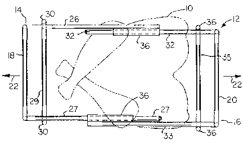
Fig. 1 is a top plan view of a rack embodying the invention. An item of
poultry supported
on the rack is shown in dashed lines.
Fig. 2 is a side elevational view of the Fig. 1 rack.
Fig. 3 is an end view of the Fig. I rack, taken on a reduced scale.
Fig. 4 is a fragmentary view showing a structural detail that can be used in a
rack
embodying the invention.
Fig. 5 is a view taken in the same direction as Fig. 4, and showing an
alternate form
that the structural detail can take.
Fig. 6 is a perspective view of an alternate rack embodying the invention.
Fig. 7 is a perspective view showing a variant of the rack structure depicted
in Fig. 1.
_2_

CA 02237868 1998-OS-19
1?ESCRIPTION OF A P FFFRRFn
EMBODIMENT OF THE INVENTION
Referring to Figs l and 2 of the drawings, there is showing a rack for use in
a baking
pan to support poultry during a baking operation. In Figs.l and 2 the poultry
is shown in
dashed lines and identified by numeral 10. The rack is generally indicated by
numeral 12.
The rack comprises a first poultry support element 14, and a second poultry
support
element 16. The two support elements 14 and 16 are slidably interconnected so
as to be
capable of complete separation by putting handle elements 18 and 20 away from
each other,
as indicated by arrows 22 in Fig. 2. The support elements 14 and 16 can thus
be pulled
away from positions underlying the poultry, leaving the poultry resting on the
support surface
24 (Fig.2. The rack can be used baking a turkey in a baking pan, and also for
transferring a
cooked turkey, or other item of poultry, from the baking pan to a platter,
after which the
support elements 14 and 16 can be pulled apart, so that the turkey is left
resting on the
platter, e.g. support surface 24.
Support element 14 comprises a circular cross-sectioned rod bent to form an
upright in-
verted U-shaped handle 18 and two horizontal rails 26 and 27 extending from
the handle
lower ends so as to be in parallelism with each other. A single rod is
preferably used to
form the rails and the handle.
Rails 26 and 27 are interconnected by a transverse spacer rod 29 having its
ends turned
down to form feet 30. The spacer rod tends to keep rails in parallelism. Feet
30 elevate
-3-

CA 02237868 1998-OS-19
the rails above the support surface 24, whereby the poultry has a lessened
tendency to stick
to the bottom of the baking pan when the rack is positioned in the pan, i.e.
during a baking
operation.
Support element 16 comprises a second circular cross-sectioned rod bent to
form an up-
right inverted U-shaped handle 20 and two horizontal rails 32 and 33 extending
from the
lower ends of handle 20 so as to be in parallelism with each other. Element 16
is prefer-
ably formed out of a single circular cross-sectioned rod.
Rails 32 and 33 are interconnected by a transverse spacer rod 35 located
proximate to
handle 20. The ends of rod 35 are turned down to form two feet 36. Rod 35
tends to keep
rails 32 and 33 parallel. Feet 36 serve to elevate rails 32 and 33 about
support surface 24.
Rails 32 and 33 are slidably joined to rails 26 and 27 by means of two
cyclindrical
sleeves 36 suitably joined to rails 26 and 33. Rails 27 and 32 are slidable in
sleeves 36,
whereby handles 18 and 20 can be moved toward each other or away from each
other for
changing the size (length) of the rack, and also for achieving a complete
separation of
support elements 14 and 16, e.g. when it is desired to disengage the rack from
the baked
poultry without disturbing the position of the poultry to any significant
extent.
Fig. 7 fragmentarily shows an alternate arrangement wherein sleeves 36 are
carried by
rails 32 and 33; rails 26 and 27 are slidable in the sleeves. The Fig. 7
arrangement is the
functional equivalent of the Fig. 1 arrangement.
-4-

CA 02237868 1998-OS-19
The rack can be employed as a poultry support device in a baking pan during a
poultry
cooking operation. The rack with the poultry supported on rails 26, 27, 32,
33, is placed
in the baking pan, after which the pan is placed in an oven to achieve the
cooking operation.
Periodically the turkey (poultry) is basted, as per the usual practice. The
rack is advantageous
during the basting operation in that the turkey is slightly elevated above the
bottom wall of
the pan so that basting juices are somewhat more accessible to the tip of the
barter. Juices
can drip from the turkey and collect on the pan bottom wall for pick up by the
barter.
After the baking operation the pan, with the turkey and rack, can be lifted
out of the oven,
using insulated gloves. The rack, with the turkey thereon, can then be
transferred from the
pan to a tray or platter or cutting board, using the lifter handles 18 and 20.
Alternately, the
rack, with the turkey thereon, can be lifted out of the pan and transferred to
serving tray,
platter or cutting board while the pan remains in the oven.
The rack can be removed from the baked turkey by pulling the poultry support
elements
14 and 16 apart, using the lifter handles 18 and 20. When elements 14 and 16
are completely
separated they can be readily removed from the turkey. As handles 18 and 20
are pulled in
opposite directions the turkey is automatically lowered onto the tray,
platter, cutting board or
similar support surface 24 (Fig. 2). The entire operation is relatively quick
and efficient;
the turkey offers negligible resistance to separation of the two support
elements 14 and 16.
Figs. 4 and S show alternate mechanisms for slidably interconnecting the rails
26, 32 or
27, 33. As shown in Fig. 4, rail 32 carries two annular rings 38 that form the
equivalent
-5-

'' CA 02237868 1998-OS-19
r
of the above-mentioned sleeve 36. Rail 26 is slidable in the annular rings.
Fig. 5 shows an arrangement wherein rail 26 is a tube slidably accomomodating
the rod-type
rail 32. When the tube-rod concept is used, the poultry support element 14 can
be formed
of tubular stock instead of rod stock. Each rail 26 or 27 will be a tube, and
each rail 32 or
33 will be a rod.
Fig. 6 shows a variant of the invention that uses a somewhat different handle
construc-
tion. As shown in Fig. 6, the leftmost poultry support element 14 comprises a
horizontal
U-shaped rod that forms two rod type rails 26, 27 and a connector rod 50. The
associated
handle 18a comprises a vertical rod extending upwardly from connector rod 50
and
terminating in a handgrip 52.
The rightmost poultry support element 16 comprises a horizontal U-shaped rod
that forms
two rod-type rails 32.33 and a connector rod 54. The associated handle 20a
comprises a
vertical rod terminating in a hand grip 56. Sleeves 36 are welded or otherwise
attached to
rails 32 and 33 for slidable accommodation of rails 26 and 27.
Functionally, the Fig. 6 rack structure is equivalent to the rack structure
depicted in Figs 1
through 3. Either structure can have a range of sizes suited to particular
poultry dimensions.
Tyically, the rack will have an extended length of about twelve inch and a
transverse width
of about five or six inch. Rails 26, 27, 32, 33 will be spaced far enough
apart (about five
inch) so that the rails act as a cradle for the turkey, chicken, etc.
-6-

CA 02237868 1998-OS-19
It will be seen that the invention can be practiced in various forms and
configurations.
Preferably the components are formed out of cylindrical rod stock. However,
other
shapes and types of stock can be used, e.g. square rod stock, square tubing,
or rectangular
bar stock.

Representative Drawing
A single figure which represents the drawing illustrating the invention.
Administrative Status

2024-08-01:As part of the Next Generation Patents (NGP) transition, the Canadian Patents Database (CPD) now contains a more detailed Event History, which replicates the Event Log of our new back-office solution.

Please note that "Inactive:" events refers to events no longer in use in our new back-office solution.

For a clearer understanding of the status of the application/patent presented on this page, the site Disclaimer , as well as the definitions for Patent , Event History , Maintenance Fee  and Payment History  should be consulted.

Event History

Description Date
Time Limit for Reversal Expired 2005-05-19
Letter Sent 2005-05-19
Inactive: Office letter 2005-04-14
Inactive: Payment - Insufficient fee 2005-04-12
Inactive: Reversal of will be deemed expired status 2005-03-03
Inactive: Adhoc Request Documented 2005-02-23
Letter Sent 2004-05-19
Inactive: Late MF processed 2004-04-27
Inactive: Reversal of will be deemed expired status 2004-04-20
Inactive: Delete abandonment 2004-01-05
Inactive: Office letter 2004-01-05
Inactive: Abandoned - No reply to Office letter 2003-12-11
Inactive: Office letter 2003-09-11
Revocation of Agent Requirements Determined Compliant 2003-09-11
Revocation of Agent Request 2003-07-22
Inactive: Office letter 2003-06-13
Inactive: Office letter 2003-06-12
Revocation of Agent Request 2003-05-23
Letter Sent 2003-05-20
Grant by Issuance 2002-06-11
Inactive: Cover page published 2002-06-10
Pre-grant 2002-03-13
Inactive: Final fee received 2002-03-13
Notice of Allowance is Issued 2001-09-28
Letter Sent 2001-09-28
Notice of Allowance is Issued 2001-09-28
Inactive: Approved for allowance (AFA) 2001-09-13
Amendment Received - Voluntary Amendment 2000-06-20
Letter Sent 1999-11-26
Application Published (Open to Public Inspection) 1999-11-19
Inactive: Cover page published 1999-11-18
Request for Examination Received 1999-10-19
Request for Examination Requirements Determined Compliant 1999-10-19
All Requirements for Examination Determined Compliant 1999-10-19
Inactive: IPC assigned 1998-08-14
Inactive: First IPC assigned 1998-08-14
Classification Modified 1998-08-14
Inactive: Filing certificate - No RFE (English) 1998-07-29
Filing Requirements Determined Compliant 1998-07-29
Application Received - Regular National 1998-07-28

Abandonment History

There is no abandonment history.

Maintenance Fee

The last payment was received on 2002-03-12

Note : If the full payment has not been received on or before the date indicated, a further fee may be required which may be one of the following

  • the reinstatement fee;
  • the late payment fee; or
  • additional fee to reverse deemed expiry.

Please refer to the CIPO Patent Fees web page to see all current fee amounts.

Fee History

Fee Type Anniversary Year Due Date Paid Date
Application fee - small 1998-05-19
Request for examination - small 1999-10-19
MF (application, 2nd anniv.) - small 02 2000-05-19 2000-05-16
MF (application, 3rd anniv.) - small 03 2001-05-22 2001-05-15
MF (application, 4th anniv.) - small 04 2002-05-20 2002-03-12
Final fee - small 2002-03-13
Reversal of deemed expiry 2003-05-20 2003-05-23
MF (patent, 5th anniv.) - small 2003-05-20 2003-05-23
Owners on Record

Note: Records showing the ownership history in alphabetical order.

Current Owners on Record
VIOLETTE KASSASEYA
Past Owners on Record
None
Past Owners that do not appear in the "Owners on Record" listing will appear in other documentation within the application.
Documents

To view selected files, please enter reCAPTCHA code :


To view images, click a link in the Document Description column. To download the documents, select one or more checkboxes in the first column and then click the "Download Selected in PDF format (Zip Archive)" or the "Download Selected as Single PDF" button.

List of published and non-published patent-specific documents on the CPD .

If you have any difficulty accessing content, you can call the Client Service Centre at 1-866-997-1936 or send them an e-mail at CIPO Client Service Centre.


Document
Description 
Date
(yyyy-mm-dd) 
Number of pages   Size of Image (KB) 
Abstract 1998-05-19 1 10
Description 1998-05-19 7 209
Claims 1998-05-19 4 105
Drawings 1998-05-19 2 39
Cover Page 1999-10-29 1 28
Cover Page 2002-05-07 1 33
Representative drawing 2002-05-07 1 11
Representative drawing 1999-10-29 1 10
Filing Certificate (English) 1998-07-29 1 174
Acknowledgement of Request for Examination 1999-11-26 1 178
Reminder of maintenance fee due 2000-01-20 1 113
Commissioner's Notice - Application Found Allowable 2001-09-28 1 166
Second Notice: Maintenance Fee Reminder 2003-11-20 1 124
Notice: Maintenance Fee Reminder 2004-02-23 1 116
Second Notice: Maintenance Fee Reminder 2004-04-21 1 117
Maintenance Fee Notice 2004-04-20 1 173
Late Payment Acknowledgement 2004-05-12 1 166
Second Notice: Maintenance Fee Reminder 2004-11-22 1 118
Notice of Insufficient fee payment (English) 2005-04-12 1 93
Notice: Maintenance Fee Reminder 2005-02-22 1 120
Maintenance Fee Notice 2005-08-08 1 172
Maintenance Fee Notice 2005-07-14 1 172
Correspondence 2003-05-23 3 113
Correspondence 2003-06-12 1 13
Correspondence 2003-06-13 1 15
Fees 2003-05-23 3 114
Correspondence 2003-07-22 1 30
Correspondence 2003-09-11 1 13
Correspondence 2003-09-11 1 16
Correspondence 2002-03-13 1 31
Fees 2002-03-12 1 33
Fees 2001-05-15 1 31
Fees 2000-05-16 1 51
Fees 2004-04-27 2 147
Correspondence 2005-04-14 1 22
Fees 2005-04-12 1 25
Correspondence 2005-04-22 4 194