Language selection

Search

Patent 2237959 Summary

Third-party information liability

Some of the information on this Web page has been provided by external sources. The Government of Canada is not responsible for the accuracy, reliability or currency of the information supplied by external sources. Users wishing to rely upon this information should consult directly with the source of the information. Content provided by external sources is not subject to official languages, privacy and accessibility requirements.

Claims and Abstract availability

Any discrepancies in the text and image of the Claims and Abstract are due to differing posting times. Text of the Claims and Abstract are posted:

  • At the time the application is open to public inspection;
  • At the time of issue of the patent (grant).
(12) Patent: (11) CA 2237959
(54) English Title: A FILTER ELEMENT FOR A FLUID FILTER
(54) French Title: ELEMENT DE FILTRE POUR FILTRE A FLUIDE
Status: Term Expired - Post Grant Beyond Limit
Bibliographic Data
(51) International Patent Classification (IPC):
  • B01D 29/21 (2006.01)
  • B01D 27/06 (2006.01)
  • B01D 27/08 (2006.01)
  • B01D 29/23 (2006.01)
(72) Inventors :
  • BARTELS, ANTONIUS JOSEPHUS
(73) Owners :
  • FAIREY ARLON B.V.
(71) Applicants :
  • FAIREY ARLON B.V.
(74) Agent: SMART & BIGGAR LP
(74) Associate agent:
(45) Issued: 2004-12-14
(86) PCT Filing Date: 1996-11-15
(87) Open to Public Inspection: 1997-06-19
Examination requested: 2001-01-31
Availability of licence: N/A
Dedicated to the Public: N/A
(25) Language of filing: English

Patent Cooperation Treaty (PCT): Yes
(86) PCT Filing Number: PCT/NL1996/000453
(87) International Publication Number: NL1996000453
(85) National Entry: 1998-05-15

(30) Application Priority Data:
Application No. Country/Territory Date
1001867 (Netherlands (Kingdom of the)) 1995-12-11

Abstracts

English Abstract


The invention relates to a filter element (1) for a fluid filter, comprising a
web of
pleated filtering material that is formed into a circumferentially closed
cylindrical filter body,
which is coaxially supported by a perforate rigid tube (4) and the axial ends
of which are
sealingly inserted into corresponding annular receiving cavities provided in a
rigid bottom
end cap (3) at one end and in a rigid annular end cap (2) at the opposite end
of the filter
body. According to the invention the cylindrical filter body has its terminal
edges {5)
embedded in separate sealing rings (6) of a flexible type of rubber or similar
elastomeric
material and that said filter body is sealingly clamped with said sealing
rings, and together
with the said spporting tube, removably between the rigid bottom end cap and
annular end
cap respectively.


French Abstract

L'invention porte sur un élément de filtre (1) pour filtre à fluide, comportant une bande de matériau filtrant froncée, transformée en un corps de filtre cylindrique fermé, soutenu coaxialement par un tube rigide perforé (4) et dont les extrémités axiales sont hermétiquement insérées dans des cavités annulaires correspondantes de logement ménagées dans un couvercle inférieur rigide terminal (3) au niveau d'une des extrémités du corps de filtre ainsi que dans un couvercle annulaire rigide terminal (2) au niveau de l'extrémité opposée. Selon l'invention, les bords terminaux (5) du corps cylindrique du filtre sont pris dans des anneaux d'étanchéité (6), séparés, en caoutchouc de type souple ou faits d'un élastomère analogue, et le corps de filtre, qui vient s'emboîter hermétiquement dans les anneaux d'étanchéité, est monté de manière amovible, avec le tube de support, entre le couvercle inférieur rigide et le couvercle annulaire d'extrémité, respectivement.

Claims

Note: Claims are shown in the official language in which they were submitted.

What is claimed is:
1. A filter element for use in a fluid filter of the type in which the fluid
to be filtered is caused
to pass radially outwardly through the filter element, said filter element
comprising
a web of pleated filtering material that is formed in a circumferentially
closed cylindrical
filtering body, said filtering body having each of its axial ends embedded in
a sealing ring of
a flexible elastomeric material;
a single perforate rigid tube surrounding a radially outer circumferential
surface of said
filtering body said filtering body to radially support the latter;
a closed, rigid bottom end cap and a rigid top end cap, each of said caps
having an annular,
axially directed cavity for receiving an axial end of said filtering body,
each of said cavities
having a bottom and an inner and an outer circumferential wall, whereas said
top end cap has
a central inlet opening for liquid to be filtered;
releasable connecting means disposed on said outer circumferential wall of
said top end cap
and one end of said rigid tube for releasably connecting said top end cap to
said one end of
said rigid tube,
wherein said cylindrical filtering body, said bottom and top end caps and said
perforate rigid
tube are axially clamped together, with said sealing rings sealingly engaging
the bottom walls
of the respective annular cavities and with the perforate rigid tube engaging
the outer
circumferential walls of the respective annular cavities while functioning to
space the two
end caps from one another.

-8-
2. A filter element according to claim 1, wherein said releasable connecting
means is a release
connection of the type that attracts said rigid tube towards the top end cap.
3. A filter element according to claim l, further comprising means for fixedly
connecting
another end of said rigid tube to the bottom end cap.
4. A filter element according to claim 1, wherein said releasable connecting
means is a release
connection of the bayonet catch type, comprising a circumferentially sloping
slot in said one
end of said rigid tube or in said top end cap, said slot cooperating with a
pin-shaped
projection, extending radially from said top end cap or from said one end of
said rigid tube
respectively.

Description

Note: Descriptions are shown in the official language in which they were submitted.


CA 02237959 2004-02-11
WO 97/21480 PCThIL96/00453
Title: A filter element for a fluid filter.
The invention relates to a filter element. One well-known
filter element is disclosed in US-A-5.250.179. This
filter element includes a tube of filtering material and
rigid bottom and rigid annular end caps.
With~this well-known filter element both the rigid
bottom end cap and the rigid annular end cap are fixedly
bonded to the axial ends of the cylindrical filter body,
thereby assuring that the filter element is completely
fluidtight at the ends, so that in use no fluid (including
contaminants!) can flow from the space within the cylin-
drical filter body between the axial ends of the filter
body and the rigid bottom end cap or annular end cap
towards the exterior of the filter body and vice versa.
The cylindrical filter body and the two end caps form a
sub-assembly that is adapted to be removably placed into
the perforate support tube. The latter is closed by a
separate bottom end cap at one end and is provided with an
outwardly extending flange at the opposite end, said
flange being adapted to sealingly engage an annular lip
20, that extends radially outwardly from the rigid annular end
cap, and to be sealingly clamped, together with said lip,
onto a support within the housing of the fluid filter.
When, in use, a certain degree of blockage of the
filter element has been reached, the element has to be
removed from the filter housing or filter chamber for
replacement.
From a viewpoint of damage to the environment it is
an advantage of the well-known filter element that only
the sub-assembly needs to be replaced and is considered as
waste and treated accordingly, whereas the perforate sup-
port tube can be reused after having placed therein a new
sub-assembly.
The invention aims at providing a further improved
filter element of the type above referred to, involving
reduced damage to the environment by a blocked filter

CA 02237959 2004-02-11
WO 97/21480 PCT/NL96/00453
2
body, without making concessions as to the quality of the
filter element in the unblocked state.
A further object of the invention is to provide a
filter element of a simpler construction.
The filter element according to the invention can be
easily disassembled into parts, said parts being the
blocked filter body with the sealing rings connected
thereto on one hand and the rigid bottom cap, the rigid
supporting tube and the rigid end ca-p on the other hand.
As compared with the well-known filter element above
referred to, the rigid bottom end cap and the rigid annu-
lar end cap have become reusable as well, while the con-
struction of the filter element according to the invention
has become simpler due to the absence of a second bottom
end cap and the absence of a sealing flange at the opposi-
te end of the perforate support tube.
Moreover and in contrast to the well-known construc
tion, the filter element construction according to the
invention is applicable in a simple manner also in case of
a perforate support tube that is placed within the cylin
drical filter body.
The embedding of the terminal edges~of the cylindri
cal filter body in the sealing rings on one hand and the
fluidtight contact between the sealing rings and the
metallic bottom cap and metallic end cap respectively (for
which a slight axial clamping force will be required only)
guarantee a fluidtight connection of high quality.
Furthermore the invention enables to simply realise a
filter element, of which the filter body can be composed
of a number of sections to be placed one on top of the
other.
In this way, for example filter elements may be
realised which have a relatively great length, i.e. a
length which is greater than the width of the available
filtering fabric from which the filter body is to be formed.

CA 02237959 1998-OS-15
WO 97/21480 PCT/NL96/00453
3
A similar construction is of use when making a filter
element of which the filter body, as seen in the axial
direction, comprises areas within which the ~C-values
and/or the type of filtering fabric are different. In
those cases a number of filter bodies having each an
integrated sealing ring on both ends and may have diffe-
rent ~c-values and/or formed of different types of filte-
ring fabric, placed on top of one another around a common
supporting tube.
It is to be remarked that it has already been propo-
sed as a solution for the above problem to apply separate
sealing rings of rubber or similar elastomeric material
between the metallic bottom cap and metallic end cap
respectively and the respective terminal ends of the
cylindrical filter body. However, a fluidtight connection
between the circumferentially zig-zag extending terminal
edges of the filter body and the separate sealing rings
within the metallic bottom cap and end cap appeared not
to
be realisable.
The invention will be hereinafter further explained
by way of example with reference to the drawing, in which:
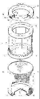
Fig. 1 shows a perspective view of the filter element
according to the invention in a disassembled state, whe-
rein portions of the composing parts are cut away for
clarity and
fig. 2 shows a filter element according to the inven-
tion in the assembled state and mounted in the housing of
an oil filter.
With reference to fig. 1 the filter element shown
therein is composed of a filter body 1, a metallic annular
cap 2, a metallic bottom cap 3 and a metallic perforate
supporting tube 4.
The cylindrical filter body is formed in a well-known
manner of a pleated filtering fabric which is often produ-
ced as a laminate; the filter body is embedded with its
zig-zag extending terminal edges 5 in rings 6 which are
formed e.g. of a visco-elastic polyurethane or a similar

CA 02237959 1998-OS-15
WO 97/21480 PCT/NL96/00453
4
suitable elastomeric material.
The step of embedding the terminal edges 5 may be
carried out while the rings 6 are still in a soft state in
a mould. Preformed rings 6, provided with an annular
groove for receiving the terminal edges 5 to be embedded,
may also be used. In that case, after the respective
terminal edges 5 being received in such grooves, the
grooves are filled up with a suitable filling material.
The metallic end cap 2 has a U-shaped cross-section,
as seen in the axial direction and thus conf fines an annu
lar space for receiving a ring 6 that makes part of the
filter body 1. The outer and inner circumferential walls
of the annular receiving space are indicated at 7 and 8
respectively. At a few circumferentialiy spaced locations
of the outer peripheral wall 7 a slot 9 is provided, which
makes part of a bayonet catch to be described below. This
slot has a portion 9a that extends, from the free terminal
edge 7a, at first in the axial direction and then turns to
a circumferentially sloping slot portion 9b which in turn
ends up into a holding seat 9c.
Similarly the metallic bottom cap 3 has an annular
space confined by an outer circumferential wall 10 and an
inner circumferential wall 11 for receiving a ring 3
making part of the filter body 1.
In the example shown in the drawing the supporting
tube 4 has its lower edge portion welded or riveted to the
outer circumferential wall 11 of the bottom cap 3.
A plurality of pin-shaped projections 12 is provided
adjacent the upper terminal edge of the supporting tube 4,
each of these projections being adapted to cooperate with
a slot 9 in the metallic end cap 2 in the manner of a
bayonet catch.
When assembling the filter element from the parts
shown in the drawing, the filter body 1 is inserted into
the supporting tube 4, so that the filter body will be
supported with its lower sealing ring 3 onto the bottom
surface of the annular deepened receiving space of the

CA 02237959 1998-OS-15
WO 97/21480 PCTlNL96/00453
bottom cap 3. In this stage the upper sealing ring 6
projects with its upper end face slightly beyond the upper
edge of the supporting tube 4. The end cap 2 is then
placed over the upper sealing ring 6 and the upper edge
of
S the supporting tube 4 in a position which will allow the
pin-shaped projections 12 to enter into the axial slot
portions 9a. The pin-shaped projections 12 having thus
entered into engagement with the slots 9, the end cap 2
is
turned in the arrow direction shown in the drawing, to
cause the pin-shaped projections 12 to move into the
sloping slot portions 9b and thereby pull the end cap 2
in
the axial direction. In this way an axially directed
clamping force will be exerted, due to which the two
sealing rings 6 will become with their end faces in sea-
ling contact with the bottom faces of the annular recei-
ving spaces in the end cap 2 and the bottom cap 3 respec-
tively.
The finished filter element may then be placed in a
well-known manner into a filter housing 21 as shown in
fig. 2. The filter housing 21 has an oil inlet 22 and an
oil outlet 23. In the connecting area between the inlet
and outlet a pressure ring 24 is sealingly pressed onto
a
seat within the housing, due to the spring pressure exer-
ted by a cover 25. The pressure ring 24 is provided with
a
gasket 26 for sealing engagement with the end gap 24 of
the filter element. The filter element is sealingly pres-
sed against the gasket 26 by means of a coil spring 27
provided around the free end of a rod 28 that is carried
by the pressure ring 24 and sealingly extends through a
central opening to be made in the bottom cap 3.
In the example shown in the drawing, in which the
supporting tube 4 is provided on the outer side of the
filter body, the fluid to be filtered will enter through
the central opening of the end cap 2 and flow outwardly
through the filter body. The supporting tube, however,
could also be placed within the filter body in which case
the fluid to be filtered would flow in the opposite direc-

CA 02237959 1998-OS-15
WO 97/21480 PCT/NL96/00453
6
tion, while the inlet and outlet of the filter housing
would change.

Representative Drawing
A single figure which represents the drawing illustrating the invention.
Administrative Status

2024-08-01:As part of the Next Generation Patents (NGP) transition, the Canadian Patents Database (CPD) now contains a more detailed Event History, which replicates the Event Log of our new back-office solution.

Please note that "Inactive:" events refers to events no longer in use in our new back-office solution.

For a clearer understanding of the status of the application/patent presented on this page, the site Disclaimer , as well as the definitions for Patent , Event History , Maintenance Fee  and Payment History  should be consulted.

Event History

Description Date
Inactive: Expired (new Act pat) 2016-11-15
Inactive: IPC from MCD 2006-03-12
Grant by Issuance 2004-12-14
Inactive: Cover page published 2004-12-13
Inactive: Final fee received 2004-09-29
Pre-grant 2004-09-29
Notice of Allowance is Issued 2004-04-14
Letter Sent 2004-04-14
Notice of Allowance is Issued 2004-04-14
Inactive: Approved for allowance (AFA) 2004-03-25
Amendment Received - Voluntary Amendment 2004-02-11
Inactive: IPC assigned 2003-08-22
Inactive: S.30(2) Rules - Examiner requisition 2003-08-11
Amendment Received - Voluntary Amendment 2001-04-26
Amendment Received - Voluntary Amendment 2001-03-30
Letter Sent 2001-02-26
All Requirements for Examination Determined Compliant 2001-01-31
Request for Examination Requirements Determined Compliant 2001-01-31
Request for Examination Received 2001-01-31
Inactive: First IPC assigned 1998-09-10
Inactive: IPC assigned 1998-09-10
Classification Modified 1998-09-10
Inactive: Notice - National entry - No RFE 1998-07-31
Application Received - PCT 1998-07-29
Application Published (Open to Public Inspection) 1997-06-19

Abandonment History

There is no abandonment history.

Maintenance Fee

The last payment was received on 2004-09-22

Note : If the full payment has not been received on or before the date indicated, a further fee may be required which may be one of the following

  • the reinstatement fee;
  • the late payment fee; or
  • additional fee to reverse deemed expiry.

Patent fees are adjusted on the 1st of January every year. The amounts above are the current amounts if received by December 31 of the current year.
Please refer to the CIPO Patent Fees web page to see all current fee amounts.

Owners on Record

Note: Records showing the ownership history in alphabetical order.

Current Owners on Record
FAIREY ARLON B.V.
Past Owners on Record
ANTONIUS JOSEPHUS BARTELS
Past Owners that do not appear in the "Owners on Record" listing will appear in other documentation within the application.
Documents

To view selected files, please enter reCAPTCHA code :


To view images, click a link in the Document Description column. To download the documents, select one or more checkboxes in the first column and then click the "Download Selected in PDF format (Zip Archive)" or the "Download Selected as Single PDF" button.

List of published and non-published patent-specific documents on the CPD .

If you have any difficulty accessing content, you can call the Client Service Centre at 1-866-997-1936 or send them an e-mail at CIPO Client Service Centre.


Document
Description 
Date
(yyyy-mm-dd) 
Number of pages   Size of Image (KB) 
Representative drawing 1998-09-13 1 13
Description 1998-05-14 6 258
Abstract 1998-05-14 1 53
Claims 1998-05-14 2 59
Drawings 1998-05-14 2 62
Claims 2001-03-29 2 58
Description 2004-02-10 6 255
Claims 2004-02-10 2 52
Representative drawing 2004-11-15 1 13
Reminder of maintenance fee due 1998-07-29 1 115
Notice of National Entry 1998-07-30 1 209
Courtesy - Certificate of registration (related document(s)) 1998-07-30 1 140
Acknowledgement of Request for Examination 2001-02-25 1 179
Commissioner's Notice - Application Found Allowable 2004-04-13 1 161
PCT 1998-05-14 9 321
Fees 2003-10-29 1 31
Fees 1999-11-11 1 49
Fees 2001-09-10 1 35
Fees 2000-09-12 1 60
Fees 2002-09-23 1 30
Fees 1998-10-19 1 52
Correspondence 2004-09-28 1 22
Fees 2004-09-21 1 28
Fees 2005-09-26 1 26
Fees 2006-09-10 1 28
Fees 2007-11-08 1 28
Fees 2008-10-09 1 34
Fees 2009-10-08 1 34
Fees 2010-10-05 1 38