Language selection

Search

Patent 2238402 Summary

Third-party information liability

Some of the information on this Web page has been provided by external sources. The Government of Canada is not responsible for the accuracy, reliability or currency of the information supplied by external sources. Users wishing to rely upon this information should consult directly with the source of the information. Content provided by external sources is not subject to official languages, privacy and accessibility requirements.

Claims and Abstract availability

Any discrepancies in the text and image of the Claims and Abstract are due to differing posting times. Text of the Claims and Abstract are posted:

  • At the time the application is open to public inspection;
  • At the time of issue of the patent (grant).
(12) Patent Application: (11) CA 2238402
(54) English Title: MULTI-POSITION GUIDE BAR FASTENING
(54) French Title: FIXATION DE GLISSIERE DE GUIDAGE A POSITIONS MULTIPLES
Status: Deemed Abandoned and Beyond the Period of Reinstatement - Pending Response to Notice of Disregarded Communication
Bibliographic Data
(51) International Patent Classification (IPC):
  • B27B 17/02 (2006.01)
  • B27B 17/08 (2006.01)
(72) Inventors :
  • LEINI, ARVO (Sweden)
  • SUNDSTROM, ERIK (Sweden)
(73) Owners :
  • KAPMAN AB
(71) Applicants :
  • KAPMAN AB (Sweden)
(74) Agent: GOWLING WLG (CANADA) LLP
(74) Associate agent:
(45) Issued:
(86) PCT Filing Date: 1996-11-14
(87) Open to Public Inspection: 1997-06-05
Availability of licence: N/A
Dedicated to the Public: N/A
(25) Language of filing: English

Patent Cooperation Treaty (PCT): Yes
(86) PCT Filing Number: PCT/SE1996/001471
(87) International Publication Number: SE1996001471
(85) National Entry: 1998-05-22

(30) Application Priority Data:
Application No. Country/Territory Date
9504238-8 (Sweden) 1995-11-28

Abstracts

English Abstract


Clamping device for mounting a chain saw guide bar to two threaded bolts
protruding from a chain saw machine unit with the guide bar center line
parallel to but offset from a line through the bolts, where the guide bar is
made with a slot (14) with a width substantially larger than the bolt
diameter, and with one or more inserts (17) in the slot, said inserts having
holes fitting the bolts and being locatable in a position where the holes are
offset from the center line (16) of the slot.


French Abstract

Cette invention concerne un dispositif de serrage permettant de monter la glissière de guidage d'une tronçonneuse sur deux boulons filetés qui dépassent du corps d'une machine de type tronçonneuse, ceci de sorte que la ligne centrale de la glissière de guidage soit parallèle mais décalée par rapport à une ligne passant par lesdits boulons. La glissière de guidage comporte une fente (14) dont la largeur est sensiblement plus grande que le diamètre des boulons, ainsi qu'un ou plusieurs inserts (17) qui sont situés dans la fente. Ces inserts comportent des trous s'adaptant aux boulons, et peuvent être placés en une position telle que les trous soient décalés par rapport à la ligne centrale (16) de la fente.

Claims

Note: Claims are shown in the official language in which they were submitted.

Claims
1. Clamping device for mounting a chain saw guide bar to two threaded bolts (18)protruding from a chain saw machine unit with the guide bar center line parallel to but
offset from a line through the bolts, characterized by the guide bar having a longitudinal
slot (14) with a width substantially larger than the bolt diameter and with at least one
insert (17) being located in the slit, said insert having the same width as the slot (14) and
at least one hole (21,22) fitting a bolt, said insert being locatable in at least one position
where the holes are offset from the center line (16) of the slot.
2. Clamping device according to claim 1, characterized by the insert being locatable in
another position where the holes are on the center line (16) of the slot.
3. Clamping device according to claim 1 or 2, characterized by the slot (14) being
symmetrically located in the guide bar.
4. Clamping device according to claim 1 or 2, characterized by there being two square
inserts (17) in the slot, each insert having one off-center hole located closer to one side.
5. Clamping device according to claim 1 or 2, characterized by there being one insert
(17) in the slot, said insert having four holes (21,22).
6. Clamping device according to claim 5, characterized by two holes (22) being located
on the center line (16) of the insert, and two holes (21) offset from the center line.
7. Clamping device according to claim 6, characterized by the insert (17) being integral
with a clamping plate (20) which is wider than the slot (14).

Description

Note: Descriptions are shown in the official language in which they were submitted.


CA 02238402 l998-0~-22
W O 97/19794 PCT/SE96/01471
- Mnlti-position ~uide bar ra~
round
Chain saw guide bars are normally attached to the mRf lline unit of a chain saw by two
5 threaded bolts pencl~ g a lon~it~l-lin~l slot through the rear end of the guide bar,
clefinin~. the direction of the guide bar, but allowing a longitudinal displ~cP.ment which is
needed when replacing a saw chain or compçn~qting for wear of the chain.
Comrnonly, the guide bar is symmetric with the slot symmetrically located on the center
10 line, m~king it possible to turn the guide bar over to wear both sides of the bar equally.
Behind the guide bar is a drive shaft with a drive sprocket for the chain.The bolts are
often located to let the bar center line pass through the drive shaft, as in the patents US
3,683,980 and US 3,955,279, but it is also knowm to let the center line pass below the
shaft as in patents US 2,845,967, US 2,910,100 and US 3,059,491 to allow a larger
15 deflection of the slack upper part of the chain. With introduction of self-tensioning drive
sprockets as shown in patent DE 41 37 4009 or SE 469 515 it has also been suggested to
let the bar c~.nt~rline pass above the drive shaft.
The present invention is a mounting arrangement for chain saw guide bars, allowing the
20 bar center line to pass above, straight through or below the drive shaft according to the
service conditions.
Description of the invention
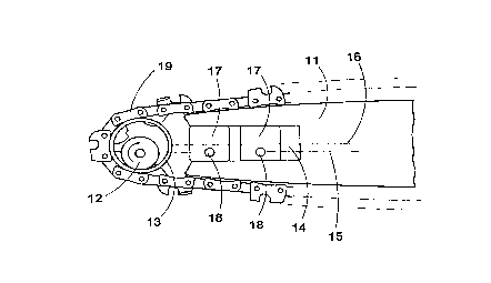
The invention is described with reference to the figures, where figure I shows a guide bar
25 mounted with the center line above the drive shaft, and figures 2 - 4 show different
embodyments of slot inserts according to the invention.
A saw chain (19) is driven by a drive sprocket ~12) on a drive shaft to travel around a
guide bar (l l ). The drive sprocket carries an outer drive ring (13) the center of which will
30 occupy an equilibrium position above the drive shaft when sawing. The saw m:~chine unit
is provided with two bolts (18), and the line (15) through the bolts passes also through

CA 02238402 l99X-0~-22
W O 97/19794 PCT/SE96/01471
the shaft of the drive sprocket (12). To make the chain pass smoothly from the drive ring
(13) to the upper side ofthe guide bar (11) the bar center line (16) h~ been displaced
upwards relative to the line (15) through the bolts (18). To accomplish this, the guide bar
is made with a slot (14) which is substantially wider than the bolt (18) diameter. The slot
is preferably symrnetrically located on the bar to allow reversing of the bar when worn.
In the slot (14) are placed one or more inserts (17) with holes to receive the bolts ~18).
The inserts can either be turned in different directions, or have several holes differently
located in relation to the center line (16) ofthe slot. In figure 1 the inserts (17) are turned
with the holes for the bolts (18) below the slot center line. Figure 2 shows how such
square inserts can be tunled into at least three positions with the holes below, above or on
the center line ( 16).
Figure 3 shows an insert with four holes, two of which (22) on the center line (16) and
two (21) offset from the center line. By reversing the insert, teh offset holes (21) can be
located below or above the center line. If the space is very restricted, the holes may touch
or slightly intersect each other.
Traditionally the guide bar is ;ltt~rh~(l to the m~rl~ine unit by fitting a clarnping plate
with two bolt holes outside the guide bar. The clarnping plate is wider than the slot (14)
and with one nut on each bolt the cl~nnping plate and the guide bar are fastened to the
m~ .hin~ unit. If one wishes to use such an existing clamping plate because it is part of or
coacts with the m~hine cover, the inserts should have a thickness not e~ee~ing the
guide bar ( 1 1 ) thickness.
In certain cases such as when mounting a guide bar on a vehicle-born chain saw, the
clatnping plate may have functions related to the guide bar geometry, such as
connectm~t~hing certain liquid supply channels, or providing an auxiliary chain guide. In
such cases the clarnping plate position relative to the bar should be retained, and the
clarnping plate should have four holes and could be made integral with a four hole
(21,22) insert as shown in figure 4. To ensure stiff clamping, the insert should have a
thickness not exceeding the bar thickness.

Representative Drawing
A single figure which represents the drawing illustrating the invention.
Administrative Status

2024-08-01:As part of the Next Generation Patents (NGP) transition, the Canadian Patents Database (CPD) now contains a more detailed Event History, which replicates the Event Log of our new back-office solution.

Please note that "Inactive:" events refers to events no longer in use in our new back-office solution.

For a clearer understanding of the status of the application/patent presented on this page, the site Disclaimer , as well as the definitions for Patent , Event History , Maintenance Fee  and Payment History  should be consulted.

Event History

Description Date
Inactive: IPC from MCD 2006-03-12
Application Not Reinstated by Deadline 2002-11-14
Time Limit for Reversal Expired 2002-11-14
Inactive: Abandon-RFE+Late fee unpaid-Correspondence sent 2001-11-14
Deemed Abandoned - Failure to Respond to Maintenance Fee Notice 2001-11-14
Letter Sent 1999-11-04
Inactive: Multiple transfers 1999-10-18
Classification Modified 1998-08-25
Inactive: First IPC assigned 1998-08-25
Inactive: IPC assigned 1998-08-25
Inactive: Notice - National entry - No RFE 1998-08-06
Application Received - PCT 1998-08-03
Application Published (Open to Public Inspection) 1997-06-05

Abandonment History

Abandonment Date Reason Reinstatement Date
2001-11-14

Maintenance Fee

The last payment was received on 2000-10-20

Note : If the full payment has not been received on or before the date indicated, a further fee may be required which may be one of the following

  • the reinstatement fee;
  • the late payment fee; or
  • additional fee to reverse deemed expiry.

Patent fees are adjusted on the 1st of January every year. The amounts above are the current amounts if received by December 31 of the current year.
Please refer to the CIPO Patent Fees web page to see all current fee amounts.

Fee History

Fee Type Anniversary Year Due Date Paid Date
Basic national fee - standard 1998-05-22
Registration of a document 1998-05-22
MF (application, 2nd anniv.) - standard 02 1998-11-16 1998-10-16
Registration of a document 1999-10-18
MF (application, 3rd anniv.) - standard 03 1999-11-15 1999-10-20
MF (application, 4th anniv.) - standard 04 2000-11-14 2000-10-20
Owners on Record

Note: Records showing the ownership history in alphabetical order.

Current Owners on Record
KAPMAN AB
Past Owners on Record
ARVO LEINI
ERIK SUNDSTROM
Past Owners that do not appear in the "Owners on Record" listing will appear in other documentation within the application.
Documents

To view selected files, please enter reCAPTCHA code :


To view images, click a link in the Document Description column. To download the documents, select one or more checkboxes in the first column and then click the "Download Selected in PDF format (Zip Archive)" or the "Download Selected as Single PDF" button.

List of published and non-published patent-specific documents on the CPD .

If you have any difficulty accessing content, you can call the Client Service Centre at 1-866-997-1936 or send them an e-mail at CIPO Client Service Centre.


Document
Description 
Date
(yyyy-mm-dd) 
Number of pages   Size of Image (KB) 
Representative drawing 1998-08-26 1 7
Abstract 1998-05-21 1 43
Description 1998-05-21 2 100
Claims 1998-05-21 1 37
Drawings 1998-05-21 1 22
Reminder of maintenance fee due 1998-08-03 1 115
Notice of National Entry 1998-08-05 1 209
Courtesy - Certificate of registration (related document(s)) 1998-08-05 1 140
Reminder - Request for Examination 2001-07-16 1 118
Courtesy - Abandonment Letter (Maintenance Fee) 2001-12-11 1 183
Courtesy - Abandonment Letter (Request for Examination) 2001-12-26 1 172
PCT 1998-05-21 7 240