Note: Descriptions are shown in the official language in which they were submitted.
CA 02238469 1998-OS-25
LOAD STRUT FOR A VARIABLE GEOMETRY NOZZLE
TECHNICAL FIELD
The invention relates to gas turbine engines and in particular to a load strut
for
divergent master petal of variable geometry nozzles.
BACKGROUND OF THE INVENTION
Gas turbine engines for aircraft achieve thrust by discharging hot gas through
the
exhaust nozzle.
A variable area convergent/divergent nozzle is necessary in order to achieve a
good
efficiency for mufti-mission application. The maximum efficiency is obtained
with an
independent control of exhaust nozzle throat and exit areas. With this the
maximum
expansion of the gases and therefore maximum thrust is achieved at all times.
One of the goals of the designers is to increase the aircraft manoeuvrability,
moreover
in those flight points in those the aerodynamic control surfaces begin to lose
their
efficiency. A way of achieving this goal is by vectored the gas from the axial
direction to
achieve a thrust component which is up, down or sideways. At present there are
several
solutions with two-dimensional convergent/divergent nozzles as that disclosed
in U.S..
4,763,840. But these nozzles can only orient the gas in one direction
(generally pith)
and they are heavier than the axisymmetric convergent/divergent nozzles.
There are different systems of 3-D thrust vectoring convergent/divergent
nozzles. All
these systems can be classified into three major groups:
- Those that orientate the whole exhaust nozzle upstream of the convergent
section.
Due to the fact that the alteration of the geometry is done upstream of the
throat,
perturbations are induced in the turbine, Moreover, highly complicated sealing
device is
required.
- Those that orientate the flow at the outlet itself of the exhaust nozzle
more
downstream of this. With this system there is an efficiency reduction and the
weight
increases due to this system requires a additional device.
- Those that orientate the divergent segment of the exhaust nozzle. With this
system
the perturbation upstream of the turbine is minimized. The increase in weight
is less than
in the previous case, by the fact that the nozzle itself orientates the flow
without the
help of any other additional device.
Within this third group, the most common embodiment includes, as shown in US
Pat.
5,082,182. a convergent section, that consists of a plurality of master petals
and a
t>i~r:.i;ty of sia~~e petals in order to provide an ad::qua~.e scaling. The
throat area is
governed by the well known mechanism of cams roller or other mechanism as
perimetral
mechanism. The control of the throat area requires a number of linear
actuators.
Downstream of this convergent section there is a divergent section consisting
of the
same plurality of divergent master petals and a plurality of slave petals in
order to
provide an adequate sealing. The divergent master petals are connected to
convergent
CA 02238469 1998-OS-25
- 2 -
master petals by universal linkage. The linkage permits the lateral and radial
motion of
the divergent master petals allowing the flow orientation.
The divergent master petals are linked to an external ring by load struts. The
connection of the strut to the divergent master petal is carried out via a
spherical
linkage, while the connection to the external ring is made via a cylindrical
linkage.
Both outlet area and flow orientation is controlled by the external ring. This
external
ring requires at least three linear actuators.
With this embodiment two independent actuator systems are required, internal
and
external.
Another variable geometry nozzle is disclosed in EP 055722981, characterized
by fact
that it controls the throat area, outlet area and flow orientation only with a
set of linear
actuators. That supposes a reduction in cost and a more simple design of the
actuator
system.
This single system consists of three rings, concentric among themselves and
with the
axis of the turbine, and having a plurality of linear actuator linked by their
upstream end
to the structure of the turbine.
The rings mentioned above are connected together and to the structure of the
turbine
via linkage elements and guide devices which allow the joint axial
displacement of the
three rings in equal magnitude, with respect to the structure of the turbine,
as well as a
relative rotary movement of the intermediate and external rings between
themselves and
with respect to the internal ring, thereby allowing the external ring to be
inclined in any
direction with the centre of rotation in the axis of the turbine.
The convergent master petals are connected at a point in their upstream
segment to
the internal ring by cylindrical linkages, tangencial to a theoretical
circumference witch
is concentric to the longitudinal axis of the engine and located in a
theoretical plane
perpendicular to such longitudinal axis.
The master petals of the divergent section are subdivided transversely into at
least two
segments that are connected to each other by a cylindrical linkage
perpendicular to that
of a linkage between the master petal of the convergent an divergent sections.
The
divergent master petals are connected at a point in their upstream segment to
the master
convergent petals by cylindrical linkages, parallel to the linkage between the
internal
ring and the master convergent petals. The downstream segment is connected to
the
external ring via a load strut that links to that segment by a spherical
linkage and to the
external ring by a cylindrical linkages, tangencial to a theoretical
circumference witch is
concentric to the longitudinal axis of the engine and located in a theoretical
plane
perpendicular to such longitudinal axis. The invention is related to said load
strut.
The external ring is connected to downstream ends of the linear actuators by
spherical
linkages. The external ring is divided in two half ring that are connected to
each other
by a cylindrical linkage, perpendicular to the theoretical axis of the engine.
The linkage
half rings mentioned allow a relative rotary movement of the external half
rings between
themselves achieving the outlet control or allowing the external ring to be
inclined in
CA 02238469 2005-09-12
any direction with the centre of rotation in the axis of the turbine as an
unique ring,
orienting the flow in any direction.
In patent EP 055722981 the master petals are distributed in a way that half of
them
are connected to one of the two external half ring via a load strut, an the
other half are
connected to the other external half ring.
The distribution said above limits outlet are control due to petal
interferences and
sealing problems. If two of the master petals are located in the linkage
between the
two external half ring the limitation of outlet are control is smaller.
This new distribution of the petals needs a different load strut. The new load
strut
must allow that the said divergent master petals are connected to the both
external half
rings at the same time.
SUMMARY OF THE INVENTION
In accordance with one aspect of the present invention, there is provided a
load strut
for a divergent master petal of variable geometry nozzles of gas turbine
engines, the
strut being located in linkage between two external half rings which form an
external
ring; wherein the strut is linked to both the external half rings and the
master
divergent petal.
An object of an aspect of the present invention is to provide a load strut
that allows to
connect a divergent master petal to both external half rings at the same time.
If the two external half rings move as a unique external ring, the load strut
has to work
in the same way as a load strut that connects a divergent master petal to a
single
external ring.
If there is a relative rotary movement between both external half rings, the
theoretical
symmetric plane of the load strut has to be the same that the bisector plane
form by
the two external half rings remaining the linkage with the divergent master
petal in
said plane.
Accordingly, the device in accordance with an aspect of the present invention
comprises two bars that are connected to each other at a point downstream by a
cylindrical linkage. Each bar is connected at a point upstream by a spherical
or
universal linkage to a external half ring.
The relative position of the both bars is fixed by the linkages and the
position of the
external half rings, forming a united. This united has an only degree of
freedom,
equally the other conventional load struts. Said degree of freedom is the
rotation
about the axis formed by the theoretical line through the said two spherical
or
universal linkages.
In order to joint the two bars to the master divergent petal a transition part
is
necessary. This part is connected by a cylindrical linkage to each bar. These
linkage
are sensibly parallel to the linkage between the mentioned bars. The three
cylindrical
CA 02238469 2005-09-12
3a
linkage have to be sensibly coplanar. In such form, when there is a relative
motion
between both external half ring, there is a relative motion between both bars
and then
the distance between both cylindrical linkages of the transition part changes
slightly.
Due to the alignment of the three cylindrical linkages, the mentioned
variation is
function of (1-cos) of the rotation angle, being this angle very small. The
cylindrical
linkage clearances allow this slight variation of the distance.
The load strut that is the object of the invention comprises the two bars and
the
transition part. The linkage between the load strut and the divergent master
petal can
be the same as a conventional load strut.
CA 02238469 1998-OS-25
_. _ 4
BRIEF DESCRIPTION OF THE DRAWINGS
Figure 1 is a perspective of a exhaust nozzle related with the invention.
Figure 2 is a perspective of a detail of the nozzle when the load strut
related with the
invention appears.
Figure 3 is an exploded perspective showing the load strut related with the
invention.
Figure 4 is a view showing sealing problems in a nozzle in accordance with the
patent
EP 055722981.
Figure 5 is a view showing that there isn't sealing problems in a nozzle in
accordance
with the patent EP 055722981 using the load strut of the invention.
Figure 6 is a view showing a nozzle in accordance with the patent EP 055722981
using the load strut of the invention orienting the flow.
DESCRIPTION OF THE PREFERRED E~~IBODIMENT
Figure 1 represents, in a diagrammatic and partially cross-sectional
perspective view, a
exhaust nozzle that has a load strut 1 in accordance with the invention, with
arrow 33
showing the direction of the flow. As with traditional exhaust nozzle, the
nozzle
represented in figure 1 includes a casing 2, a convergent section 3 and a
divergent
section 4. The convergent section 3 consists of a plurality of convergent
master petals 5
and convergent slave petals 34. In the same way, the divergent section 4
consists of a
plurality of divergent master petals 6 and divergent slave petals 31.
The variation in the throat area, defined by the downstream end contour of the
convergent petals, the outlet area, defined by the downstream end contour of
the
divergent petals, and the vectoring of the thrust are controlled by a system
consisting of
three rings 7,8,9, concentric with eachother and with the axis of the turbine.
The
external ring 9 is divided in two external half ring. Only one of the two
external half ring
is represented in figure I. The position of the rings 7,8.9 is controlled by a
plurality of
linear actuators 10 which are linked by their upstream ends to the casing 2.
If the
vectoring of the thrust is not required the intermediate ring 8 can be
removed.
The rings 7,8,9 are also linked to each other by devices that allow axial
displacement
of the set of three rings, in equal magnitude, with respect to the casing 2 of
the turbine,
as well as a relative rotary movement of the intermediate ring 8 and external
half ring 9
between themselves and with respect to the internal ring 7, in such way that
allows the
external half rings 9 to incline in any direction, and a relative rotatory
movement of the
external half rings 9 between themselves.
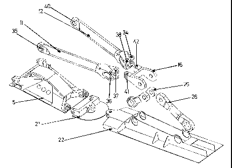
Figure 2 represents a perspective of a detail of the nozzle when the load
strat I related
with the invention is present. The load strut comprises two bars 11,12. Each
bar is
connected at its upstream end by a spherical or universal linkage I 3,14 to a
external half
ring and they are connected to each other its downstream end by a cylindrical
linkage
15, this cylindrical linkage 15 is perpendicular to a theoretical plane 32
that contains
both bars 11,12. The mentioned plane is formed by the centre of the spherical
linkages
13,14 and the cylindrical linkage 15. In such way, the relative position of
the both bars
CA 02238469 1998-OS-25
- 5 -
11,12 is fixed by the linkages 13,14,15 and the position of the external half
rings 9,
forming a united. This united has an only degree of freedom, equally the other
conventional load struts 19. Said degree of freedom is the potation about the
axis
formed by the theoretical line through the said two spherical or universal
linkages 13,14.
The transition part 16 is connected by a cylindrical linkage 17,18 to each bar
11,12.
These linkage 17,18 are sensibly parallel to the linkage 15. The three
cylindrical linkage
15,17,18 have to be sensibly coplanar. The linkage between the transition part
16 and
the divergent master petal can be the same as a conventional load strut 19.
The convergent master petals 5 are connected at a point upstream to the
internal ring
7 by cylindrical linkages 20 , tangencial to a theoretical circumference witch
is
concentric to the longitudinal axis of the engine and located in a theoretical
plane
perpendicular to such longitudinal axis.
The master divergent petals 6 are subdivided transversely into at least two
segments.
The upstream segment 21 is connected at a point in their upstream segment to
the
master convergent petals by cylindrical linkages 23 , tangencial to a
theoretical
circumference witch is concentric to the longitudinal axis of the engine and
located in a
theoretical plane perpendicular to such longitudinal axis. The downstream
segment 22 is
connected to the upstream segment 21 by a cylindrical linkage 24 perpendicular
to the
master divergent base.
The divergent master petal 6 is connected to the load strut 1 or 19 by two
intermediate
bars 25,26. These intermediate bars 25,26 are connected to the divergent
master petal 6
by spherical linkages 27,28. The intermediate bar located downstream 26 is
connected
to the load strut 1 or 19 by a spherical linkage 29 and he intermediate bar
located
upstream 25 is connected to the load strut 1 or 19 by a cylindrical linkage
30.
Figure 3 is an exploded perspective showing the load strut related with the
invention.
The invention comprises two bars 11,12 and a transition part 16.
Bar 11 has at one end a lug 35, that is designed to receive a spherical
linkage 13. That
linkage joints the said bar 11 with one external half ring 9a. The other end
has two lugs
36,37. One of the lugs 37 is connected to the lug 38 of the other bar 12 by a
cylindrical
linkage 15. In the same way, the other bar has at one end a lug 40, that is
designed to
receive a spherical linkage 14. That linkage joints the said bar 12 with the
other external
half ring 9b.
The other lug 36 of the bar 11 is connected to the lug 41 of the transition
part 16 by a
cylindrical linkage 17. In the same way, the other lug 39 of the bar 12 is
connected to
the lug 42 of the transition part 16 by a cylindrical linkage 18.
The design of the bars I I ,12 could be made in such way that both bars would
be
equal. Therewith it is possible to reduce cost of design, manufacturing and
maintenance.
Figure 4 shows a relative rotation between both external half ring 9 in
accordance with
the patent EP 0557229B 1. The divergent master pets! 6a rotates clockwise and
the
divergent master petal 6b rotates counter-clockwise. These rotations cause big
gap
CA 02238469 1998-OS-25
- 6 -
between the divergent master petals 6a,6b that the divergent slave petal 31
has to cover.
With a small angle of rotation the gap is to big and there is a sealing
problem.
Figure 5 shows the same rotation between both external half ring 9 as figure 4
in
accordance with the patent EP 055722981, but using the load strut 1 of the
invention.
In the same way as above, the divergent master petal 6a rotates clockwise and
the
divergent master petal 6b rotates counter-clockwise, but now there is other
divergent
master petal 6c that remaining at same position. Thence the gap between
divergent
master petals 6a,6b is distributed up two divergent slave petals 31a,31b
without sealing
problems. A bigger relative rotation between both external half rings 9a.9b is
necessary
to produce sealing problems. The variation range of the nozzle outlet area is
bigger due
to a bigger allowable relative rotation between both external half ring 9
When there is a relative motion between both external half ring 9, there is a
relative
motion between both bars 11,12 and then the distance between both cylindrical
linkages
17,18 of the transition part 16 changes slightly. But, the cylindrical linkage
clearances
allow this slight variation of the distance.
Figure 6 shows the rotation of both external half ring 9 together relative to
the
internal ring 7. In such case, there isn't a relative motion between both
external half ring
9 and hence between both load strut bars 11,12. Then the load strut 1 works as
a
conventional load strut 19.