Note: Descriptions are shown in the official language in which they were submitted.
CA 02238~0~ 1998-0~-2~
WO 98116089 1~ 84o3
OIL WELL HEATER CABIE
Technical Field
This invention relates in general to electrical cable
and in particular to cable for transferring heat to oil
5 well tubing.
Background Art
This invention provides a method and apparatus for
heating wellbores in cold climates through the use of an
improved electrical heater cable. More particularly, but
10 not by way of limitation, this invention relates to a
method and apparatus for placing within a wellbore an
electrical cable along the production tubing for
maintaining adequate temperatures within the wellbore to
maintain adequate flow characteristics of hydrocarbons
15 running from a reservoir to the surface.
The production of oil and gas reserves has taken the
industry to increasingly remote inland and offshore
locations where hydrocarbon production in extremely cold
climates is often required. Unique problems are
20 encountered in producing oil in very cold conditions. As
a result, production techniques in these remote and
extreme climates require creative solutions to problems
not usually encountered in traditionally warmer areas.
One problem often encountered in cold climate
25 hydrocarbon production has been finding ways to maintain
adequate hydrocarbon flow characteristics in the
production tubing. For example, under arctic conditions,
a deep permafrost layer surrounds the upper section of a
wellbore. This cold permafrost layer cools the
30 hydrocarbon production fluid as it moves up the production
CA 02238~0~ 1998-0~-2~
WO98/16089 2 PCT~S97/18403
tubing, causing hydrates to crystallize out of solution
and attach themselves to the inside of the tubing.
Paraffin and asphaltene can also deposit on the inside of
the tubing in like manner. As a result, the cross-section
5 of the tubing is reduced in many portions of the upper
section of the wellbore, thereby restricting and/or
choking off production flow from the well. Also, if water
is present in the production stream and production is
stopped for any reason such as a power failure, it can
10 freeze in place and block off the production tubing.
Wellbores having electrical submersible pumps
experience higher production pressures due to the above
restrictions, which accelerates wear of the pump and
reduces the run life of the system, causing production
15 costs to increase. Wells without downhole production
equipment also suffer from similar difficulties as
production rates fall due to deposition buildup. One
method of overcoming these problems is to place a heating
device of some sort adjacent to the production tubing to
20 mitigate fluid temperature loss through the cold section
of the well.
Presently, conventional heating of the production
tubing utilizes a specialized electrical heat trace cable
incorporating a conductive polymer which is attached to
25 the tubing. This polymer heat trace cable is designed to
be temperature sensitive with respect to resistance. The
temperature sensitive polymer encapsulates two electrical
conductors, and as the electrical current flows through
the polymer between the conductors it causes resistance
30 heating within the polymer, which ln turn raises its
CA 02238~0~ 1998-0~-2~
WO98/16089 PCT~S97/18403
temperature. As the temperature increases, the resistance
of the polymer increases and the system becomes self
regulating. However, this conventional approach to making
a heater cable for application in oil wells has several
5 severe limitations.
One primary disadvantage of heat trace cable with
conductive polymers is that these polymers can easily be
degraded in the hostile environment of an oil well. To
overcome this, several layers of expensive high
10 temperature protective layers have to be extruded over the
heat trace cable core. This increases the cost
substantially and makes the cables very difficult to
splice and repair. Another disadvantage of heat trace
cables of conventional conductive polymer design is that
15 the length of the cables is limited due to the decrease in
voltage on the conductors along the length. This requires
extra conductors to ~e run along the heat trace cable to
power additional sections of heat trace cable deeper in
the well. These extra conductors also require extra
20 protection with appropriate coverings, and they require
extra splices along the cable assembly. Splices also
reduce reliability of the system and the coverings add
even more cost.
Conventional electrical submersible pumps use a
25 three-phase power cable which has electrical insulated
conductors embedded within an elastomeric jacket and
wrapped in an outer armor. The insulation is fairly
thick, being typically in the range from .070 to .090
inch. One type, for hydrogen sulfide protection employs
30 extruded lead sheaths around the insulated conductors. An
CA 02238~0~ 1998-0~-2~-
WO9811~89 PCT~S97/184~3
elastomeric braid, tape or jacket separates the lead
sheaths ~rom the outer armor. These cables are used only
for power transmission, and would not transmit heat
efficiently to tubing because of the thick layer of
5 insulation, and because of the tape, braid, or jacket.
Therefore, there is a need for a method and cable for
heating production tubing in a reliable manner without
requiring expensive multi-layer protective coverings and
extra splices. In addition, this new cable should be
lO robust enough to be reused and be cost effective in its
construction and design.
Disclosure o~ Invention
The present invention provides a new and improved
heater cable and methods for applying the heater cable in
15 subsurface oil well applications. A heater cable with
~ heat generating conductors is disclosed wherein the
conductors are surrounded by a thin high-temperature
dielectric insulating material and are electrically joined
together at the end furthest from the power source. The
20 conductors are preferably made of copper or of other low
resistance conducting metal. A protective sheathing
encapsulates the dielectric material. The protective
sheathing is advantageously made of lead. The cable may
be made in a flat or round configuration and is completed
25 by armoring the conductor assembly with an overall wrap of
steel tape providing extra physical protection.
The heater cable may also optionally include
thermocouples and~or other sensors to monitor temperature
of the heater cable and/or other characteristics of the
30 surrounding environment. For example, temperature at
CA 02238~0~ 1998-0~-2~
WO9811~89 5 PCT~S97/18403
various points along the length of the cable may be
monitored and relayed to a microprocessor so as to adjust
the power source to the heater cable. Other instruments
also may be connected to the far end of the heater cable
5 to use the heater cable as a transmission means to carry
additional well performance data to a microprocessor.
In the preferred embodiment, a three-phase copper
conductor heater cable is disclosed. The low-resistance
heater cable may have more than one conductor size along
l0 its length to vary the amount o'f heat dissipated by the
cable in various sections of the well.
The heater cable in one major application is inserted
in a hydrocarbon wellbore and strapped to a production
tubing contained therein. The heater cable is provided in
15 the wellbore to deliver heat along the tubing in the
wellbore, thereby preventing build-up of hydrates, ice,
asphaltenes and paraffin wax or other heat sensitive
substances which may collect on the inner surface of the
production tubing, causing a restriction or obstruction to
20 production fluid flow.
Brief Description of Drawings
Figure l is a schematic sectional view illustrating a
well having a heater cable in accordance with this
invention.
Figure 2 is a an enlarged sectional view of the
heater cable of Figure l.
Detailed Description of the Invention
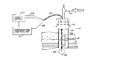
Figure l illustrates a well ll having one or more
strings of casing 13 extending through the well. A string
30 of production tubing 15 extends through casing 13 to the
CA 02238~0~ l998-0~-2~
WO98/1~89 PCT~S97/18403
surface. A wellhead 17 is located at the surface. A
flowline 19 extends from wellhead 17 for the transmission
of production fluids.
A heater cable 21 extends through wellhead 17 and
5 down the well along tubing 15. Straps 23 secure heater
cable 21 to tubing 15 at regular intervals. Heater cable
21 has three conductors 25 which are of a metal which is a
good electrical conductor. In one embodiment, conductors
25 are #6 AWG copper. The three conductors 25 are
10 electrically insulated from each other and are connected
at the surface to a power source 27, which supplies three-
phase electrical current down conductors 25. In the
preferred embodiment, power source 27 is a conventional
supply which supplies current at levels which can be
15 varied. The voltage supplied may be in the range from
about 150 to 500 volts, considerably lower than voltage
supplied by a power supply for an electrical submersible
pump, which may be 1000 to 2000 volts.
Optionally, a sensing wire 29 extends along the
20 length of heater cable 21 to a downhole transducer or
sensor (not shown). Sensing wire 29 comprises in the
embodiment shown a two conductor cable that leads to a
temperature controller 31. Temperature controller 31 is
preferably a microprocessor which controls power source 27
25 for regulating the amount of power supplied through
conductors 25. As shown schematically in Figure 1, the
lower ends of conductors 25 are directly connected
together at a common junction 33.
Referring to Figure 2, each conductor 25 is
30 surrounded by a dielectric layer which is in a good high
CA 02238~0~ 19s8-0~-2~
WO98/16089 ~ 7 PCT~S97/18403
temperature electrical insulation. In the embodiment
shown, the dielectric layer includes a polymer film or
tape 35, which is preferably a polyamide marketed under
the trademark Kapton. Alternately, the tape may be from a
5 group consisting of chlorotrifluoroethylene (CTFE),
fluorinated ethylene propylene (FEP),
polyterrafluoroethylene (PTFE), or polyvinylidine fluoride
(PVDF) or combinations thereof. Tape 35 is approximately
.0015 inch in thickness, and after wrapping provides a
10 layer of about .006 inch thickness.
The dielectric layer also has a polymer extrusion 37
which is extruded over tape 35. Extrusion 37 is also a
good high temperature electrical insulator and is
preferably an FEP marketed under the name Teflon.
15 Extrusion layer 37 is preferably about .010 inch in
thickness. The thermal conductivities of tape 35 and
extrusion 37 are poor, however being thin, do not
significantly impede the transfer of heat from conductors
25. ~or the preferred materials, the thermal conductivity
20 of tape 35 is .~55 watts per meter, degree kelvin, while
the thermal conductivitY of extrusion 37 is .195 watts per
meter, degree kelvin.
A protective metal sheath 39 is extruded over
extrusion 37 in physical contact with outer dielectric
25 layer 37. ProtectiVe sheath 39 is preferably of a
material which is a good thermal conductor yet provides
protection against damage to~the electrical insulation
layers 35, 37. Preferably, sheath 39 is of a lead or lead
alloy, such as lead and copper. The thickness of lead
30 sheath 39 is substantially greater than the thickness of
CA 02238~0~ 1998-0~-2~
WO9811~89 8 PCT~S97118403
the combined electrical insulation layers 35, 37. In the
preferred embodiment, the thickness of lead sheath 39 is
about .020 to .060 inch, preferably .050 inch. The range
of the combined thickness for the two layers 35, 37 is
5 about .0l0 inch to .025 inch. The thermal conductivity
of lead is about 34 watts per meter, degree kelvin. Other
metals that may be suitable for sheath 39 include steel
and its alloys or aluminum and its alloys.
Heater cable 21 in the preferred embodiment is of a
l0 flat type. That is, the insulated conductors 25 are
spaced side-by-side with their centerlines 41 located in a
single plane. It is desired to facilitate heat conduction
through lead sheaths 39. To enhance the heat conduction,
the lead sheaths 39 are in physical contact with each
15 other. Preferably lead sheaths 39 have a generally
rectangular configuration, having four flat sides 43 with
beveled corners 45. The flat sides 43 adjacent to each
other are abutted in physical contact. The lead sheath
39a on the middle conductor 25 has oppositely facing flat
20 sides 43 that abut one flat side 43 of each sheath 39b,
39c on the lateral sides.
In the embodiment shown, U-shaped liners 47 are
employed around lead sheaths 39 to resist deformation due
to the wrapping of an armor 49. Liners 47 are shown to be
25 long U-shaped strips of a conductive metal, such as steel,
which is harder than the lead alloy material of lead
sheaths 39. Liners 47 extend around the sides, tops, and
bottoms of the two lateral lead sheaths 39b, 39c and over
a portion of the middle lead sheath 39a. Alternately,
30 liners 47 may comprise a wrap of thin metal tape ~not
CA 02238~0~ l998-05-2~
WO98/16089 9 PCT~S97tl8403
shown). Also, liners 47 may not always be re~uired.
An outer armor 49 is wrapped around the subassem~ly
comprising liners 47, lead sheaths 39, and sensing cable
29. Armor 49 is a metal tape, preferably steel, that is
5 wrapped as in conventional electric power cable for
electrical submersible pumps. Armor 49 is a good heat
conductor, which is facilitated by metal-to-metal contact
with sheaths 39 through retainers 47.
In operation, three-phase power will be supplied to
10 the three conductors 25. Although conductors 25 are low
in resistance, heat is generated within conductors 25
because of high current flow. The heat passes through the
thin dielectric layer 35, 37 into the lead sheaths 39.
The heat transmits readily through the lead sheaths 39 and
15 out the armor 49 to tubing 15. The heat is transmitted to
tubing 15 to maintain a desired min;mllm temperature in
tubing 15.
A transducer (not shown) located on the lower end of
sensor wire 29 senses the temperature of tubing 15 and
20 applies a signal to temperature controller 31.
Temperature controller 31 adjusts the current supplied by
power supply 27 depending upon the desired temperature.
Well fluid flowing through tubing 15 is heated from
the tubing. The well fluid may be flowing as a result of
25 an electrical submersible pump (not shown) installed on
tubing 15, another type of artificial lift, or it may be
flowing due to internal formation pressure.
A substantial improvement of the present invention
over existing technology is that it operates at very low
30 voltage and high current. This results from the use of
CA 02238~0~ 1998-0~-2~
WO9~1~89 10 PCT~S97118403
low resistance materials such as copper as the heating
element. The low resistance allows high current flow at
low voltage, resulting in two advantages. First, low
voltage decreases electrical stress on the insulation
5 which increases the useful life of the cable. Secondly,
the cable can be made in very long lengths of lO,OOO ft.
or more without having to apply high voltage at the power
source.
Another advantage is that because the heat is
lO generated by current through the conductors, the rate of
heat generation is predictable along the cable throughout
its length. Furthermore, if more heat is desired in any
particular section of the installation, the diameter of
the conductors can be reduced in this area to create more
15 heat without adversely affecting the heat dissipation over
the rest of the cable.
Temperature sensing devices within or attached to the
cable can be used to monitor well conditions along the
production tubing and/or to control the temperature of the
20 cable by automatically adjusting the current supplied to
the cable to achieve a preset desired temperature.
Lastly, because in the preferred embodiment the
heater cable is a balanced three-phase system, the voltage
at the end of the cable farthest from the power source
25 where all three conductors are electrically joined
together is at or near zero potential voltage with respect
to earth. This provides easy access to attach other
instruments which can use the heater cable as a
transmission line to carry additional data about well
30 conditions to the surface.
CA 02238~0~ 1998-0~-2~
WO98/1~89 PCT~S97/18403
While the invention has been shown in only one of its
forms, it should be apparent to those skilled in the art
that it is not so limited but susceptible to various
changes without departing from the scope of the invention.
For example, rather than using three-phase power and
three conductors for the heater cable, direct current
power and two conductors could be employed.