Note: Descriptions are shown in the official language in which they were submitted.
CA 02238549 1998-OS-26
WO 97/22876 PCT/US96/19979
-1-
h
MULTICYCLE LOOP TNJECTION FOR TRACE ANALYSIS
BY ION CHROMATOGRAPHY APPARATUS AND METHOD
TECHNICAL FIEL-DD
The present invention relates, generally, to ion
chromatography, and more particularly, relates to trace
analysis by ion chromatography.
BACKGROUNDART
The use of high purity water (HPW) is becoming
increasingly important in a number of processes in the
power and semiconductor industries. For example, in
the power industries, HPW is employed as a coolant for
the reactor and/or driving fluid for the steam turbine
generators. Further, in the semiconductor industries,
HPW is used in many manufacturing processes.
In either industry, the presence of trace ion
contaminants in the high purity water indicates
problems associated with system performance. In the
power industries, the detection of trace ions in high
purity water is employed to monitor ion intrusion into
nuclear power plant secondary systems and corrosion.
In the semiconductor industries, the presence of trace
ion contaminants in the HPW can cause poor product
yields, such as logic errors, heat dissipation problems
and signal propagation problems with the semiconductor.
One method of detecting or measuring very low
concentrations or trace anion and canon contaminants
CA 02238549 1998-OS-26
WO 97/22876 PCT/US96/19979
-2-
is through ion chromatography (IC). This technique has
proved extremely useful and has been used in these
industries for over fifteen years. Ion chromatography
methods for the part per billion (ppb) and sub ppb .,
determination of ions in high purity water have
conventionally used concentrator columns. These ,
columns contain a small volume of ion exchange resin
with selectivity similar to the resin in the analytical
or separation column.
l0 A known quantity of high purity water sample is pumped
through concentrator column 10, as illustrated in
typical prior art system configuration 11 of FIGURE 1.
The concentrator column retains anions or cations of
interest from the HPW while allowing the remaining
water matrix to pass through the column.
After the desired sample volume has been concentrated
in the concentrator column 10, the concentrator column
is switched in-line (via, valve 12) with the eluent
from eluent source 13 and a separator column 14. The
separation then proceeds by the normal elution process .
While this technique has proven useful for monitoring
trace ionic contamination in HPW, several problems are
inherent with this system. For example, eliminating
pump flow rate perturbations when the concentrator
column is switched into the eluent flow. Further, it
is desirable that the sample pump 15, which transfers
the sample solution from sample source 16 through
concentrator column 10, provide a precise flow rate.
Such precision enables accurate quantitation since a
substantially known volume of sample will be passed
through the concentrator.
Any residual sample solution from the pump 15, and
hence, residual trace ionic contamination, will be
CA 02238549 1998-OS-26
WO 97/22876 PCT/US96/i9979
-3-
added to the sample or standards which will
significantly affect the results. Moreover, because
the level of this contamination may be variable, this
z contamination cannot be removed or factored out as a
fixed quantity. The employment of pumps with high
precision, however, is very expensive, especially
considering the fact that the eluent pumps also have
high flow rata precision.
Another problem associated with conventional
concentration sample pumps is in quantitation
calibration. Quantitation calibration is normally
performed by processing standards, which contain the
ions of interest at known concentrations, through the
concentrator column as described above. With proper
calibration and sampling, this technique allows for the
determination of trace ions down to the low ng/L (part-
per-trillion) level.
Since external calibration is required, standards at
the parts-per-trillion (PPT) level must be prepared.
It is generally not practical to routinely produce
accurate PPT level standards since the water used to
dilute the more concentrated standards may contain
trace ionic impurities at levels approaching the
desired standard level.
Solutions to some of the problems associated with
conventional IC methods used for trace ions in HPW have
been addressed in the prior art. Typical of these
patented inventions are disclosed in U.S. Patent No.
4,715,216 to Mueller; and U.S. Patent Nos. 4,991,428
and 5,042,293 to Heyde. Heyde describes an improved
method for quantitation calibration at the PPT level
which overcomes the problem of trace contamination from
the water used to prepare standards at very low
concentrations. Mueller on the other hand describes a
CA 02238549 1998-OS-26
WO 97/22876 PCTlUS96/19979
-4-
technique which overcomes the problem caused by the
drop in conductivity in the beginning of a chromatogram
when a concentrator column is used.
While these prior art assemblies have improved the
performance of ion chromatography for the analysis of
high purity water, the above-mentioned problems related
to the use of a sample pump for concentration still
exist.
As an alternative to conventional concentration, on-
column pre concentration may be employed as a means for
eliminating the need for a sample pump. In this
technique, a large sample loop, which may have a volume
as large as 10 mL (for a 4 mm diameter column), is
switched in-line or in fluid communication with the
separator column and an eluent source for direct
loading of the sample on the column by the eluent.
Accordingly, mixing of the sample solution with the
pumped eluent employed to sweep the sample solution
into the separator column must be minimized during the
column loading to avoid degrading the separation of the
early eluting components. Another problem associated
with on-column preconcentration is that while it is
desirable to employ a large volume sample loop, the
physical dimension of the loop may be limiting for
performance purposes. For example, a large volume
sample loop having a relatively large inner diameter
passage and a short length tends to be problematic when
subjected to the relatively higher pressures provided
by the eluent pump (i.e., 1000-3000 psi). As a result,
the tubing should have an internal diameter so that the
volume will be significant, but the length, and hence
pressure drop through the tubing, minimized. The wall
thickness of the tubing must allow for the high
pressure requirements.
CA 02238549 1998-OS-26
WO 97/22876 PCT/US96/19979
-5-
In contrast, tubing with a smaller interior diameter
will require an injection loop of greater length to
provide the proper sample volume. This arrangement may
,, be problematic in that the increased passage length of
the injection loop fosters susceptibility to bubble
formation and retention. These bubbles substantially
reduce volume reproducibility which adversely affect
analytical performance problems.
DISCLOSURE OF INVENTION
Accordingly, it is an object of the present invention
to provide an apparatus and method for chromatographic
separation and quantitative analysis of ionic species
in a sample solution.
Another object of the present invention is to simplify
ion chromatographic trace analysis of anions and
cations in high purity water.
Still another object of the present invention is to
provide an ion chromatographic separation apparatus and
method which enables on-column preconcentration of a
large predetermined volume of sample solution free of
contamination or degradation from the eluent.
Yet another object of the present invention is to
provide an ion chromatographic separation apparatus and
method enabling quantitation calibration which
minimizes error caused by contamination and by
dilution.
It is a further object of the present invention to
o provide an ion chromatographic separation apparatus and
method which is durable, compact, easy to maintain, has
a minimum number of components, and is easy to use by
unskilled personnel.
CA 02238549 1998-OS-26
WO 97/22876 PCT/LJS96/19979
In accordance with the foregoing objects, the present
invention provides a method of on-column
preconcentration of trace ionic contaminants for
quantitative trace analysis by ion chromatography. The ,
method includes the steps of: (A) loading sample
solution, having trace ionic species, into a sample ,
injection loop of a known volume to substantially fill
the loop with the sample solution and to remove any
non-sample solutions therefrom. Thereafter, (B)
directing pressurized liquid, at a substantially
constant rate and for a predetermined period of time,
to and through the sample injection loop to drive up to
about 98% of the known volume of the sample solution
from the sample injection loop through an ion exchange
resin column for concentration of the trace ionic
contaminants onto the resin. This resin retains the
trace ion contaminants therein and permits passage of
the remaining solution therethrough. The method of the
present invention further includes the step of (C)
repeating steps A and B, sequentially, until a total
predetermined volume of sample solution has passed
through the resin column; and (D) passing eluent
through the ion exchange resin column to separate
predetermined ionic contaminants of interest from the
resin column.
The method of the present invention is best achieved on
a chromatographic separation apparatus which includes
an eluent source providing pressurized eluent, and a
sample source of the sample solution having an input
port and a waste port. The present invention further
includes a sample injection loop having a sample inlet
and a sample outlet to enable loading the sample
solution in the loop. The injection loop is of a known
volume in the range of about 100 E.cL to about 8 mL which ,
includes a predetermined inner diameter in the range of
about 0 . S mm to about 3 mm. A separator column, is
CA 02238549 1998-OS-26
WO 97/22876 PCT/US96119979
_7_
included, as well as an inj ection valve assembly having
a first valve portion in selective fluid communication
with the eluent source, the sample inlet and the sample
input port, and a second valve portion in selective
fluid communication with the sample waste port, the
sample outlet and the separator column.
The first valve portion is selectively movable between
a loop loading position and a column loading position.
In the loop loading position, the first valve portion
couples the sample inlet with the sample input port to
load the injection loop with the sample solution, while
in the column loading position, the valve couples the
eluent source with the sample inlet to move a fraction
of the known volume sample solution from the loop
toward the second valve portion. Regarding the second
valve portion, it is selectively movable between a loop
loading condition and a column loading condition. In
the loop loading condition, the second valve portion
couples the sample outlet with the sample waste port to
load the injection loop with the sample solution when
the first valve portion is in the loop loading
position. In contrast, in the column loading
condition, the second valve portion couples the sample
outlet with the separator column to move the fraction
of the known volume of sample solution from the loop
and the second valve portion to the separator column
when the first valve portion is in the column loading
position.
BRIEF DESCRIPTION OF THE DRAWINGS
3 0 The assembly of the present invention has other obj ects
and features of advantage which will be more readily
apparent from the following description of the best
mode of carrying out the invention and the appended
claims, when taken in conjunction with the accompanying
drawing, in which:
CA 02238549 1998-OS-26
WO 97!22876 PCT/CTS96/19979
_g_
FIGURE 1 is a schematic of a typical prior art ion
chromatography column for trace analysis using
preconcentration.
FIGURE 2 is a schematic of a multiple-cycle loop ion
chromatography apparatus for trace analysis constructed .
in accordance with the present invention, and
illustrating loading of sample solution in a sample
injection loop.
FIGURE 3 is a schematic of the multiple-cycle loop ion
chromatography apparatus of FIGURE 2 illustrating
flushing of the sample solution the injection loop to
the separator column.
FIGURE g is a schematic of the multiple-cycle loop ion
chromatography apparatus of FIGURE 2 illustrating
separation of selected ions concentrated on the
separator column.
FIGURE 5 is a chromatogram of analyzed sample solution
comparing a single cycle and a five cycle employing the
present invention.
FIGURE 6 is a graph illustrating the Potassium Peak
Area versus the number of injection loading cycles.
FIGURE 7 is a graph illustrating the Calcium Peak Area
versus the number of injection loading cycles.
DETAILED DESCRIPTION OF THE INVENTION
While the present invention will be described with
reference to a specific embodiment, the description is
illustrative of the invention and is not to be
construed as limiting the invention. Various ,
modifications to the present invention can be made to
the preferred embodiments by those skilled in the art
CA 02238549 1998-OS-26
WO 97/22876 PCTlUS96/19979
-9-
without departing from the true spirit and scope of the
invention as defined by the appended claims. It will
be noted here that for a better understanding, like
components are designated by like reference numerals
throughout the various figures.
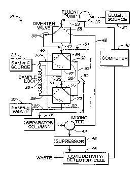
Attention is now directed to FIGURE 2 where an
apparatus, generally designated 20, for chromatographic
separation and quantitative analysis of ionic species
in a sample solution is illustrated. Chromatographic
separation apparatus 20 includes an eluent source 21
providing pressurized eluent at a substantially
constant flow rate, and a sample source 122 of the
sample solution having an input port 23 and a waste
port 25. A sample injection loop, generally designated
26, is included having a sample inlet 27 and a sample
outlet 28 to enable loading the sample solution in loop
26. The injection loop has a known volume in the range
of about 100 ~.L to about 8 mL. This is specifically
accomplished by tubing having a predetermined inner
diameter in the range of about 0.5 mm to about 3 mm,
the reasons of which will be described in greater
detail below. Further, the present invention includes
a separator column 30 having ion exchange resin capable
of preconcentration of the trace ionic contaminants
therein, and an injection valve assembly, generally
designated 31, having a first valve portion 32 and a
second valve portion 33. First valve portion 32 is in
selective fluid communication with eluent source 21,
sample inlet 27 and sample input port 23, while second
valve portion 33 is in selective fluid communication
with sample waste port 25, sample outlet 28 and
.. separator column 30.
Injection valve assembly 31 controls first and second
valve portions 32, 33 to load sample injection loop 26
completely with sample solution from sample source 22,
CA 02238549 1998-OS-26
WO 97!22876 PCT/iJS96/19979
-10-
while removing any non-sample solutions therefrom
(FIGURE 2). Subsequently, injection valve assembly 31
closes fluid communication between the sample source
and the injection loop, and opens fluid communication
between the high precision eluent pump 35 and the
sample loop 26 (FIGURE 3). This urges the pumped ,
eluent into contact with the sample solution contained
in the injection loop to sweep the sample solution
through the separator column 30.
In accordance with the present invention, by precisely
controlling the flow rate and operation time of the
high precision eluent pump, a precise volume of eluent
can be delivered through the system. In turn, the
precise volume of eluent delivered to the injection
loop displaces an equivalent volume of sample solution
from the injection loop. Hence, a precise, calculated
volume of sample solution will be subsequently passed
through separator column 30.
Moreover, this assembly eliminates the need for an
independent sample pump as a means to drive the sample
solution through the resin column for on-column
preconcentration since the more precise eluent pump 35,
in combination with injection valve assembly 31, is
employed. Manufacturing costs are therefore decreased,
as well as reducing maintenance costs. The present
invention further eliminates the need for a separate
concentration column since the separator column is
suitable for both a concentration column and a
separator column.
The present invention on-column preconcentration, .
however, is initially limited to an amount of sample
solution no greater than the known volume provided by ,
injection loop 26. This presents a substantial problem
since the known volume of the sample injection loop of
CA 02238549 1998-OS-26
WO 97!22876 PCT/US96/19979
-11-
the present invention is relatively small (i.e., about
100 ~.L to about 2 mL for a 2 mm separator column, and
about 400 ~.~,L to about 8 mL for a 4 mm separator column)
q due to the relatively small inner diameter tube (i.e.,
about 0.5 to about 1 mm for a 2 mm separator column,
and about 1 mm to about 3 mm for a 4 mm separator
column). As above-indicated, this dimensional
configuration is desirable to reduce potential rupture
of the sample loop when subjected to the substantially
higher pressures provided by the eluent pump and the
separator column. Moreover, the reduced tube length of
the injection loop increases analytical performance by
increasing volume reproducibility and reliability due
to less bubble retention.
The drawback to this configuration, however, is that
the resulting small volume of sample solution provided
by the injection loop is an amount insufficient to
perform on-column preconcentration for trace analysis.
The prior art on-column preconcentration assemblies
could merely replace the injection loops with larger
volume sample injection loops which often resulted in
the above-mentioned analytical problems or the like.
In contrast, the present invention employs a multi-
cycle on-column preconcentration loading technique to
cumulatively pass through the resin column the proper
quantity of sample solution. Therefore, as will be
described in greater detail below, several cycles of
loading the injection loop with sample (FIGURE 2),
sweeping the sample therein to the resin column by the
eluent pump (FIGURE 3), and then loading the sample
injection loop again are required.
One problem associated with multi-cycle loading for on-
column preconcentration, however, is passing or
sweeping through the injection loop a volume of eluent
greater than the known volume of sample solution
CA 02238549 1998-OS-26
WO 97/22876 PCT/US96/19979
-12-
retained in the injection loop. In this event, some of
the eluent may inadvertently pass through injection
loop 2& into a connecting conduit 36 (FIGURE 3), and
prematurely through the ion exchange resin column 30
causing chromatographic elution. Hence, certain ions
captured in the ion exchange resin may be prematurely ,
released or separated from the column which results in
degradation of the chromatographic separation and
comprises quantitation.
To eliminate eluent from passing through resin column
30 during fluid communication between the eluent source
and the injection loop (FIGURE 3), in accordance with
the present invention, less than 100 of the known
volume of the injection loop will be displaced in one
cycle. In the preferred form, up to about 98~ may be
displaced, and more preferably, 5o to about 95~ will be
displaced for loading of the resin column. This
technique assures that eluent will not be prematurely
passed into connecting conduit 36, and on through the
resin column to cause inadvertent ion separation from
the resin during the sample solution loading sequence.
Subsequently, injection valve assembly 31 is
selectively configured to close fluid communication of
sample injection loop 26 with resin column 30 and
eluent source 21; and reopen fluid communication of the
injection loop with sample solution source 22 and
sample waste 37. As above-mentioned, this procedure
loads or fills injection loop with the known volume of
sample solution while simultaneously removing any non-
sample solutions, such as eluent, from the injection
loop.
By employing the high precision eluent pump, the
quantity or volume of sample solution delivered is ,
highly reproducible. Accordingly, the present
invention is particularly suitable for the mufti-cycle
CA 02238549 2002-02-05
61051-2043
13
on-column preconcentra~_ion technique. By sequentially
repeating or cycling th::is procedure over and over, an
accurate cumulative vo:'_ume of sample solution can be passed
through the resin column for concentration of the trace ions
thereon. That is, the 1=:race ions from each calculated
portion (i.e., up to 98'- of the Xn~~wn volume) of sample
solution will concentr~i_.e on the resi.:n column. In this
manner, resin column 3t:) is further employed as a
concentration column. ~F'his system also operates with a
guard column placed between injection valve 31 and separator
column 30.
For example, for an on-column preconcentration.
requiring about 20 mL :o.f sample solution to perform trace
analysis, and a system employing a sample loop having a
known volume of about ~ mL, at about 80o displacement of the
known volume of inject~c>n loop, at Least 25 cycles would be
required to pass a cum~.z.:l.ative volume of 20 ml of sample
solution through resin column.
Subsequently, as schematically illustrated in
FIGURE 4, injection va:'_u~e assembly 31_ can be configured to
enable eluent to pass ,hrough resin column 30 for elution of
the particular anion anc't ration species from the ion
exchange resin. This c:~:lution procedure, as well as the ion
exchange resins employ=~c.E, are well known in the field anal
are described in greater detail in U.S. Patent No.
4,314,823.
Turning back t.o FIGURE 2, the present invention
will be described in dc=~t.ail. Briefly, sample injection loop
26 is preferably provi~::Fed by flexible inert tubing such as
TEFLON°, tefzelTM or Po:'~yether-ether ketone (PEEK). Opposite
ends (i.e., sample inlr:at. 27 and sarnpl_e outlet 28) of loop 26
are coupled to injection va:Lve assembly
CA 02238549 1998-OS-26
WO 97122876 PCT/US96/19979
-14-
31 to control fluid communication thereof with eluent
source 21/resin column 30, and with sample source
22/sample waste 37.
Injection valve assembly 31 includes first valve
portion 32, selectively fluid communicating sample
inlet 27 with either eluent source 21 or the sample
input port 23 of sample source 22. Further, valve
portion assembly 31 includes second valve portion 33,
selectively fluid communicating sample outlet 28 with
either sample waste port 25 or the resin/separator
column 30.
First valve portion 32 is selectively movable between
a loop loading position (FIGURE 2) and a column loading
position (FIGURE 3). In the loop loading position,
first valve portion 32 fluid couples sample inlet 27
with sample input port 23 (as illustrated by solid line
47 in FIGURE 2) to enable loading of injection loop 26
with the sample solution. In contrast, in the column
loading position, first valve portion 32 couples eluent
source 21 with sample inlet 27 (solid line 48 in FIGURE
3) to displace up to about 98~ of the known volume
sample solution from injection loop 26 toward the
second valve portion.
In a similar manner, second valve portion 33 is
selectively movable between a loop loading condition
(FIGURE 2) and a column loading condition (FIGURE 3).
In the loop loading condition, second valve portion 33
fluid couples sample outlet 28 with the sample waste
port 25 (as illustrated by solid line 50 in FIGURE 2)
to load injection loop 26 with the sample solution when
first valve portion 32 is in the loop loading position.
In contrast, in the column loading condition, second
valve portion 33 fluid couples sample outlet 28 with
separator column 30 (solid line 51 in FIGURE 3) to
CA 02238549 1998-OS-26
WO 97/22876 PCT/LTS96/I9979
-15-
enable sample solution flow from injection loop 26 and
second valve portion 33 to separator column 30 when the
first valve portion is in the column loading position.
Accordingly, when both the first valve portion 32 is in
the loop loading position and the second valve portion
33 is in the loop loading condition, sample source will
urge new sample solution into injection loop 26 (as
shown by arrows 52 in FIGURE 2). Consequently, non-
sample solution resident in sample injection loop 26
will be removed therefrom and urged toward sample waste
port 25 during loading.
Depending upon the sample flow rate, which is
proportional to the sample supply pressure (,typically
between about 10 psi to about 100 psi) and the known
volume of injection loop 26, the time required to load
the sample injection loop may vary between about 10
seconds to about 300 seconds. As mentioned, this
loading technique is performed without a sample pump.
In accordance with the present invention, injection
valve assembly 31 further includes a bypass tube 38
selectively fluid coupling eluent source 21 with
separator column 30 in a manner bypassing injection
loop 26 to enable chromatographic separation. This
configuration is employed after the on-column
preconcentration has been completed, and ion
chromatographic separation is about to commence.
As shown in FIGURE 4, bypass tube 38 is coupled between
first valve portion 32 and second valve portion 33 for
direct fluid communication therebetween. Arrows 53
illustrate that eluent source 21 is placed in direct
fluid communication with separator column 30 for trace
analysis such that the eluent flows directly through
both first valve portion 32 and second valve portion 33
CA 02238549 2002-02-05
61051-2043
16
to connecting conduit 36. Hence, first valve portion 32 is
further selectively movable to a bypass position, providing
fluid communication between eluent source 21 with second
valve portion 33 (as i.L.l.ustrated by solid line 55 in FIGURE
4), while first valve portion 32 is out of the column
loading position. Simi:l_arl:y, second valve portion 33 i~c
further selectively movable to a bypass condition, providing
direct fluid communicat:i_on between first valve portion 32
and separator column 30 (so.lid line '_>6 in FIGURE 4), to
enable passage of elueTnt: through separator column 30 for
chromatographic separation. It will be understood that in
this configuration, se~~ond valve portion 33 is out of column
loading condition and .:first valve portion 32 is in the
bypass position.
First valve portion 32 and second valve portic>n 33
are preferably provide~:l by ~~onventiorral valves commonly
employed in the ion chromatographic and the HPLC fields.
Hence, the valves may be mechanically or pneumatically
actuated with an actuat:i_on device su<:h as computer 40.
Further, eluent pump 35 is preferably provided by a dual.
piston pump having sup~~xv.ior flow properties such as tho~~e
provided by high preci:~i_on :IC or HPLC: pumps. In the
preferred embodiment, U~he flow rate is between 0.1 to 2.0
mL/min. These pumps, of course, must be capable of
substantial precision to maintain a substantially constant
flow rate for predetermi_rled periods of time.
A diverter va:l_ve 41 may be provided upstream from
injection valve assemb:l~r~ 31 which can redirect eluent flow
through a bypass conduit. 42 coupling eluent source 21
directly to a mixing te:e 43, bypassing injection valve
assembly 31. This valve is employed to bypass the injecaion
valve assembly 31, sample: injection loop 26 and separate>r
column 30 while first ~ralve portion 32
CA 02238549 1998-OS-26
WO 97/22876 PCT/US96/19979
-17-
and second valve portion 33 are deployed in the. loop
loading position and the loop loading condition,
respectively (FIGURE 2). In this configuration, as
shown by arrows S7, eluent is assured to flow
continuously through suppressor 45 and detector 46
which is imperative to maintain detector stability.
Separator column 30 is provided by a high performance
ion chromatography column capable of separating the
analytes (contaminants) of interest. Typical of these
columns is the DIONEX CS12A (2mm) chromatographic
separator. Further, suppressor 45 is employed to
enhance detection when a flow through conductivity
detector is used. Typical of these suppressors are
disclosed in U.S. Patent Nos.: 4,999,098; 5,248,426;
and 5,352,360, herein incorporated by reference. Other
detectors, however, such as electrochemical or
photometric could be employed in this invention with or
without a suppressor.
The computer 40 is capable of acquiring output from the
detector and also can be used to control the
chromatographic system. Hence, the microprocessor or
computer 40 can be employed to actuate diverter valve
41 and injection valve assembly 31 at any time during
the analysis.
In addition, this embodiment allows for quantitation
calibration using a similar scheme. In this case, the
specified volume of standard delivered is between 5 and
95% of the injection loop volume. Typically, only one
loading cycle is used for calibration although the
calibration scheme may involve loading at different
volumes or standards at different concentrations. This
process allows for quantitation calibration to be
performed using standards with concentrations
significantly higher than the samples to be analyzed.
CA 02238549 1998-OS-26
WO 97!22876 PCT/I1S96l19979
_~8_
This procedure minimizes the error caused by having to
prepare standards at lower concentrations which may be
contaminated by the water used for dilution.
For example, suppose one wishes to determine the ionic
contamination in HPw at the 1 ~.~.g/L (ppb) level. Using ,
the present invention would require loading
approximately 5 mL of sample to achieve the required
detection limits. A typical sample loop volume is 1.3
mL. Typically, a standard curve would be established
from 0.1 - 20.0 /,tg/L. This would normally require
preparing standards at the 0.1, 1.0 and 10.0 ~,g/L
levels. As mentioned, accurate preparation and storage
of low level standards is difficult due to
contamination and stability of the standards. Suppose
that for standardization, a 10.0 ~,g/L standard was
prepared. With proper care, an accurate 10.0 fcg/L
standard can be prepared without contamination. The
first calibration point (0.1 ~g/L) would be generated
by allowing only 50 E.cL of the standard to load to the
separator column. The 1.0 ~,g/L calibration would be
accomplished by allowing 500 ~,L of the 10.0 ~,g/L
standard to load to the concentrator column. Finally,
the 10.0 ug/L calibration would be accomplished by
allowing 5.0 mL of the 10 ~.cg/L standard to load to the
separator.
SEQUENCE OF OPERATION
The following description will refer to one sequence of
operation of the system of FIGURES 2-4. For simplicity
of description, flow of solutions will be described in
order of flow without reference to valve settings. The
valves will be assumed to allow flow in the described -
manner.
In the first step, sample injection loop 26 is loaded
with sample solution, having trace ionic contaminants,
CA 02238549 1998-OS-26
WO 97/22876 PCT/US96/19979
-19-
substantially filling loop 26 therewith and removing
any non-sample solutions therefrom. This is
accomplished first moving diverter valve 41 to a bypass
position (shown by solid line 58 in FIGURE 2) which
directs eluent from eluent source 21 and eluent pump
through mixing tee 43 and onto suppressor 45. As
mentioned, this assures fluid flow through the
suppressor to maintain stability, as illustrated by
arrows 57.
Simultaneously, first valve portion 32 and second valve
portion 33 are switched to the loop loading position
(as illustrated by solid line 47 in FIGURE 2) and the
loop loading condition (solid line 50), respectively.
Sample solution will then flow (as illustrated by
arrows 52) through injection loop 26 while
simultaneously removing any resident eluent or the like
to sample waste 37. Depending upon the capacity or
volume of the sample injection loop and the flow rate
of the sample solution, the time required to load the
loop may vary from 10 - 300 seconds.
After completion of filling injection loop 26, first
valve portion 32 and second valve portion 33 are
switched to the column loading position (as illustrated
by solid line 48 in FIGURE 3) and the column loading
condition (solid line 51), respectively. Hence, eluent
pump directs pressurized eluent, at a substantially
constant rate and for a predetermined period of time to
sample injection loop 26, as illustrated by arrows 60.
Moreover, up to about 98~ of the known volume of the
sample solution is displaced by eluent so that an
~ equivalent amount passes through connecting conduit 36
and through ion exchange resin column 30.
This is most preferably controlled by the actuation of
diverter valve 41 for a predetermined period of time to
CA 02238549 1998-OS-26
WO 97122876 PC'1'/US96/19979
-20-
enable fluid communication between eluent source 21 and
injection valve'assembly 31. For example if a sample
injection loop of 1.0 mL was used and the eluent flow
rate from eluent pump 35 was 0.2 mL/minutes, and the .
system was configured to load 80% (0.8 mL) of the
contents or known volume of injection loop 26, diverter
valve 41 would direct eluent through valve assembly 31,
and hence, to injection loop 26 for 4 minutes (0.8
mL/0.2 mL/min.). Subsequently, diverter valve 41 will
be switched to the bypass position (as illustrated by
solid line 58 in FIGURE 2) to direct eluent flow from
injection valve assembly 31 back to mixing tee 43 and
onto the suppressor 45 and cell/detector 46. This
assures that there is always flow through the
suppressor detector which is important in maintaining
detector stability.
In accordance with the present invention, the above
mentioned steps are repeated sequentially until the
predetermined total or cumulative volume of sample
solution has passed through separator column 30 for on-
column preconcentration for trace analysis. Hence,
this method of sample loading enables a precise, large
volume of sample to be loaded to the separator column
without eluent passing through the column. If eluent
passes to the separator after sampling loading,
chromatographic elution will begin which is undesirable
at this stage of the analysis.
The next step includes switching first valve portion 32
and second valve portion 33 to the bypass position (as
illustrated by solid line 55 in FIGURE 4) and the
bypass condition (solid line 56), respectively. In
this configuration the eluent is passed through the ion
exchange resin column, as represented by arrows 53, to
cause chromatographic elution.
CA 02238549 2002-02-05
61051-2043
21
In the alternative, during the last pass, the
entire injection loop volume may be -'loaded onto separator
column 30, and the chromatographic e-'~ution process may begin
as the eluent reaches r~iE~ separator column.
EXAMPLE 1
A DionexTM DX500 chromatograph was configured as
shown in FIGURE 2. Chromatography separations of inorganic
cations was accomplished using a DionexTM CS12A (2mm)
separator and detection used a DionexTM CSR.S-2mm suppresaor.
The injection loop size was 1300uL oj_ which approximately
770 (1000uL) was loaded onto the separator. The test sample
consisted of 18.2MS2-cm deionized water to which was added
the following test ana:Lytes at ug/L ;ppb) concentrations>:
lithium - 0.38 ug/L,
sodium - 1.5 yg/L,
ammonium - 1.~~ ug/L,
potassium - :3.8 ug/L,
magnesium - 1.9 ug/L, and
calcium - 3.~3 ~g/L.
The timed events program used controlled sample
loading. FIGURE 5 is ~:~ chromatogram obtained using a single
and five-cycle sample loading. Note that no chromatographic
degradation is observed and, as expected, the peak respc>nse
is increased approximal~ely five fold for the five-cycle
experiment. In order loo demonstrate the linearity and
precision of the multi--cycle sample 7_oading technique, the
data obtained for peak area of each c>f the components was
plotted against the curmalat:ive number of passes (1-5). If
each pass resulted in f=lue same volume, the relationship
should be linear. Table I .shows detection
CA 02238549 2002-02-05
61051-2043
21a
limits and examination c>f the data shows that the
concentration for each anal:yte in the five pass chromatogram
is about one-fifth that. of the single pass. This is
consistent with precise sampling loading volumes during each
pass.
CA 02238549 1998-OS-26
WO 97122876 PCT/US96/19979
-22-
Moreover, FIGURE 6 shows the results obtained for
potassium, while FIGURE 7 illustrates the results for
calcium. As can be seen from these results, the
precision of multicycle sample loading is extremely
good.
TABLE 1
(Analyte Concentration (~,cg/L.))
Analyte Sincrle Pass Quintuple Pass
Lithium 0.0061 0.0013
Sodium 0.016 0.0032
Ammonium 0.018 0.0049
Potassium 0.035 0.0072
Magnesium 0.025 0.0047
Calcium 0.044 0.0084
While the present invention is most suitable for use in
ion chromatography, it will be appreciated that the
present invention may be employed in High Performance
Liquid Chromatography (HPLC) as well. In this
embodiment, the separator column would be replaced by
a normal or reverse phase column. Further, those
skilled in the art would recognize that the analogous
eluents employed in HPLC would replace those employed
in ion chromatography.