Note: Descriptions are shown in the official language in which they were submitted.
CA 02238606 1998-0~-2~
CASCADED OPTICAL MULTIPLEXING DEVICES
INTRODUCTION
The present invention is directed to an optical multiplexing device which
spatially disburses multi-channel collim~te~l light from an optical waveguide into
individual channels, each of which can be directed to an individual optical waveguide,
light detector, etc., and/or multiplexes channels to a con~non optical waveguide or
other destination. In certain preferred embodiments, the optical multiplexing devices of
the present invention are particularly well suited for dense channel wavelength division
multiplexing systems for fiber-optic telecommunications systems.
BACKGROUND
Wavelength division multiplexing of optical signals is finding widespread use invarious fields, including especially for data transmission and other telecommunication
applications. The cost of new installed fiber-optic cable presents a barrier to increased
carrying capacity, which can be addressed by wavelength division multiplexing.
Wavelength division multiplexing allows multiple signals to be carried simultaneously
by a fiber-optic line or other waveguide. Presently preferred wavelength bands for
fiber-optic tr~n~mi.~ion media include those centered at 1.3!1 and 1.55~1. The latter is
especially preferred because of its minim~l absorption and the commercial availability
of erbium doped fiber arnplifiers. The useful bandwidth is approximately 10 to 40 nm,
depending on application. Wavelength division multiplexing can separate this
bandwidth into multiple channels. Ideally, the 1.55~ wavelength band, for example,
would be divided into multiple discrete channels, such as 4, 8, 16 or even as many as 32
CA 02238606 1998-0~-2~
or more channels, through a technique referred to as dense channel wavelength division
multiplexing, as a low cost method of substantially increasing a waveguide's signal
carrying capacity, such as long-haul telecommunication capacity over existing fiber-
optic tr~n.~mis.sion lines. The International Telephony Union (ITU) Grid provides
S standard center wavelengths for channels in the 1.5511 wavelength band, at 100 Ghz
spacing (approximately 0.8 nm). Wavelength division multiplexing may be used to
supply telephony and data transmission and, more and more in the future, such services
as video-on-demand and other existing or planned multimedia, interactive services.
Techniques and devices are required, however, for multiplexing the different discrete
carrier wavelengths. That is, the individual optic signals must be combined onto a
common fiber-optical waveguide and then later separated again into the individual
signals or channels at the opposite end of the fiber-optic cable. Thus, the ability to
effectively combine and then separate individual channels (or wavelength bands) on a
fiber-optic trunk line or other optical signal source is of growing importance to fiber-
optic telecommunications and other fields.
Known devices for this purpose have employed, for example, diffraction
gratings, prisms and various types of fixed or tunable filters. Gratings and prisms
typically require complicated and bulky alignment systems and have been found toprovide poor efficiency and poor stability under ch~nging arnbient conditions. Fixed
wavelength filters, such as interference coatings, can be made substantially more stable.
In this regard, highly improved interference coatings of metal oxide materials, such as
niobia and silica, can be produced by commercially known plasma deposition
techniques, such as ion assisted electron beam evaporation, ion beam sputtering, and
reactive magnetron sputtering, e.g., as disclosed in U.S. patent No. 4,851,095 to Scobey
et al. Such coating methods can produce interference cavity filters formed of stacked
dielectric optical coatings which are advantageously dense and stable, with low film
scatter and low absorption, as well as low sensitivity to temperature changes and
ambient humidity.
It is known to optically couple a tr mk line carrying multiple channels to a
common port of a wavelength division multiplexer (''WDM" - this term is used here to
mean devices which combine signals, separate signals or both). Such WOM common
CA 02238606 1998-0~-2~
port is, in turn, optically coupled within the WDM to multiple channel ports.
Associated with each channel port is an interference filter or the like which issubstantially transparent to the wavelength band of that particular channel. Thus,
signals having the wavelength assigned to a particular channel are passed by the WDM
S through its respective channel port to and/or from the individual waveguide for that
channel.
Interference filters of the Fabry-Perot type, which are preferred in various
multiplexing applications, typically transmit only a single wavelength or range of
wavelengths. Multiple filter units can be used together in a WDM, e.g., on a common
1 () parallelogram prism or other optical block. Multiple optical filters are joined together,
for example, in the multiplexing device of U.K. patent application GB 2,014,752A to
separate light of different wavelengths transmitted down a common optical waveguide.
At least two transmission filters, each of which transmits light of a different
predetermined wavelength and reflects light of other wavelengths, are attached adjacent
15 each other to a transparent substrate. The optical filters are arranged so that an optical
beam is partially transmitted and partially reflected by each optical filter in turn,
producing a zigzag light path. Light of a particular wavelength is subtracted or added
at each filter. Similarly, in the multiplexing device of European patent application No.
85102054.5 to Oki Electric Industry Co., Ltd., a so-called hybrid optical wavelength
20 division multiplexer-demultiplexer is suggested, wherein multiple separate interference
filters of different transmissivities are applied to the side surfaces of a glass block. A
somewhat related approach is suggested in U.S. patent 5,005,935 to Kunikani et al,
wherein a wavelength division multiplexing optical transmission system for use in bi-
directional optical fiber communications between a central telephone exchange and a
25 remote subscriber employs multiple separately located multiplexers each having
separate filter elements applied to various surfaces of a parallelogram prism.
Alternative approaches for tapping selective wavelengths from a main trunk line
carrying optical signals on a plurality of wavelength bands is suggested, for example, in
U.S. patent 4,768.849 to Hicks, Jr. In that patent multiple filter taps, each employing
3() dielectric mirrors and lenses for removing (or adding) one channel from a multi-channel
trunk line, are shown in use singly and in arrays for removing a series of channels.
CA 02238606 1998-0~-2
Achieving the objective of multiplexing signals ever more densely presents
certain problems. Light passed from a trunk line through a comrnon port of a WDM,
such as a filter-based WDM wherein the light travels generally as a so-called expanded
beam for at least a portion of the distance will spread or disperse as a function of travel
5 distance. For example, it travels within a glass optical block and/or other components
of the WDM rather than in a waveguide. There are practical limits on the distance a
multi-channel light beam can travel as an expanded beam before unacceptable signal
degradation occurs. Current four-channel WDMs employing a zigzag expanded beam
light path are effective in part because of the relatively short distance traveled by the
l O expanded beam relative to the focal length of commercially available collimators
typically used at the common port of current WDMs, before the light is passed through
one or another of the channel ports, collimated and passed back into to a waveguide.
Four-channel multiplexing, however, does not meet the growing need for 8 channelmultiplexing systems, 16 channel systems, etc. It has not proved acceptable for many
l S applications to simply enlarge current WDM devices to extend the zigzag expanded
bearn to impinge in sequence on 8 or 16 interference filters. The longer distance
traveled by the expanded beam is found to cause undesirable signal degradation.
A related problem in developing WDMs of the type discussed above employing
multiple filter elements mounted in parallel to an optical block, for multiplexing more
20 than four channels, especially expanded beam WDMs using selectively transparent
filter elements, lies in the difficulty of "kitting" the larger number of filter elements.
Typically, a filter element for any given channel is produced with a passband which is
centered imprecisely at the center wavelength for that channel. The passband of the
filter element can be adjusted to be more precisely centered by ch~nging the angle of
25 incidence of the expanded beam on the filter element. This can be done by slightly
tilting the filter relative to the light beam. In a typical WDM of this type, the multiple
individual filter elements are mounted together side-by-side on one or more flatsurfaces of an optical block of the WDM. Ch~nging the input angle of the beam from
the trunk line at the common port, typically by tilting the optical block, correspondingly
30 changes the angle of incidence of the expanded beam within the WDM on the filter of
not just one charmel port, but of every channel port of the WDM. Thus, tilting the
-
CA 02238606 1998-0~-2~
optical block to more precisely center the wavelength sub-range of a given channel is
effective only if the filter of each other channel is imprecisely centered in the same
direction and approximately the same amount relative to its respective wavelength sub-
range.
S For this reason, filters for a WDM are "kitted." That is~ a set of filters is
collected for a given WI)M, all having approximately the same wavelength deviations:
each is off-center in the same direction and approximately the same amount relative to
its respective wavelength sub-range. The assembled WDM can then be tuned by tilting
the optical block to which the filters have been mounted. This applies approximately
the same correcting wavelength shifts at each channel port. Since the "kitted" filters all
have approximately the same wavelength deviation, such common wavelength
correction simultaneously renders each of the channel ports more precisely centered for
its respective wavelength sub-range. Kitting the filters is an assembling task, however,
which becomes more complex, more expensive and more time consuming as the
number of filters in the kit increases. Thus enlarging a 4-port WDM to an ~-port W~)M
would involve an undesirable increase in assembly time, cost and complexity to collect
the kits of eight filters. The problem would be far worse for a 16 channel ~DM. It
would be advantageous, therefore, to avoid the need to collect larger filter kits in
connection with increasing the number of channels multiplexed by a system
Another problem hindering the development of wavelength division
multiplexing systems with greater numbers of channels involves channel spacing. As
noted above, a limited band width is used in such systems, and therefore it is desirable
to space adjacent channels closely together. That is the center wavelength for one
channel must be closely spaced to the center wavelength of the adjacent channel on
either side of it. The passband of even a high quality interference filter is imperfect,
however, such that not only the desired wavelength sub-range assigned to a particular
channel is passed, but also to a lesser extent adjacent wavelengths (i.e., adjacent
channels) are unavoidably passed by the filter along with the desired signal for that
channel. Filter quality in this regard can be measured by their so-called figure of merit
("FOM"). A good FOM means a filter has a wavelength passband with a flat top
(centered at the desired wavelength) and steep sides. Currently. 40% FOM is
-
CA 02238606 1998-0~-2~
considered good, meaning that the base of the wavelength passband (measured e.g., at 1
dB) is twice the width of the top of the wavelength passband (measured e.g., at 20 dB).
Filters having a better FOM are more costly to produce and, hence, are unsuitable for
many applications. In a system where the wavelength sub-range for each channel is
5 spaced by a like wavelength width from each adjacent wavelength sub-range, a single
channel interference filter with a 40% FOM is well suited to removing the desired
wavelength sub-range from an expanded beam of multi-channel light. The passband of
such a filter will typically have acceptably low transmittance of wavelengths which are
more than about one-half channel width to either side. Such filter, therefore, is
10 substantially reflective ofthe wavelength sub-range ofthe adjacent channels, since they
are spaced a full channel width away. It is significant in this regard that various
proposed dense wavelength division multiplexing schemes have voluntarily sacrificed
otherwise usable bandwidth in attempting to overcome the FOM problem.
Multiplexing arrangements have been suggested, employing a beam splitter to
15 multiplex an eight-channel short band with an eight-channel long band. Even with a
good FOM, several channels between the long band and short band are left unused in
such suggested arrangements. Because the tops of the two adjacent passbands are wide
(eight channels), the base of each is correspondingly wide, such that there is
unacceptably high tr~n.~mi~ion with both of the two adjacent passbands of the
20 interrnediate wavelengths between them. Thus, the intermediate wavelengths are
simply not used, resulting in the need to use instead less desirable wavelengths at the
outside of the long and short bands. It is an object of the present invention to provide
improved optical multiplexing devices which reduce or wholly overcome some or all of
the aforesaid difficulties inherent in prior known devices. Additional objects and
25 advantages of the invention will be apparent to those skilled in the art, that is, those
who are knowledgeable and experienced in this field of technology, in view of the
following disclosure of the invention and detailed description of certain preferred
embodiments.
CA 02238606 1998-0~-2~
SUMMARY
In accordance with the present invention, optical multiplexing devices are
provided comprising cascaded WDMs, that is, comprising multiple WDMs which are
5 optically coupled to a common trunk line carrying multi-channel wavelength
multiplexed light. The c~c~cled WDMs multiplex different channels or wavelength
sub-ranges. The WDMs are cascaded in parallel or in series, or a combination of both,
from the trunk line, each WDM adding and/or removing at least some channels or
wavelength sub-ranges not handled by the other WDM(s). Preferably, an optical port
10 of one WDM is optically coupled by a fiber-optic or other suitable waveguide to the
common port of a second WDM. The optical ports of the two WI)Ms pass different
channels or wavelength sub-ranges. The term "optically coupled" as used here in
describing, e.g., that the common port of one WDM is optically coupled to an optical
port of another WDM, means that an optical signal is (or can be) passed between them
15 in one or both directions. There may be optical components positioned between two
optically coupled points, such as collimators, an optical waveguide, wavelength
selective filters and post filters, etc. In accordance with certain preferred embodiments,
the optical multiplexing device comprises a third wavelength division multiplexer and a
waveguide optically coupling the common port of such third WDM to an optical port of
20 the first or second WDM. In yet other preferred embodiments a fourth and optionally
additional wavelength division multiplexers are employed, having a common port
optically coupled by a waveguide to an optical port of one of the other multiplexers. In
accordance with such cascading of the WDMs, at least some of the channel ports of
each of the multiple multiplexers employed in the optical multiplexing device will be
25 substantially transparent to a channel or wavelength sub-range different from at least
some of the channel ports of the other multiplexers of the device. As will be more fully
understood from the discussion below of the various preferred embodiments, the
wavelength sub-range of the channel ports of the cascaded WDMs may overlap. Thus,
in accordance with the cascading principle disclosed here, a selected channel port of a
30 first WDM is optically coupled to the common port of a second WDM. Typically,therefore, such selected channel port of the first WDM will be substantially transparent
CA 02238606 1998-0~-2~
to a wavelength sub-range inclusive of some or all the wavelength sub-ranges of the
channel ports of the second WDM. It will be understood from this disclosure, that
WDMs may be cascaded in accordance with various alternative embodiments in
parallel, in an in-line fashion, a branched fashion or a combination of such c~ccatling
5 alternative modes. In an in-line cascade, only one optical port of each cascaded WDM
is directly optically coupled (i.e., not through any other intermediate WDM) to the
common port of another WDM in the cascade. In a branched cascade, there is a first
WDM, and the common port of each other WDM(s) in the cascade is optically coupled
directly to a channel port or other optical port of the first WDM.
In accordance with one aspect, an optical multiplexing device comprises a first
wavelength division multiplexer having a common port and multiple optical ports. The
common port typically is adapted for optical coupling to a fiber-optic cable or other
waveguide for delivering or receiving multiplexed signals passed by the common port.
The multiple optical ports are, in turn, optically coupled to the common port, and
15 include multiple channel ports each selectively transparent to a corresponding
wavelength sub-range. Typically, the wavelength sub-range of each of the channelports falls within the wavelength range passed by the common port. In many
applications the common port ~ill be non-wavelength selective. That is, it will be
unfiltered or in any event transparent to all wavelengths carried by the trunk line or
20 other waveguide to which it is optically coupled. Optionally, the optical ports of the
wavelength division multiplexer further include a non-wavelength selective residual
port, as discussed further below. The optical multiplexing device disclosed in
accordance with this first aspect further includes a second wavelength di-ision
multiplexer having a common port and multiple optical ports substantially as described
25 above in connection with the first wavelength division multiplexer. A waveguide
optically couples an optical port of the first wavelength division multiplexer to the
common port of the second wavelength division multiplexer. The respective
wavelength sub-range of the first and second WDM channel ports each is different from
the other. As discussed further below, a first set of channels passed by the common
30 port of the first wavelength division multiplexer can be multiplexed by optical ports of
that multiplexer, with a second subset of the channels being passed by an optical port of
CA 02238606 1998-0~-2~
the first WDM to the common port of the second WDM to be multiplexed by the
optical ports of the second WDM. For example, for an eight-channel multiplexing
system two wavelength division multiplexers can be optically coupled in the manner
disclosed here, whereby four of the eight channels are multiplexed by the first WDM
5 and the rem~ining four are multiplexed by the second WDM which is cascaded with the
first WDM.
It is a significant advantage of at least certain preferred embodiments, that
significant reduction in assembly cost and complexity can be achieved. Most notably,
the "kitting" of filters is less costly and complex. Since each of the multiple WDMs in
10 a cascade has a smaller number of channel ports than would be required in one larger
WDM, filter elements need be collected together in smaller kits. That is, fewer filters
must be kitted together for each of the smaller WDMs used in a cascaded WDM
arrangement in accordance with this disclosure. Consequently, the filters of a given kit
can be more precisely matched to each other. That is, within cost, time and complexity
15 constraints of a typical WDM assembly operation, filters can be better matched as to
their deviation from center wavelength. The assembled WDM can, therefore, be more
precisely tuned for all of its channel ports.
It is in additional surprising result of this invention, that significantly reduced
insertion loss can be achieved by optical multiplexing devices for 8, 16 or more20 channels using cascaded WDMs in accordance with this disclosure. As mentionedabove, insertion loss increases with distance traveled by an expanded beam. In fact,
insertion loss increases rapidly beyond the distance traveled by an expanded beam in a
current four-port WDM. Whereas insertion loss may be only, e.g., 1 dB over the
distance traveled in a typical expanded beam four-port WDM, insertion loss would25 typically increase to more than double if the zigzag expanded beam light path were
extended within such WDM to eight channels (using comparable quality componentry).
The deterioration significantly increases, if such WDM were enlarged to 16 channels.
In typical preferred embodiments, the insertion loss associated with each cascade, that
is, associated with passing multiple channels from one WDM to the next WDM may be
30 only about 1/2 dB to 1 dB. Thus, by the use of cascading WDMs in accordance with
this disclosure an overall reduction in insertion loss can be achieved.
CA 02238606 1998-0~-2~
In accordance with another aspect. one or more of the cascaded WDMs
employed in the optical multiple~ing devices disclosed here employs channel
interleaving. More specifically, in a multiplexer defining at least three optical ports in
sequence from the common port, a first channel port is substantially transparent to a
S first wavelength sub-range and substantially reflective of other wavelengths. A second
channel port sequentially following the first channel port is substantially transparent to
a second wavelength sub-range and substantially reflective of other wavelengths. A
third port sequentially follo~ing the second channel port is substantially transparent to
a third wavelength sub-range which is intermediate the first and second wavelength
10 sub-ranges. More specifically, the third wavelength sub-range is intermediate in that
the numerical value of its center wavelength is numerically greater than one and less
than the other of the first and second sub-ranges. Thus, individual channels or
wavelength sub-ranges are removed from a multi-channel light beam in a nonsequential
order. In accordance with certain especially preferred embodiments, an interleaving
15 mode is employed which can be referred to as compounded interleaving of the optical
ports, wherein one or more channels added and/or removed by a first WDM are
interleaved with other channels which are added and/or removed by a second WDM
cascaded with the first WDM. Here, again, the channels are interleaved in that the
respective wavelength sub-range(s) of the one or more channels of the first WDM are
20 intermediate (by wavelength size) the sub-ranges of the channels of the second WDM.
It should be understood that an interleaved channel in such compounded interleaving
may actually be a multi-channel wavelenath sub-range, and it may be positioned
sequentially at one end of the sequence of channels handled by the optical multiplexing
device. As will be ap~a~ from the discussion below of various ~e~ d
25 embodiments, significant advantages can be realized through implementation ofchannel interleaving, especially in the context of cascaded WDMs. Notably, for
example, the cost, assembly and design complexity, and insertion loss associated with
post filters can be reduced. Post filters may be unnecessary at a channel port if the one
or two adjacent wavelength sub-ranges have previously been removed from the multi-
30 channel light beam. Moreover, in certain preferred embodiments in low loss and moreuniform variation in signal strength can be achieved by matching the insertion loss
CA 02238606 1998-0~-2~
contributed by a post filter for one channel port with the insertion loss associated with
c~cc~in~ other channels to a next Wl)M through a different channel port at which no
post filter is required due to channel interleaving.
Additional features and advantages of various embodiments of the optical
5 multiplexing devices disclosed here will be better understood from the following
detailed discussion.
BRIEF DESCRIPTION OF THE DRAWINGS
Certain preferred embodiments of the invention are discussed below with
reference to the accompanying drawings in which:
Fig. 1 is a schematic illustration of an optical multiplexing device in accordance
with one preferred embodiment comprising two cascaded wavelength division
multiplexers;
Fig. 2 is a schematic illustration of an optical multiplexing device in accordance
with an alternative preferred embodiment, showing two cascaded wavelength division
multiplexers each employing channel interleaving;
Fig. 3 is a schematic illustration of an optical multiplexing device in accordance
with an alternative preferred embodiment;
Fig. 4 is a schematic illustration of an alternative preferred embodiment;
Fig. 5 is a schematic illustration of an alternative preferred embodiment;
Fig. 6 is a schematic illustration of an alternative preferred embodiment
employing four cascaded WDMs employing channel interleaving;
Fig. 7 is a schematic illustration of an optical multiplexing device employing six
cascaded WDMs;
Fig. 8 is a schematic illustration of an alternative ~l~rell~d embodiment; and
Fig. 9 is a schematic illustration of an alternative preferred embodiment.
It should be understood that the optical multiplexing devices illustrated in thedrawings are not necessarily to scale, either in their various dimensions or angular
relationships. It will be well within the ability of those skilled in the art to select
suitable dimensions and angular relationships for such devices in view of the foregoing
disclosure and the following detailed description of preferred embodiments.
CA 02238606 1998-0~-2~
DETAILED DESCRIPTION OF CERTAIN PREFERRED EMBODIMENTS
The optical multiplexing device, as disclosed above, has numerous applications
including, for example, in fiber-optic telecommunication systems. Optical multiplexing
devices of this design also have application, for example, in test equipment and the like,
5 as well as laboratory instrumentation. For purposes of illustration, the preferred
embodiments described below in detail are dense channel wavelength division
multiplexing devices for multi-channel fiber-optic telecommunication systems
employing 8 channels, 16 channels or more. The above-described problems of signal
degradation and losses due to light beam divergence, cross talk losses, etc. from
l0 adjacent channels are reduced in such fiber-optic telecommunication systems.
Transparent, when used here, means at least substantially transparent to a
particular wavelength range or wavelength sub-range. Reflective, when used here,means at least substantially reflective of particular wavelength ranges or wavelength
sub-ranges. Residual light, when used here, refers to the light which passes through a
15 WDM's residual post, i.e., a non-wavelength selective optical port of the WDM, e.g.,
the light which passes from a WDM at the last point of a multi-point light path
downstream of the last charmel port. A residual port may pass no light, a singlechannel or multiple channels. Unless another meaning is clear from the context below,
a channel means one particular channel of the multi-channel light carried by a
20 multiplexed fiber-optic telecommunication system. A wavelength sub-range passed by
a channel port of a WDM may be a single channel or multiple channels. In this regard,
it will be understood from this disclosure that a channel port may pass multiplechannels to another WDM in accordance with the cascading feature. A filter for achannel port of a WDM can be produced to be transparent to a wavelength sub-range
25 encompassing multiple channels. As indicated above, multiplexing by a WDM here
refers to adding channels, removing channels or both. For simplicity of explanation,
only the demultiplexing functionality is described here in detail, since those skilled in
the art will readily understand the correlative multiplexing functionality. That is, those
skilled in the art will recognize how the same device can be employed in reverse to
30 multiplex optical signals from the individual channels.
CA 02238606 1998-0~-2
13
As is known in the fiber-optic telecommunications industry, each channel of a
wavelength multiplexed system has a wavelength sub-range w hich is a portion of the
full wavelength range of the light carried by the system. For commercial systems using
the 1 .551l wavelength band, the sub-range of each individual channel typically is
5 centered at one of the standard center wavelengths provided in the ITU Grid. As
mentioned above, the ITU Grid gives standard center wavelengths at 100 Ghz spacings.
In any particular fiber-optic system, depending on the selected spacing of adjacent
channels, each channel's center wavelength will be one, t vo or more 100 Ghz units
removed from the center wavelength of the adjacent channel on either side. The first
10 and last channel will, of course, have only a single adjacent channel.
Those skilled in the art, that is those with knowledge or experience in this
technology, will recognize that a certain unavoidable overlap, or cross talk, occurs from
each channel to the other channels. As noted above, this occurs because of the inability
of a WDM to separate one channel perfectly from the multiplexed signal. In a WDM15 using Fabry-Perot type interference filters, better signal isolation can be achieved using
a filter having a higher figure of merit. A filter with a greater number of cavities
typically will have a higher FOM than an otherwise comparable filter with fewer
cavities, but also is more expensive to produce and causes increased insertion loss.
Post filters also can improve signal isolation, but also add cost and increase insertion
20 loss. Signal cont~min~tion is naturally greater from channels that are adjacent to one
another. Thus, although a third channel will have some overlap with the first channel,
it is typically much less than that occurring with the adjacent second and fourth
channels. As now described with reference to certain preferred embodiments, improved
signal isolation with reduced insertion loss can be achieved using cascaded WDMs,
25 especially in connection with interleaving. Of course, better quality filters and/or post
filters, etc., can be used in conjunction u-ith the cascading and interleaving features
disclosed here, to achieve corresponding further improvements in system performance.
~ Numerous different WDMs are commercially knoun and suitable for use ascascaded WDMs in the optical multiplexing devices disclosed here. In accordance with
30 certain preferred embodiments, WDMs are employed comprising an optical block
carrying Fabry-Perot interference filters, and optionally other reflective elements, such
CA 02238606 1998-0~-2~
14
as broadband high reflectance mirror elements, to define a multi-bounce, zigzag
expanded beam light path through the optical block. The optical block can comprise a
solid, optically transparent glass, for exarnple, or define an air gap between parallel
opposite sides to which the filter elements are mounted. Optical blocks of the later type
S are disclosed in commonly owned U.S. Patent application Serial No. 08/800,963 filed
February 14, 1997, entitled Multiplexing Device with Precision Optical Block, the
disclosure of which is hereby incorporated by reference. WDMs also can be employed,
wherein multiple channel ports along a multi-bounce zigzag expanded bearn light path
are formed at spaced locations of a continuously variable filter element mounted to an
optical block. Suitable such WDMs are disclosed in commonly owned U.S. Patent No.
5,583,683 to Scobey, entitled Optical Multiplexing Device. Suitable alternative WDM
configurations will be apparent to those skilled in the art given the benefit of this
disclosure. The filters used in the cascaded WDMs preferably are dielectric, multi-
cavity, most preferably three cavity, film stack coatings of the type commonly known
in the optics industry as Fabry-Perot cavity filters, often referred to simply as cavity
filters. Two dielectric thin film stacks which by themselves form a reflector for the
optical wavelengths in question, are separated by a thicker cavity layer. This structure
is then repeated one or more times to produce a filter with enhanced blocking and
improved in-band transmission flatness. The net effect is to produce a narrowband
transmissive filter where in-band light is transmitted and out-of-band light is reflected.
Dichroic filters may also be used. This improved filter performance provides
commercially acceptable dense channel wavelength division multiplexing for fiber-
optic telecommunications applications of the optical multiplexing device. Multi-cavity
interference filters can be produced with dense, stable metal oxide film stacks using the
deposition techniques mentioned above. Such filters in preferred embodiments have
excellent thermal stability at 1550 nm and ultra-narrow bandwidths, separated by as
little as 2 nm, or even as little as 1 nm or less. Stable ultra-narrowband filters are
shown in SPIE Proceedings 7/1994. High-quality interference filters comprising
stacked layers of metal oxide materials, such as e.g., niobia and silica. can be produced
on suitable optical substrate, such as optical glass, fused silica, etc., e.g., the BK series
(such as BKI, BK3 and BK7), SSK1, WG320 and RG1000 available from Schott
CA 02238606 1998-0~-2~
Glaswerke (Mainz, Germany) and any suitable Pyrex(~3) optical glass from Corning, Inc.
(Corning, New York, U.S.A.). The filters can be formed by commercially known
plasma deposition techniques, such as ion assisted electron beam evaporation, ion beam
sputtering, and reactive magnetron sputtering, for example, as disclosed in U.S. patent
No. 4,851,095 to Scobey et al., and U.S. patent No. 5,525,199 to Scobey the entire
disclosure of both these patents being hereby incorporated by reference. Such coating
methods can produce interference cavity filters formed of stacked dielectric optical
coatings which are advantageously dense and stable, with low film scatter and low
absorption, as well as low sensitivity to temperature changes and ambient humidity.
Suitable filters are disclosed also in U.S. patent 4,957,371 to Pellicori et al. Suitable
alternative filter elements and the like will be app~llt to those skilled in the art in view
of this disclosure.
Referring now to the preferred embodiments illustrated in the drawings, the
optical multiplexing device of Fig.1 is seen to comprise cascaded WD~fs, including
first optical block 52 and second optical block 152. An optical waveguide 54, e.g.,
optical fiber suitable for carrying a multi-channel optical signal, communicates with
means for projecting collimated light, such as a fiber-optic GRIN lens collimator 56 or
the like. Collimator 56 couples highly collim~tçd light 58 to the optical block 52 at a
slight angle through common port 16 in first surface 12 of the optical block. Second
surface 14 of optical block 52 is spaced from and substantially parallel to first surface
12. Thus, multi-channel light carried by optical fiber 54 (preferably a single mode
fiber) is collim~ted by collimator 56 and directed through common port 16, from which
it passes through optical block 52, striking second surface 14 at channel port 18. Filter
20, located at channel port 18, is transparent to a sub-range of the wavelengths included
in the collimated light 58. Specifically, light 22 corresponding to channel l of the
telecommunication system passes through channel port 18 of the optical block 52
preferably to a collimator 24 associated with a first signal channel. A post filter 20' is
mounted between channel port filter 20 and collimator 24. Post filter 20' optionally is
substantially identical to filter 20. It provides greater signal isolation along with certain
insertion loss. The optical signal passed by channel port 18 is thereby transmitted as
channel l to an optical fiber, preferably single mode fiber 26, as a demultiplexed signal.
CA 02238606 1998-0~-2~
16
The filter 20 at channel port 18 is reflective of wavelengths which are not "in-band" of
the filter. This reflected light 28 is, therefore, reflected from second surface 14 of the
optical block 52 back to a second channel port 30 at first surface 12. Interference filter
32 at channel port 30 is transparent to a different wavelength or sub-range of
wavelengths than that of filter 20 at channel port 18. For dense channel wavelength
division multiplexing applications, the wavelength separation between each of the
multiple ports spaced along first and second surfaces 12 and l~ is preferably about 1.6
nm or less. Thus, at channel port 30 an optical signal corresponding to a secondchannel is transmitted through the filter 32 and post filter 32' to a collimator 34, and
from there to fiber-optic carrier 36 as channel 2. As at the first channel port 18, the
filter 32 at channel port 30 reflects light which is not in-band at that location. Thus, the
rem~ining portion 38 of the collimated light 58 which first entered the optical block 52
at common port 16 is reflected back from port 30 to a third channel port 40 on second
surface 14. Interference filter 41 at channel port 40 is transparent to yet a different
wavelength or sub-range of wavelengths than that of filters 20 and 32. Thus, filter 41
transmits an optical signal through post filter 41 ' to collimator ~3 and from there to
fiber-optic carrier 45 as channel 3. From channel port 40 the light which is not in-band
is reflected or bounced back to a fourth channel port 42 on first surface 12.
Interference filter 47 at channel port 42 is transparent to a different wavelength or sub-
range of wavelengths than that of filters 20, 32, and 41. Thus, filter 47 transmits an
optical signal through post filter 47' to collimator 49 and from there to fiber-optic
carrier 51 as channel 4. The light which is not in-band of filter 47 is then reflected to
unfiltered residual port 44 on second surface 14 where the rem~ining light exits optical
block 52, passes to a collimator 46, and then to fiber-optic carrier or other waveguide
48. The reflected wavelengths therefore are seen to pass through WDM 52 in a zigzag
multi-point light path, with the optical signal for each individual channel being
removed by successive bounces at first and second surfaces 12 and 14 until the light
reaches residual port 44.
While preferably the interference filters are reflective of all wavelengths which
are not in-band at each of the multiple channel ports, in certain embodiments each
could be reflective only of the wavelengths of optical signals ~hich had not been
CA 02238606 1998-0~-2~
extracted at an upstream channel port, that is, at a channel port encountered previously
along the multi-point light path. Also, those skilled in the art will understand from this
description that the optical multiplexing device of Fig. 1 is equally suitable for use in
combining the optical signals of the four individual channels. Thus, the residual port
44 and/or the multiple channel ports in first and second surfaces 12 and 14 would be
input ports, and common port 16 would be an output port to trunk line 54. The zigzag
expanded beam light would then, at least in part, proceed downstream from the bottom
(as viewed in Fig. 1) of the optical block 52 toward the top.
The common port 116 of second optical block 152 is optically coupled directly
to residual port 44. Optical fiber 48, carrying the residual light from residual port 44,
carries light to collimator 156 of second optical block 152. Collimated light 158 enters
second optical block 152 at common port 116. Second optical block 152 operates to
pass collimated light 158 along a multi-point expanded beam light path in a manner
similar to optical block 52. Channel port 118 has filter 120 and post filter 120' which
transmits an optical signal through collimator 124 to optical fiber 126 as channel 5.
Reflected light 128 strikes channel port 130 where a selected wavelength sub-range is
transmitted by filter 132 and post filter 132' through collimator 134 to optical fiber 136
as channel 6. Reflected light 138 strikes channel port 140 where it is partiallytransmitted by filter 141 and post filter 141' through collimator 143 to optical fiber 145
as channel 7. The reflected light from channel port 140 is partially transmitted by filter
147 and post filter 147' at channel port 142 through collimator 149 to optical fiber 151
as channel 8. The rem~ining light, if any, is reflected at channel port 142 and passes
through unfiltered (and, therefore, non-wavelength selective) residual port 144 and
collimator 146 to optical fiber 148.
It is to be appreciated that the number of channel ports in any of the present
optical multiplexing devices can vary, for example, from two, to four, to eight, and
even more. By constructing such an optical multiplexing device with four-port WDMs,
however, a significant advantage can be realized. Light beam divergence increases as
the light beam travels along the multi-point light path within the optical multiplexing
device. Placing a collimator at the residual port 44 of the first of the cascaded WDMs
collimates the light again, and cascading two such four-port WDMs results in less loss
CA 02238606 1998 - 0.7 - 2.7
18
due to such beam divergence than would a comparable single 8-port WDM. It is a
significant advantage realized by the optical multiplexing devices with cascadedWDMs disclosed here, that the signal degradation, i.e., insertion loss, etc., caused by a
cascade connection of one WDM to another, typically only about 1/2 dB to l dB using
S optical components currently commercially available, is less than the signal degradation
which would occur in an expanded beam WDM enlarged to 8 or 16 channel ports. Theadvantage is even greater when a cascade of three or four WDMs is compared to a
comparable single WDM enlarged to 16 channel ports.
It will be recognized by those skilled in the art that the optical multiplexing
10 device illustrated in Fig. 1 can provide highly efficient and compact multiplexing and
demultiplexing functionality. The optical block can have a width, e.g., of about 14.5
mm and a height of about 5.5 mm. Linear spacing of the optical ports on each of
surfaces 12 and 14 can be, for example, about 3.0 mm, with an overall linear dimension
of approximately 21.6 mm for the optical block. Generally, it is preferred in devices of
15 the type discussed here, to have a low entry angle or tilt angle (where zero degrees
would be normal to the surface of the optical block) at which light passes through the
common port l 6 (measuring the angle of the light outside the optical block) to reduce
polarization dependent effects. It also reduces adverse effects of collimated light
divergence on filter performance, since a lower entry angle results in more closely
20 spaced bounce points within the optical block and, therefore, a shorter travel path for
the light. Typically, the entry angle is less than 30, being preferably from 4 to 15,
more preferably 6 to 10, most preferably about 8 .
Typical specifications for an optical multiplexing device in accordance with a
pl~f~ d embodiment of Fig. 1 are shown in Table A, below.
CA 02238606 1998-0~-2
19
TABLE A
Number of Channels 8
Channel Center Wavelengths ITU Grid (192.1 THz reference)
Channel Spacing 200 Ghz
Channel Bandwidth 80 Ghz
Max Insertion Loss <4 dB
In-Band Insertion Loss Variation <1 dB
Isolation < -25 dB
Back Reflection < -45 dB
In Table A "Max Insertion Loss is the largest insertion loss perrnitted for any channel
in the device, and "In-Band Insertion Loss Variation" is the maximum permitted
5 differJnce between the insertion loss experienced by any one channel the loss
experienced by any other charmel of the device
Another preferred embodiment is shown in Fig. 2. A single, continuous,
variable thickness multi-cavity interference filter 21 may be provided on second surface
14 to provide filtering at channel ports 18 and 40. Filter 21 is most preferably a
10 continuous linearly variable filter. Filter 21 is transparent at channel port 18 to a sub-
range of wavelengths included in the collimated light 58. The light 22 passes in turn as
channel 1 to collimator 24 and single mode fiber 26. The continuous filter 21 atchannel port 18 is reflective of wavelengths that are not "in-band" of the filter at that
location. The light 28 reflected by continuous filter 21 at first channel port 18 strikes
15 first surface 12 at broadband high reflector 33 where it reflects back all wavelengths as
rem:~ining light 38 to channel port 40 at second surface 14. At channel port 40, the
continuous, variable thickness, multi-cavity interference filter 21 is transparent to a
different wavelength or sub-range of wavelengths than it is at channel port 18, and thus
transmits channel 2 to collimator 43 and optic fiber 45. Filter 21 additionally reflects
20 wavelengths that are not in-band back to reflector 33 on first surface 12 which in turn
reflects all wavelengths of the light back to residual port 44 at second surface 14. A
continuous, variable thickness filter referred to above is more completely described in
U.S. Patent 5,583,683 to Scobey the disclosure of which is incorporated herein by
CA 02238606 1998-0~-2
reference. It is to be appreciated that the multiple channel ports can comprise any
combination of interference filters and reflector elements, each of which are positioned
along the multi-point light path to cascade the collimated light throughout the optical
multiplexing device. An end cap (not sho~n) can optionally be located at residual port
5 44, to prevent tr:~n~mi~ion of any light out of the optical block at that port. The end
cap alternatively can be provided at any of the channel ports, and is preferablyremovable so as to provide future expansion by adding a filter, reflector, or other
component in its place.
Several advantages will be recognized from the foregoing description of the
10 preferred embodiments of Figs. 1 and 2. With respect to the embodiment of Fig. 1, it
can be seen that the two cascaded WDMs employed in the optical multiplexing device
can be substantially identical in construction, thereby reducing the cost and complexity
of the optical multiplexing device. Typically, of course, the two cascaded WI)Msemploy filter elements which differ, so as to pass the different wavelength sub-ranges
15 corresponding to their different channels, etc. Alternatively, in certain preferred
embodiments (particularly those employing interleaving, disclosed above and further
discussed below), it will be possible to use identical WDMs, simply tilting each at a
different angle relative the direction of light passing through its common port. This
produces an angle of incidence of the light beam on the channel ports of one WDM20 which differs from the angle of incidence on the channel ports of the other WDM, and
thereby yields different passbands corresponding to the different ch~nnels beingmultiplexed by the system. Similarly, the second WDM in the embodiment of Fig. 2could be substantially identical to the first WDM. Rather than the individual filter
elements shown, such second WDM could employ continuous filters as are used in the
25 first WDM. In that case, the passbands of the correspondingly located channel ports of
the second WDM can be made to differ from the passbands of the channel ports of the
first WDM by differential tilting, as mentioned immediately above, or by employing
continuous filter elements having different light tr~nsmis~ion properties, or by using
substantially identical continuous filter elements which are simply shifted as to their
30 mounting position on the optical block. so as to cause the channel ports to occur at
different locations on the filter in the second WDM than in the first WDM. It should
CA 02238606 1998-OS-2S
also be recognized that an advantage is realized through the use of four-port WDMs in
the preferred embodiments of Figs. 1 and 2. Specifically, only six collimators per
WDM are required. Thus, six collimators serve to multiplex four channels and,
accordin_ly, a total of twelve collimators are required to multiplex eight channels.
In the alternative preferred embodiment illustrated in Fig. 3, each of the two
cascaded WDMs employs the additional feature of channel interleaving. Specifically,
WDM 59 is seen to define a light path 60 within an optical block 61. A wavelength
division multiplexed signal carried on trunk line 62 of a fiber-optic telecommunications
system, corresponding to channels 1 through 8, passes through common port 63 to a
sequentially first channel port 64. It should be understood that as used in thisdisclosure and in the appended claims, wavelength size for a sequence of channels
increases or decreases progressively, corresponding to the channel number. Thus,while an actual working system within the scope of the invention may well assign any
channel number to any wavelength sub-range, the explanation here of the interleaving
feature of the invention will, for the sake of simplicity and clarity, use the convention
that the wavelength of the signal corresponding to channel 2 is larger than the
wavelen~h of the signal corresponding to channel 1; the wavelength of the signalcorresponding to channel 3 is larger than the wavelength of the signal corresponding to
channel 2. etc. (Alternatively, of course, the wavelength sequence could as easily have
been assigned to the channel number sequence in reverse order.) As will now be more
fully understood, interleaving does not depend on the channel number actually assigned
to any gi--en channel, but rather on the sequence in which adjacent and intervening
wavelength sub-ranges of a multi-channel signal are multiplexed.
Referring again to the embodiment of Fig. 3, it can be seen that channel port 64passes the signal corresponding to channel 2. Channel port 65 sequentially follows
channel port 64 along light path 60 and passes the signal corresponding to channel 4.
Channel port 66 follows channel port 65 and passes the signal corresponding to
channel 1. Channel port 67 then follows channel port 66 and passes the signal
corresponding to channel 3. Thereafter, the residual light passes through unfiltered
optical port 68 into collimator 69. Fiber-optic waveguide 70 carries the residual signal
from collimator 69 to collimator 71 and the common port 72 of second WDM 74.
CA 02238606 1998-0~-2~
22
Light path 75 within optical block 76 is a multi-point, zigzag, expanded beam light path
substantially identical to that of optical block 61. Channel port 77 passes the signal
corresponding to channel 5. Channel port 78 follows channel port 77 and passes the
signal corresponding to channel 7. Channel port 79 follows channel port 78 and passes
5 the signal corresponding to channel 6. Channel port 80 follows channel port 79 and
passes the signal corresponding to channel 8. Thereafter, any residual light passes
through optical port 81. Channel interleaving is accomplished in first wavelength
division multiplexer 59. Channel 1, which is an end channel having only one channel
adjacent to it, specifically channel 2, is removed after channel 2. Similarly, channel 3 is
10 removed after both its adjacent channels, channels 2 and 4, have already been removed.
Notably, post filters 82, 83 are used at channel port 64 and 65, respectively, whereas no
post filters are used at channel ports 66 and 67.
Post filters can be deleted from channel ports 66 and 67, because in each case
adequate signal isolation is achieved without the use of a post filter. In accordance with
15 the principles discussed above, good signal isolation can be achieved at selected
channel ports without the use of a post filter. because the adjacent wavelengths have
already been substantially remo~-ed by the earlier channel ports. A post filter is not
required at channel port 66 (passing channel 1), for example, to adequately exclude the
signal corresponding to channel 2, since the wavelength sub-range of channel 2 was
20 already sufficiently removed from the expanded beam prior to channel port 66 at
channel port 64. Nor is a post filter required at channel port 66 to remove (i.e., to
exclude) the signal of channel 3, even though channel 3 remains at that point in the
expanded beam, because the wavelength sub-range of channel 3 is remote from (i.e.,
non-adjacent to) the wavelength sub-range of channel 1. Channel port 66 will,
25 therefore, adequately exclude the signal of channel 3 even without the use of a post-
filter, by employing merely a single, high-quality filter, preferably a multi-cavity (e.g.,
3 - 5 cavity) Fabry-Perot type interference filter. Similarly, no post filter is required at
channel port 67 (passing channel 3), since adjacent channels 2 and 4 have already been
removed. Even though the signal corresponding to channel 5 remains in the light beam
30 at that point, the wavelength sub-range of channel 5 is sufficiently remote from the
wavelength sub-range of channel 3. Thus, when all adjacent channels have previously
CA 02238606 1998-0~-2~
been removed (i.e., the one channel adjacent to an end channel or the two channels
adjacent to a non-end channel), excellent signal isolation can be achieved without the
use of a post filter. Both the cost and insertion loss associated with a post filter can be
avoided, therefore, for a number of the channels multiplexed by preferred embodiments
5 of the optical multiplexing device disclosed here employing interleaving. Significant
reduction can be achieved in both component costs and assembly cost and complexity
by such reduction in the number of required post filters.
The second wavelength division multiplexer 74 in Fig. 3 is seen to employ post
filters only for channel ports 77 and 78. Here, again, a post filter is employed at the
10 sequentially first channel port 77 because the adjacent wavelength sub-range
corresponding to channel 6 has not yet at that point been removed from the signal. A
post filter is employed at the next channel port 78, at which channel 7 is removed from
the light, because adjacent channel 8 has not as yet been removed. No channel port is
used at channel ports 79 and 80, since in both cases the wavelength sub-ranges adjacent
15 to the desired wavelength sub-range have already been removed. Thus, again,
significant cost and complexity reduction is achieved.
In the preferred embodiment illustrated in Fig. 4, an alternative channel
interleaving arrangement is seen. The reference numbers employed for the embodiment
of Fig. 3 are used for the corresponding components in the embodiment of Fig. 4. By
20 ch~ngin~; the wavelength sub-ranges passed by each of the channel ports of the first and
second wavelength division multiplexers 59, 74, channels 5 through 8 are removed --
with channel interleaving -- by the first Wl)M 59 and channels 1 through 4 are removed
-- with channel interleaving -- by second WI)M 74. Channel interleaving in this
alternative channel arrangement is seen to achieve the same reduction in the use of post
25 filters as the embodiment of Fig. 3. Accordingly, comparable cost and complexity
reduction can be realized.
An alternative preferred embodiment of an optical multiplexing device in
accordance with the present disclosure is illustrated in Fig. 5. This embodiment may be
referred to as a "drop cascade" arrangement. It is characterized in that a channel port
30 84 of first cascaded Wl:)M 85 passing a wavelength sub-range spanning multiple
channels, specifically channels 5 through 8 in the particular embodiment illustrated,
-
CA 02238606 1998-0~-2~
24
follows sequentially a channel port 86 which passes a more narrow wavelength sub-
range, for example, single channel 4 in the illustrated embodiment. More generally. a
drop cascade arrangement in accordance with certain preferred embodiments disclosed
here removes a wavelength sub-range (which may be referred to as an "end range")immediately after removing a single channel or other wavelength sub-range which is
between the end-range and the multi-channel remainder of the trunk line signal. In
preferred embodiments, a multi-channel signal spanning a wavelength sub-range which
includes an end channel and one or more channels sequentially following the end
channel is removed at a second channel port, after a first channel port of the WDM
removes the channel which is next in sequence. In accordance with the principlesdiscussed above, a post filter 87 is employed at channel port 86, whereas no post filter
is required at channel port 84. The multi-channel wavelength sub-range passed bychannel port 84 has no wavelength sub-range adjacent to channel 8 (since the system is
an 8 channel multiplexed system) and no channel adjacent its lower end at channel five
(since channel 4 has previously been removed). Channel port 88 follows channel port
84 and removes a single channel, specifically, channel 2. Channel port 88 employs post
filter 89, since adjacent channel 3 has not as yet been removed from the light beam
traveling through WDM 85. Channel port 90 follows channel port 88 and removes
channel 3. Since both adjacent channels, channels 2 and 4, have previously been
removed, no post filter is employed at channel port 90. Similarly, no post filter is
employed at channel port 91 to remove channel 1, since adjacent channel 2 has
previously been removed. Channel 1 is an end channel, i.e., it occurs at one end of the
wavelength range handled by the 8 channel system in which the drop cascade optical
multiplexing device of Fig. 5 is employed and, accordingly, there is no channel
adjacent to channel 1 on the side opposite channel 2. Waveguide 92 carries the multi-
channel signal passed by channel port 84 to the common port 93 of the cascaded
second WDM 94. Channels 5 through 8 are multiplexed by WDM 94 with channel
interleaving as shown. Specifically, channel 5 is first removed at channel port 95 ~hith
the use of a post filter 96 since adjacent channel 6 has not as yet been removed from the
multi-channel signal. Channel 7 is removed at channel port 97 with a post filter 98
since adjacent channels 6 and 8 remain in the signal. Channel 8 is removed by channel
CA 02238606 1998-0~-2~
port 99. No post filter is employed at channel port 99, since adjacent channel 7 has
been previously removed. There is no channel adjacent to channel 8 on the side
opposite channel 7, since as noted above the system is an 8 channel system. Finally,
channel 6 is removed at channel port 100. Here, again, no post channel is employed
since the channels adjacent to channel 6 have previously been removed.
The optical multiplexing devices of the embodiments illustrated in Figs. 1
through S each has employed a pair of WDMs cascaded together, some with
interleaving and some without, for multiplexing an 8 channel system, such as an 8
channel fiber-optic telecommunication system. An optical multiplexing device is
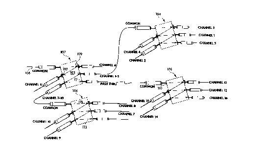
illustrated in Fig. 6 for a 16 channel system. Four WDMs are employed in a branch
cascading arrangement, wherein three of the WDMs 104-106 are connected in parallel
to the other WDM 107 which is, in turn, connected to a fiber-optic or other waveguide
trunk line 108 carrying the 16 channel multiplexed signal. The optical multiplexing
device of Fig. 6 is well suited to dense wavelength division multiplexing for a fiber-
optic telecommunication system. It will be appreciated, of course, that another optical
multiplexing device comparable to that illustrated in Fig. 6 would be advantageously
employed at one or more other locations along trunk line 108. The optical multiplexing
device of Fig. 6 is seen to employ several of the features discussed above in connection
with other embodiments. Specifically, interleaving is employed at each of the four
WDMs, such that post filters are used only at selected channel ports and not at other
channel ports. Compound interleaving is not employed in the embodiment of Fig. 6,
although it will be readily apparent to those skilled in the art in view of this disclosure,
especially the discussion of the embodiment of Fig. 4 above in which compound
interleaving is employed, that this feature also could be used in the 16 channel device of
Fig. 6. The WDM 107 is seen also to employ the drop cascade feature discussed above
in connection with Fig. 5. Specifically, a multi-channel end range is passed by channel
port 103 which sequentially follows channel port 109 at which a single adjacent
channel, channel 6, is removed. (Channel port 102 is seen to occur between channel
ports 109 and 103). Also notable is that such multi-channel signal passed to common
port 1 10 of WDM 105 comes from an optical port 1 11 of WOM 107 which is a
residual port. That is, optical port 111 is a non-wavelength selective optical port.
CA 02238606 1998-0~-2~
-
26
Optical port 113 at the end of light path 115 in WDM 106 is seen to be a non-
wavelength selective residual port to which no channel is assigned. It will be
recognized that an additional channel could be handled by the optical multiplexing
device of Fig. 6 at this port. It is also notable in connection with the WDM 107, that
removal of charmels 6 and 11 can be accomplished without unacceptable degrading of
the signal of adjacent channels, because each can be taken out from the multiplexed
signal using a single channel, narrowband filter. Employing a filter with a figure of
merit of at least about 40% to remove a single channel will result in good signal
isolation for the desired channel with advantageously low transparency to the adjacent
channels. Likewise, notwithstanding that the other three optical ports of WDM 107
pass multi-channel wavelength sub-ranges, the channels adjacent to such multi-channel
wavelength sub-ranges are not degraded because they have previously been removed.
The optical multiplexing device illustrated in Fig. 7 employs a WDM 52
constructed in accordance with the description provided in connection with the
embodiment of Fig. 1, above. In the embodiment of Fig. 7, however, each of the
optical ports of WDM 52 passes a multi-channel signal to another WDM. Thus, optical
port 30 passes a multi-channel signal via fiber-optic line 201 to the common port of
WDM 206. Similarly, channel port 42 of WDM 52 passes a multi-channel signal via
fiber-optic line 202 to the common port of WDM 207; channel port 18 passes a multi-
channel signal via fiber-optic line 205 to WDM 210; channel port 40 passes a multi-
channel signal via fiber-optic line 204 to WDM 209; and, finally, optical port 44 which
is a non-wavelength selective residual port, passes a multi-channel signal via fiber-
optic line 203 to WDM 208. Thus, each of the optical ports of WDM 52 passes a
multi-channel signal to one of a set of parallel WDMs which are optically coupled to
WDM 52. Each of the parallel cascaded WDMs has multiple optical ports including
multiple channel ports. Each of the optical ports of the parallel cascaded WDMs may,
in turn, pass a single channel or a wavelength sub-range comprising multiple channels.
It will be recognized that in the latter case a third and even fourth or subsequent tier of
WDMs may be cascaded together with those shown in Fig. 7 to achieve multiplexing of
even higher numbers of channels.
CA 02238606 1998-0~-2~
27
An optical multiplexing device 250 in accordance with an alternative
embodiment is illustrated in Fig. 8. The optical multiplexing device 250 is seen to be
mounted within an enclosed space 251 defined by housing 252. Preferably enclosedspace 251 is hermetically sealed by housing 252. The optical multiplexing devicecomprises a first WDM 254 having a common port 255, and a second WDM 256
having a common port 257. The common ports of the two WDMs are connected in
parallel to a red/blue beamsplitter 258. Beam splitter 258 has a common port 259which receives a multi-channel expanded beam optical signal from a trunkline 260 of a
fiber optic telecommunication system or other optical system employing a wavelength
division multiplexed signal. More specifically, trunkline 260 is seen to extend through
a wall of housing 252 to collimator 262 which directs the signal as an expanded beam
into beam splitter 258 at an angle suitable to establish a multi-bounce zig-zag light path
within the optical block 264 of beam splitter 258. In accordance with a significant
aspect of preferred embodiments in accordance with Fig. 8, a sequentially first channel
port 266 of beam splitter 258 removes a mid-channel, that is, a wavelength sub-range
which is intermediate the rem~ining "red" and "blue" portions of the multiplexedsignal. In the exemplary embodiment illustrated in Fig. 8, channel 8 is removed at first
channel port 266, with channels 1 through 7 then being removed at the next "bounce"
along the expanded beam light path 270, that is, at channel port 272. The rem~ining
signals are then passed by optionally unfiltered optical port 274. An optical filter 276
and a post-filter 278 are employed at channel port 266, since adjacent channels 7 and 9
may be present in the expanded beam at that point. The extracted signal corresponding
to channel 8 is then fed via waveguide 280, such as a fiber optic line, to an access port
282 passing through the wall of housing 252. Since adjacent channel 8 has been
removed prior to channel port 272, only a single optical filter 284 is used there. The
multi-channel signal carrying channels 1 through 7 is passed via waveguide 286 to
common port 255 of first WDM 254. Similarly, the multiplexed signal comprising
channels 9 through 16 is passed via waveguide 288 to common port 257 of the second
WDM 256. Each of the individual channel signals multiplexed by the two WDMs is
carried by a corresponding waveguide, preferably a fiber optic line, through a
corresponding access port in the outer wall of housing 252. Although not employed in
CA 02238606 1998-0~-2~
28
the particular embodiment illustrated in Fig. 8, those skilled in the art will recognize in
light of the disclosure above of other embodiments, that the first and second WDM in
the optical multiplexing device of Fig. 8 could advantageously employ interleaving of
the channels.
An optical multiplexing device in accordance with an alternative embodiment is
illustrated in Fig. 9. The optical multiplexing device of Fig. 9 comprises a first WDM
301 which is mounted within housing 303. A second WDM 302 is cascaded parallel
with WDM 301 from a passive coupler 305. The second WDM 302 is seen to be
mounted with separate housing 304. Passive coupler 305 is optically coupled to amulti-channel trunk line 307 of a fiber-optic telecommunication system employingdense wavelength division multiplexing. The signal from trunk line 307 is split by
passive coupler 305. Specifically, the entire 8 channel signal at partial strength is
carried by waveguide 308 to common port 309 of WDM 301, while the entire 8 channel
signal is carried at partial strength by waveguide 310 to common port 311 of WDM302. Preferably, the passive coupler 305, waveguides 308 and 310, and housings 303
and 304 containing, respectively, WDMs 301 and 302 along with associated
componentry, are all housed within an enclosure 314 defined by housing 315. It can be
seen that access ports are provided for feeding trunk line 307 to passive coupler 305,
and for carrying the signals associated with individual channels (or multi-channel
wavelength sub-ranges) from WDMs 301 and 302 out of housings 303 and 304, and
then out of housing 315.
Various suitable passive couplers are commercially available and will be
apparent to those skilled in the art in view of this disclosure. A 3 dB coupler may be
used, for example, to evenly split the signal strength between the two WDMs. Other
passive couplers may be used to unevenly split the signal strength, for example, 60/40,
70/30, etc. Passive couplers may also be employed in tiers, such that a three way, four
way or more split of the signal can be achieved. Preferably in all such alternative
arrangements, the one or more passive couplers along with the WDMs are mounted
within an enclosure defined by a housing corresponding to housing 315 of the
embodiment of Fig. 9. In certain preferred embodiments, the outer housing 315, or
CA 02238606 1998-0~-2
29
more preferably, the inner housings 303 and 304, or both, are sealed, e.g., hermetically
sealed.
It will be apparent from the above discussion that various additions and
modifications can be made to the optical multiple~ing devices described here in detail,
5 without departing from the true scope and spirit of this invention. All such
modifications and additions are intended to be co~-ered by the following claims.