Note: Descriptions are shown in the official language in which they were submitted.
CA 02238824 1998-05-27
W O 97/19727 PCT~US96/18985
MODULAR SEAT ASSEMBLY
RELATED APPLICATIONS
,.
This application claims priority to and all the benefits of co-pending U.S.
Provisional Patent Application Serial No. 60/007,548 which was filed on
November 27, 1995 and is entitled "Modular Vehicle Seat Assembly". This
application also claims priority to and all the benefits of co-pending U.S. Provisional
Patent Applic~tion Serial No. 60/016,775 which was filed on May 7, 1996 and is
entitled "I~ ed Modular Vehicle Seat Assembly". Still further, this application
also claims priority to and all the benefits of the following co-pending United States
Patent Applications: U.S. Serial No. 08/705,513, filed August 29, 1996 and entitled
"An Automotive Modular Seat Frame Assembly"; U.S. Serial No. 08/705,422, filed
August 29, 1996 and entitled "Automotive Seat back Recliner"; U.S. Serial
No. 08/705,420, filed August 29, 1996 and entitled "Automotive Seat back"; U.S.
Serial No. 08/705,424, filed August 29, 1996 and entitled "Self-~lignin~ and Self-
Docking Electrical Connector"; and U.S. Serial No. 08/705,512, filed August 29,
1996 and entitled "Rear Seat and Package Tray Sub Assembly."
TECHNICAL FIELD
The subiect invention relates to automotive seat assemblies and, more
spe~if1cally, to a modular se~at frame, seat back and recliner assembly, self-docking
electric~l connector and rear seat assembly.
BACKGROUND OF THE INVENTION
By way of background, vehicle front and rear seat assemblies typically
include a right and left seat assembly having a seat bottom portion, a pivotal seat
back, a seat track assembly and a center console or armrest assembly positioned
between the right and left seat assemblies. Typically, each of the co~ onellls
comprising the seat assemblies must be indepen-iPntly mounted in the vehicle, that
is, to the vehicle floor pan. The seat bottom and seat back are typically mounted to
a pair of seat tracks which must be then mounted to the vehicle floor pan for each
CA 02238824 1998-05-27
W O 97/19727 PCT~US96/18985
individual seat assembly. Similarly, the center console is commonly secured-
between the seat assemblies and mounted to the vehicle floor pan.
Additionally, the front seat assemblies for automobiles are typically desi nPd
for each model of an automobile and are only usable in that model. The seat
assembly for each model is fabricated from co".ponents spe~ifi~711y desi~nP~ forthat particular seat assembly and the seat assembly for opposite sides of the vehicle
frequently differ, somPtim~-s l~uiling the two seats to be in~t~711ed in the vehicle in
separate procedures.
There remains a need for an improved design which is fabricated of a
miniml1m of colllponents which are universally used in seats from model to model,
yet ret~7ining the flexibility to individually stylize the seats from model to model.
Att~n-3~nt to those design objectives is the requirement for a basic or universal seat
frame and seat back assembly.
It is also desirable to improve both the c~.l,roll and l)~lr~ll"ance of seatbelt1~ restraint systems by developing seat assemblies which have the seat belt resll~inl
systems mounted to the seat rather than the vehicle body. This improves comfort
and ~lr",llance of the r~ t system by m~ 7i.~g the seat belt anchor points
in fixed positions relative to the seat oc-;u~-l, regardless of the adjusted position
of the seat within the vehicle body.
It is also yet desirable to provide a seat back recliner m~rh~ni~m which
provides infinite degrees of rer1ining adj~l~tmPnt and r~ t~nce to movement in
response to impact forces.
Still further, P~1e~tr~ connectors for vehicle seat assemblies must meet a
variety of design criteri~. A most difficult situation p lesel ts itself where one desires
2~ to make a blind comle~ion, preferably by robotic ~Ci~t~nce~ for a wiring h~rnPs~
having multiple electric connectors between male and female t~rmin~l~os~ which
accounts for m~nl1f~rt11ring and in~t~ ti~n ~embly tolerances between the
members being electn~-~11y coupled and which will accommodate vibration and
consequently relative movement bt;~ween these lllt;lllb~l~ after electrical coupling and
final assembly, i.e. during use.
Many of the seat assembly's parts require an electrical connection to operate
any number of electrical devices located therein. Typically, the electrical devices
CA 02238824 1998-05-27
W O 97/19727 PCTAJS96/18985
are mounted to the a~)pr~pliale seat frame. F.l~tric~l devices commonly found-
within the seat ~eeemblies may include seat adj--etm~nt m~rh~ni~m~, lumbar support
merh~ni~me, headrest adjustmP-nt mech~niem~, a seat bottom heating mech~ni.em,
or other similar devices. Fl~tric~l devices commonly found within the center
,, S console or a"~ L assembly can include armrest adjlletm~-nt mP~h~niem~, cigarette
lighters, various inl1ir~tin~ lights, map lights, cellular phones, stereo components,
or other similar devices. Each of these electrical devices has numerous input wires
which are individually mounted to a terminal box. Specifically, each input wire is
welded or otherwise affixed to a corresponding pin. As can be appre~i~t~l, the
number of L~,l,inal boxes increases as the nulllbel of electric~l devices utilized on
the seat assemblies increases. The vehicle frame has col,c~ollding l~l,l,inal boxes
wherein each terminal box has a number of sockets located therein. During
inet~ tinn, the pins must be aligned with the sockets in order to create an Plectriç~l
connection. Accordingly, the inet~ tion of the seat assemblies is subst~nti~lly
burdened when a great number of electrical devices are utili7~1 In other words,
an in~t~ller must first correctly connect each terminal box eYten-ling from eachçle~tric~l device to the corresponding terminal box on the vehicle frame. After the
in~t~ller ensures that an electrical connection has been created, the particular part
of the seat assembly is then in~t~11~1,
Finally, rear seat assemblies typically include a seat bottom and a seat back.
The seat back comprises a right and a left seating surface and a center portion
positioned between the right and left seating sllrf~ s. The right and left seating
s~lrf~f~es and the center portion of the seat back are usually one unitary piece, i.e.,
they form a bench-type seat back. The right and left seating s-lrf~(es are conr~,l".ed
into numerous shapes, sizes, or configurations ~lepen~ling upon the vehicle model.
An a.n~ may be pivotally disposed within the center portion for selective use byan occ~ll. Purther, stationary or adjustable headrests may be located at the top- surface of the seat back. A number of mounting brackets extend downwardly from
the seat back for mounting engagement with a vehicle floor pan. These brackets
may comprise a pivot hinge which allows the seat back to pivot forwardly toward
the seat bottom. This may be desirable if a user wishes to extend the floor of a rear
trunk co,l,~a,l",ent.
CA 02238824 l998-05-27
W O 97/19727 PCT~US96/18985
~imilarly, the seat bottom comprises a right and left seating surface and a~
center portion positioned between the right and left seating surfaces. The right and
left seating sllrf~- es and the center portion of the seat bottom are also one unitary
piece. The right and left seating s~lrf~es may also be contoured into any numberS of shapes, sizes, or configurations. A number of mounting brackets extend from
the seat bottom portion for mounting engagement with the seat back and/or the
vehicle floor pan.
A package tray, having a curved rear periphery and a s~bs~ lly flat front
face, is typically mounted to the vehicle behind the rear seat assembly. The
package tray usually retains numerous devices such as audio speakers, audio
headphone jacks, first aid kits, rear tail lights, seat belt mounting plates, and seat
belt retractors. The package tray may also be covered by a trim cover m~tPri~l.
Specifie~lly, the rear periphery of the package tray is mounted below a rear
window at the juncture of the rear window and the rear trunk co.npa.l,l,ent,
whereby the package tray covers the opening between the rear of the seat back and
the trunk co"lp~l,llent. The package tray mounts to the juncture by means of
numerous ~tt~rhmPnt devices. The tray usually includes a number of brackets or
mounting holes located within the flat front face. During in~t~ tion, the package
tray is mounted to the vehicle and the nP~P~ry devices are then installed in thetray. Some time after the tray is mounted, the s~al~te components of the rear seat
assembly are installed within the vehicle. The seat back typically latches to the
brackets Pytenflin~ from the package tray or is bolted via the mounting holes to the
package tray. Accordingly, the current manuf~-*lnng procedure l~ uilt;S at leasttwo (2) separate and distinct steps for mounting the package tray and the seat back
within the vehicle. Therefore, it is also desirable to provide a unitary rear seat
assembly and p~.k~e tray for in.ct~ tion within the vehicle with a single mounting
procedure.
SUMMARY OF THE INVENTION AND ADVANTAGES
The subject invention provides a seat frame assembly for a vehicle
comprising a pair of fixed rails e~en-ling fore and aft and being laterally spaced
from one another, with brackets ~tt~rhP~l to the fixed rails for ~tt~-hment to a
CA 02238824 1998-05-27
WO 97/19727 PCT/lJS96/18985
vehicle body, a slide rail ~u~olled by each of the fixed rails provides fore and aft-
movement relative to the fixed rails. A pair of front and rear crossbeams
inl~l~;o~ ect the slide rails for ~u~O~ g all of the rem~inin~ col-lLx>.lents of a seat
~u~polled totally on the crosshe~m~.
The subject invention also provides for an automotive seat back assembly
comprising a pair of spaced upright members each having lower ends and upper
ends and a cross-member eYten~1ing between the upper ends with mounting means
at the lower ends for mounting to a seat frame. A shoulder belt housing extends
upwardly be~we~.l the upright members from below the cross-member to a distal end
disposed above the cross-ll-e-llb~r.
The subject invention also provides for a seat assembly comprising a seat
frame and a seat back including a pair of spaced upright members each having lower
ends and upper ends with mounting means at the lower ends for mounting the seat
back to the seat frame for pivotal movement relative to the seat frame; and a control
. "P~l~ni~m for controlling the pivotal movement inclurling a cylinder and a first coil
spring wound around and in gripping engagement with the cylinder, the first coilspring having first and second ends extenrlin~ tangentially from the cylinder, and an
actuator for moving the second end relative to the first end for unwinding the first
coil spring in a clockwise direction from the gripping engagement to allow the
pivotal movement of the seat back relative to the seat frame, the actuator incl~ ing
a ç~m~h~ft in parallel relationship to the cylinder and Png~ging the second end, the
c~m~h~ft being rotatably ~u~olL~d by the seat back for rotary movement bc;lw~
a set position with the coil spring in the gripping engagement with the cylinder to
prevent the pivotal movement of the seat back relative to the seat frame and a
release position having moved the second end in an unwinding direction to unwindthe coil spring from the gripping engagement to allow the pivotal movement of the
seat back relative to the seat frame.
The subject invention further provides a self-~ligning and self-docking
Pl~Pctric~l connector assembly comprising a frame member and at least one
electrically operated component ~u~o~led by the frame mPmher. A first electricalconnector box is secured to the frame member. The ele~triç~lly operated colllponent
is elect~ically connected to the first box. The first box may include one or more
CA 02238824 1998-05-27
W O 97119727 PCT~US96/18985
electlical co~lnecLol~, each being reciliently biased in the hol;;,...l~;.l and vertical-
planes to accommodate m~nllf~cturin~ tolerances during blind assembly and constant
vibrations during use. An ~t~chm~ont member is disposed on the frame member for
~tt~hin~ the frame mto.mbe.r and the first box to a support structure. A guide
member guides the first box into ~ nmPnt with a complementary second electrical
c-~nn~ctor box on the support structure having complementary guide means for theelectric~l connectors per se, for establishing an electrical connection with theelectrically operated component.
Finally, an automotive rear seat assembly comprises a seat back having a top
and a bottom for supporting the back of an occ~lp~nt A package tray extends fromthe top of the seat back to an outer periphery. A rotational connection is disposed
between the tray and the top of the seat back, whereby the rear seat assembly may
be shipped with the tray subst~nti~lly overlying the seat back and in~t~lle~ in a
vehicle by rotating the tray relative to the seat back to a position transverse to the
seat back.
BRIEF DESCR~PTION OF THE DRAVVINGS
Figure 1 is a perspective view of the interior of an automobile showing a
rear seat assembly in combination with the front seat assembly of the subject
invention;
Figure 2 is a perspective view of the support colllponents of the front seat
assembly employing the subiect invention;
Figure 3 is an exploded perspective view of one oc~ nt seat of the front
seat assembly of the subject invention;
Figure 4 is a fragmentary side view of the seat assembly of the subject
invention;
Figure 5 is a perspective view, partially broken away and in cross-section,
of the occup~nt ~u~olling co.l,~ ent of the subiect seat assembly;
Figure 6 is an exploded yel~e~ e view of the seat back of the subject
invention;
Figure 7 is a pc~ e view of the cover of the shoulder belt housing and
shoulder belt employed in the seat back of the subject invention;
CA 02238824 1998-05-27
W O 97/19727 PCT~US96/1898~
Figure 8 is a fr~gm~nt~ry ~el~eeLive view of the recliner m~h~ni~m of the
subject invention;
Figure 9 is a fr~gm~nt~ry cross-sectional view talcen along line 9-9 of
Figure 8;
Figure 10 is a perspective view of an automotive seat assembly and a vehicle
floor pan utili7:ing a self-~lignin~ and self-docking electrical connector;
Figure 11 is a fr~gm~,nt~ry p~l~e~ e view of the seat assembly and the
floor pan;
- Figure 12 is a partial cross-sectional view of a first electrical connector box
and a second electrie~l connector box talcen along line 12-12 of Figure 10;
Figure 13 is a partial cross-sectional view of the first and second boxes in
an engaged position;
Figure 14 is a partial cross-sectional view of an ~ltem~tive embodiment of
the first and second boxes;
Figure 15 is a partial cross-sectional view of another alternative embodiment
of the first and second boxes;
Figure 16 is a plan view of an ~lt~ tive configuration of the pins of the
first box;
Figure 17 is a plan view of another ~ltern~tive configuration of the pins;
Figure 18 is a plan view of yet another ~ltern~tive configuration of the pins;
Figure 19 is a partial cross-sectional view of an alternative embodiment
showing a rear seat assembly incol~old~ g the first and second boxes;
Figure 20 is a partial cross-sectional view of another ~lt~,rn~tive embodiment
showing the rear seat assembly incol~u~dling the first and second boxes;
Figure 21 is a partial cross-sectional view of an ~ltern~tive embodiment
showing an instrument panel incol~uldLing the first and second boxes;
Figure 22 is a partially exploded perspective view of an alternative
embodiment showing an automotive door assembly incorporating the first and
second boxes;
Figure 23 is a perspective view of an ~1tern~tive embodiment showing
modular office ful-lilul~ incorporating the first and second boxes;
CA 02238824 1998-05-27
W O 97/19727 PCTAUS96/18985
Figure 24 is a perspective view of a rear seat assembly according to the
subject invention;
Figure 25 is a cross-sectional view taken along line 25-25 of Figure 24;
Figure 26 is a view similar to Figure 25 but showing a package tray pivoting
S toward a seat back in a partially overlying position; ,.
Figure 27 is a perspective view of the rear seat and package tray in a
shipping con-1ition;
Figure 28 is an enlarged perspective view of a rotational connection between
the seat back and package tray;
Figure 29 is a cross-sectional view of the rotational connection of Figure 28;
Figure 30 is an enlarged perspective view of an alternative embodiment of
the rotational connection;
Figure 31 is a cross-sectional view of the rotational connection of Figure 30;
Figure 32 is an enlarged ~l~e~ e view of another alternative embodiment
of the rotational connecti{m;
Figure 33 is an enlar.ged perspective view of yet another a~ ali~e
embodiment of the rot~tir~n~l connection;
Figure 34 is a cross-sectional view of the rotational connection of Figure 33;
Figure 35 is a fr~gmPnt~ry ~ e view of the underside of the package
tray of Figure 24 and a vehicle frame;
Figure 36 is a cross-sectional view of an attachment device between the
package tray and the vehicle frame of Figure 35;
Figure 37 is a fr~gmPnt~ry perspective view of an alternative embo-limP.nt
of the ~tt~chmPnt device;
Figure 38 is a cross-sectional view of the ~tt~-hmP.nt device of Figure 37;
Figure 39 is a fr~gmPnt~ry perspective view of another alternative
embodiment of the ~tt~hment device;
Figure 40 is a cross-sectional view of the ~tt~hm~nt device of Figure 39;
Figure 41 is a fr~ment~ry perspective view of yet another alternative
embodiment of the ~tt~t~hmP.nt device;
Figure 42 is a cross-sectional view of the att~rhmPnt device of Figure 41;
CA 02238824 1998-05-27
W O 97/19727 PCT~US96/1898
Figure 43 is a fr~gmPnt~ ~e;li~e view of yet another ~l~prn~tive
embodiment of the ~tt~hm~nt device;
Figure 44 is a cross-sectional view of the ~tt~rhmPnt device of Figure 43;
Figure 45 is a perspective view of a single motor drive mPrh~ni~m of the
S seat assembly; and
Figure 46 is an exploded view of a tr~ncmi~ion for the single motor drive
mP~h~ni~m .
I)ETAILED DESCRIPTION OF THE PREFERR~D EMBODIMENT
Referring to the figures, wherein like nllmer~l~ indicate like or col-~s~onding
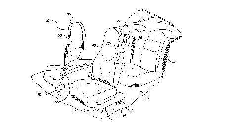
parts throughout the several views, a front seat assembly is generally shown at 10.
The assembly 10 is to be inet~lle l as a unit in a vehicle 12 in front of a rear seat
assembly 14.
The seat assembly 10 includes a pair of fixed rails 16 eYten-ling fore and aft
and being laterally spaced across the vehicle 12 from one another. A plurality of
lS brackets 18 and 20 are ~tt~rhPA by rivets 22, or the equivalent, to the fixed rails 16
for ~tt~ hmPnt to a vehicle body 12. Preferably, the brackets 18 include an L-shaped
slot which latch onto hooks 19 which extend from the vehicle 12. A slide rail 24 is
sul)~olled by each of the fixed rails 16 for fore and aft movement relative to the
fixed rails 16. One of the fixed 16 and slide 24 rails being C-shaped ch~nnPl~ with
the other of the fixed 16 and slide 24 rails being slidably disposed in the C-shaped
ch~nnP,l More srecific~lly, the fixed rails 16 comprise the C-shaped ch~nnels having
openings 26 which face one another and the slide rails 24 are slidably disposed in
the C-shaped ~h~nn~ls d~o-fining the fixed rails 16. Although not shown, roller or ball
bearings may support the slide rails 24 in the fixed rails 16. A pair of front 28 and
rear 30 cross-beams in~o~ ect the slide rails 24 for ~ul-p~ g all the rem~ining
components of a first seat su~o,led totally on the cross-beams 28 and 30. The
- cross-beams 28 and 30 extend through the openings 26 in the C-shaped ch~nn
~lefining the fixed rails 16 with the ends thereof ~tt~r-hYl to the slide rails 24, which
are disposed inside the C-shaped çh~nn~l~
A pair of seat back flanges 32 support a seat back 34. The rear cross beam
30 has an irregular cross section, i.e., triangular, as best in shown in phantom lines
CA 02238824 1998-05-27
W O 97/19727 PCT~US96/18985
in Figure 4. The cross-beams 28 and 30 are hollow tubes and provide torsional
strength, particularly for the seat back flanges 32. 13ach of the seat back flanges 32
has an irregular or triangular opening 36 comI limPnt~ry to and surrounding the rear
cross beam 30 for su~ Ling the seat back 34 on the rear cross beam 30.
A~r~,~ia~e pivot pins 38 inler~nl ect the seat back 34 and the flanges 32 for
re~ linin~ movement of the seat back 34.
A SU1J~U1 L sheet 40 extends between and is ~u~olled by the cross-beams 28
and 30. The support sheet 40 may be attached to the cross-beams 28 and 30 by
f~ten~rs or spot welding, or the equivalent. The support sheet 40 is cupped at the
rear to extend around the rear cross beam 30 and has a platform at the front edge.
A seat pan 42 is disposed above the support sheet 40 for ~u~olliilg an
occupant over the recess 43. A rear bladder 44 and a front bladder 46 are disposed
between the sheet 40 and the pan 42 for raising and lowering the r~ecli~re back
and front of the pan 42 relative to the sheet 40 for adjusting the vertical positioning
of the seat. As will be appreci~ted, an applo~id~ pump and electrical drive motor
with associated controls will be included in the seat assembly to inflate and deflate
the respective bladders 44 and 46.
A pair of front linkages 48 intel~,-llect the pan 42 and the slide rails 24 for
guiding the raising and lowering movement of the front of the pan 40. Two sets of
rear linkages 50 i.lL~rconllect the pan 42 and the slide rails 24 for guiding, raising
and lowering movement of the rear of the pan 42. More srerific~lly, a pair of front
linkages 48 are rotatably connected to brackets 52 which are, in turn, secured to the
pan 42 and are in~l~o~ ed by a rod 54. The rod 54 is non-rotatably supported
to linkages 48 so that the linkages 48 rotate in unison and to keep both sides of the
seat at the same vertical height. The rod 54 is rotatably supported by and above the
slide rails 24. In similar fashion, one of the rear links of each pair 50 is connected
to the pan 42 by bracket 56 with the other link of each pair 50 secured to a rod 58,
which is, in turn, rotatably supported by and between the slide rails 24 whereby the
rear of the seat moves up and down in unison from side to side.
The front seat ~e-mhly 10 inçlndes second pairs of fixed 16 and slide 24
rails and inleç~o~ c~ing cross-beams 28 and 30 defining a second seat. The
brackets therefor include frame members 20 inlerconl-ectin~ the inside slide rails 24
CA 02238824 1998-05-27
W O 97/19727 PCTAUS96/18985
of the first and second seat assemblies for clefining a front seat assembly 10 which-
may be in~t~llecl into a vehicle 12 as one unit. In other words, a robot could move
the entire fini~hed seat assembly 10 through the door opening in the vehicle 12 body
and precisely connect the brackets 18 to the hooks 19 and the frame members 20 to
S similar connPcting devices.
In accoldance with the co~ollellt philosophy, a stylized seat bottom trim 60
is ~u~pol~d on the pan 42. In a similar fashion, a stylized back trim 62 is supported
on the seat back frame 34. The trim CO".pO~ S 60 and 62 are secured in place by
aL~r~liate quick f~tenP-rs (not shown), e.g., screws. Different trim co,-,pollents 60
and 62 may be utilized for dirrt;~ -t color vehicles and for dirrelenl models ofvehicles.
An occup~nt support means 64 is disposed in the recess 43 of the pan 42 for
cushioning ~u~po,l of an oc~;u~ t. More specifically, the oc~;upallt support
means 64 comprises a flexible woven sheet su~pe~clPd across the recess by rings 66
and provides a soft support for the occupant.
The outermost coopeldtillg pairs of the fixed 16 and slide 24 rails are
disposed laterally of or beside the bottom trim 60 and a cover 68 is disposed over
the laterally disposed pair of fixed 16 and slide 24 rails. A center console 70 is
~u~olL~d on the frame members 20 between the first and second seat assemblies.
The automotive seat back 34 which compn~es a pair of spaced upright
members 40' each having lower ends rotatably supported on the pivot pins 38. In
other words, the pivot pins 38 define mounting means at the lower end of the
upright members 40' for mounting the seat back 34 to the flanges 32 of the seat
frame. The upright members 40' have upper ends interconnPcted by a cross-
member 42' ~t.on-ling between the upper ends.
A shoulder belt housing 44' extends upwardly between the upright
members 40' from below the cross-member 42' to a distal end 46' disposed above
the cross-member 42'. The shoulder belt housing 44' defines a belt opening 48' for
guid;ng a shoulder belt 50'. The opening 48' is disposed vertically above one of the
upright members 40' for positioning the shoulder belt 50' over the shoulder of the
occupant. As shown, the belt opening 48' is positioned outside the area between the
upright members 40'.
CA 02238824 1998-0~-27
W O 97/19727 PCT~US96/18985
The seat back 34 incllldes criss-crossing truss elements 52' interconnecting -
the upright members 40' and the housing 44'. The truss el~-m~nt~ 52' suspend thehousing 44' within the periphery of the seat back as defined by the upright
members 40' and the cross-member 42'. Plefe~dbly, the upright members 40' and
the cross-member 42' and the truss PlPmPnt~ 52' and the housing 44' are all
int~grAlly formed of a homogenous material, such as being die cast of m~gneSillm.
The housing 44' includes a lower end disposed midway between the upright
membçrs 40' and curves upwardly and outwardly to the distal end 46' on one side
of the seat back 34. As seen in Figures 6 and 7, the housing 44' includes a coffin
portion defined by side walls 54' and a bottom 56' with the side walls 54' beingintegral with the truss members 52' and the upper member 42'. Tke housing 44'
further comprises a cover 58' di~pos~l over and in sealing engagement with the side
walls 54'. As shown, the cover 58' is disposed on the front face of the seat back 34
but the positions of the cover 58' and the bottom 56' may be reversed so that the
cover 58' faces the rear seat assembly 14. The cover 58' incl~des lateral pads 60'
for receiving screws which threadedly engage holes in the truss members 52' or
bosses to secure the cover over the side walls 54' of the coffin portion. The
cover 58' is rotated 180~ from the position shown in Figure 7 to the position shown
in Figure 6.
The cover 58' of the housing 44' incl~ es a guideway 62' for the shoulder
belt 50'. The opening 48' is el--ng~t~l along an axis disposed at an acute angle to
the upper cross-member 42' for accommodating the diagonal extension of a shoulder
belt 50' over the shoulder of the occupant. To accommodate the angled exit of the
seat belt S0' from the opening 48', the guideway 62' has a colllpoulld curve to
prevent the edges of the shoulder belt 50' from g~th~ring in the PYt~n~ion thereof
in the lower guideway 62' and lhlougll the curved guideway 62' to the opening 48'.
In other words, the colllpoulld curve is analogous to a banked or ramped race track.
The upright members 40', the upper member 42', the truss members 52',
and the side walls 54' are all rectangular in cross-section with the major axes
thereof extenrling from front to back of the seat back 34, i.e., they are plate-like
with their edges facing the front and rear of the seat back 34. The major axis of the
rectangular cross-section of the truss members 52' is less than the major axis of the
CA 02238824 1998-OF7-27
WO 97/19727 PCT/US96/18985
13
rectangular cross-section of the upright members 40', i.e., the truss members 52'-
are rece~se l below the outward edges of the upright members 40'.
The shoulder belt SOt disposed in the housing includes a reel 64' for
reccilin~ and uncoiling the shoulder belt 50'. The reel 64' is Att~ch~i to the
cover 58' by bracket and bolt assembly 66'.
A trim co.ll~ollent 68' is disposed over the seat back 34, the component 68'
having an opening 70' therein and the distal end 46' of the housing 44' eYten-l~through the opening 70'. The co~ Jonent 68' encomr~ses the entire seat back 34
but may cover only the front of the seat back 34. As illl-~t~f~d, there are right and
left hand seat backs 34, but to reduce colllpol~ellts the seat backs may be identical
with the distal ends 46' being on the same side in both of the front seats.
The seat back flanges 32 mount the seat back 34 to the seat frame for pivotal
movement relative to the seat frame and a control mech~nism is incl~de~ for
controlling the pivotal movement of the seat back 34. The control m~h~ni~m
inclllcles a cylinder 54" and a first coil spring 56" wound around and in gripping
engagement with the cylinder 54". The cylinder 54" is non-rotatably secured to the
seat frame by being welded or otherwise secured to the flanges 32. The first coil
spring 56" has first 58" and second 60" ends eYt~-n-ling tangentially from the
cylinder 54". A second coil spring 62" is wound around and in gripping
engagement with the cylinder 54" and, likewise, has third 64" and fourth 66" ends
l-YteM11ing tangentially from the cylinder 54". Each of the coils 56" and 62" isrectangular in cross-section with one of the sides or edges thereof being in thegripping frictional engagement with the cylinder 54".
The seat back 34 defines or ~ sents slots 68" and the first 58" and third 64"
ends are retained in the slots 68". More specifi~lly, washers 70" are welded to the
first ends 58" to prevent the first ends 58" from being pulled through the associated
slot 68". Rec~llce the third ends 64" of the other coils are disposed at an angle in
the slots 68", they are welded directly to the sides of the slots 68". AlL~ ati~rely,
straps or loops could extend across the slots 68" with washers likewise welded to
the third ends 64" and retained in the slots 68" thereby. Therefore, the first 58"
and third 64" ends are secured to the seat back 34.
CA 02238824 l998-0~-27
WO 97/19727 PCT/US96/18985
14
As one skilled in the art can appreciate, the second 60" and fourth 66" ends-
could be retained in slots 68" with the first 58" and third 64" ends continuously to
extend tangentially from the cylinder 54". In addition, the first 58", second 60",
third 64", and fourth 66" do not n~s~- ;ly have to extend t~n~n~i~lly in the same
direction, i.e., they may be transverse to one another. To that end, the first 58" and
third 64" ends of the first 56" and second 62" coil springs could be retained inslots 68" located in the rear cross-beams 30. Hence the first 58" and second 68"ends of the coil spring project in opposite directions.
If one of the ends 58", 60", 64", 66" of the coil springs 66", 62" is secured
to a structure other than the seat back 34 the cylinder 54" maybe rotatably secured
to the seat back 34 wherein the seat back 34 and cylinder 54" rotate as one unit.
An actuator is incllld~1 for moving the second end 60" relative to the first
end 58" for unwinding the first coil spring 56" in a clockwise direction from the
gripping engagement with the cylinder 54" to allow the pivotal movement of the seat
back 34 relative to the seat frame and for moving the fourth end 66" relative to the
third end 64" for unwinding the second coil spring 62" in a counter-clockwise
direction from the gripping engagement with the cylinder 54" to allow the pivotal
movement of the seat back relative to the seat frame. As will be a~yr~ r~l, the
clockwise movement and counter-clockwise movement depend upon which side is
viewed and are terms of relative definition and not limiting as one may be
substituted for the other.
The actuator includes a c~m~h~ft 72 in parallel relationship to the
cylinder 54" and eng~ging the second 60" and fourth 66" ends, the c~m~h~ft 72
being rotatably ~UypOl led by the upright members 40' of the seat back 34 for rotary
movement between a set position with the coils 56" and 62" in gripping engagement
with the cylinder 54" to prevent the pivotal movement of the seat back relative to
the seat frame and a release position in which the second 60" and fourth 66" ends
have been moved in an unwinding direction to unwind the coils 56" and 62" from
the gripping engagement to allow the pivotal movement of the seat back 34 relative
to the seat frame. The c~m~h~ft 72 includes cam lobes in the form of grooves 74 for
moving the second 60" and fourth 66" ends between the set and release positions
CA 02238824 1998-05-27
W O 97tl9727 PCT~US96/18985
An arm 76 extends radially from the c~m~h~ft 72 and a m~nn~11y ~t-l~te~le release~
cord 78 is connected to the arm 76 for rotating the ç~meh~ft 72.
A biasing spring 80 reacts belween the seat back 34 and a shaft 82 fixed to
the flanges 32 for urging the seat back 34 to pivot relative to the seat frame when
the coils 56" and 62" are in the release position.
As stated above, the first 56" and second 62" coil springs are in constant
engagement with the cylinder 54" when the seat back 34 is in a rest position. During
excessive acceleration or deceleration, i.e., a rear end collision or a frontal
collision, the coil springs 56", 62" will autom~tir~lly grip the cylinder 54" and
reduce the frontal or .cal~v~d movement of the seat back 34. Spec-ific~lly, in a rear
end collision the seat back 34 will have a tendency to move backward which will
pull the third end 64" of the second coil spring 62" backward, thereby progressively
gripping the cylinder 54". In other words, as the tendency for the seat back 34 to
move ~ealw~d increases the gripping force applied to the cylinder 54" increases.Conversely, in a frontal collision the seat back 34 will have a tendency to moveforward which will pull the first end 58" of the coil spring 56" forward and
progressively grip the cylinder 54". Accordingly, the subject invention also provides
an added safety feature to the seat back 34.
Referring to Figure l0, at least one e1~ctric~11y operated col.,ponent 22"' is
~u~u,Led by the seat frame 20"'. The e1ectric~11y operated component 22"' is a
seat track adj--etment mP~ h~niem Other e1Pctric~11y operated con-~; onents commonly
found within the seat assemblies may include seat adjuetm~nt mPrh~ni~m~, lumbar
support me~h~nieme, headrest adjustm~nt m.~h~niem~, a seat bottom heating
m~ch~niem, or other similar devices. There may also be electrically operated
components found within the center console assembly, which can include al.llr
adjusLmGIlt mech~nieme, cigarette lighters, various in(li~ting lights, map lights,
cellular phones, stereo co--~po~ents, or other similar devices. Each of these
electric~11y opel~ted co",~onents 22"' has numerous input wires 24"' ext~ntiing
thelGrlvlll. Any nu",ber or all of these electrically operated components 22"' could
be ~u~ol~ed by the frame member 20"' without deviating from the scope of the
subject invention.
CA 02238824 1998-05-27
W O 97/19727 PCT~US96/18985
16
A first electrical connector box 26"' is secured to the seat frame 20"'.-
More specifi~lly, the first box 26"'is secured to the seat frame 20"' underneaththe center console assembly. The electrically opc~d~d co",ponent 22"' iS
electrically connect~ to the first box 26"'. Sper-ific~lly, each input wire 24"'eYten-ling from the ele~tric~lly operated co",,~onent 22"' iS connected to a
~lle~ollding lead wire 28"' eYt~ntlin~ from the first box 26"'. As can be
a~ A, any number or all of the Ple~triç~lly operated components 22"'
discussed above could be connlocted to the first box 26"' and the first box 26"'could be secured to any part of the seat frame 20"'. An ~tt~-~.hment member,
generally depicted at 30"',is mounted on the seat frame 20"' for ~tt~ehing the seat
frame 20"' and the first box 26"' to a support structure. The support structure is
comprised of a tunnel section 38"' and a vehicle floor pan 40"' of a vehicle (not
shown). The ~tt~,hmPnt member 30"' comprises two oulw~rdly exten-ling brackets
32"' each having an L-shaped slot 34"'. Specific~lly, the brackets 32"' extend
outwardly and downwardly from the seat frame 20"' whereby the L-shaped slot
34"' engages a locator pin 36"' protruding from the tunnel section 38"' of the
vehicle floor pan 40"'. During in~t~ tion of the seat assembly 10"', the seat
frame 20"' may slide along the floor pan 40"' with a range equal to the size of the
L-shaped slot 34"'.
Referring spe~-ific~lly to Figures 12 and 13, the first box 26'" includes an
interior chamber 42"' defined by the first box 26"'. The chamber 42"' has a top
surface 44"' and a plurality of side walls 46"' e,~ten~ing from the top surface 44'"
to an inwardly projecting flange 48"' wherein the distal end of the flange 48"'
defines the circumference of an opening 50"'. A mounting place 52"' is disposed
within the chamber 42"' and ~up~o~led for limited flo~tin~ movement within the
chamber 42"' of the first box 26"'. The flanges 48"' retain the mounting place
52"' within the chamber 42"'. A plurality of recessed cavities 54'" are located
within the top surface 44"' of the chamber 42"' and the mounting plate 52'". A
plurality of resilient eleme,nt~, generally depicted at 56"', ~u~olls the mounting
plate 52"' in the first box 26"' for both lateral and in and out movement relative
to the first box 26"'. Specifically, the resilient ~lem~nt~ 56'" are coiled springs
58"' that engage the recessed cavities 54"' within the top surface 44"' and the
CA 02238824 1998-05-27
W O 97/19727 PCTrUS96/18985
17
mounting plate 52"'. The resilient elements 56"', however, can be of any-
configuration or design so long as the mounting plate 52"' is continuously biased
toward the opening 50"' within the first box 26"' and is permitted lateral flo~ting
movement between the side walls 46"'. An annular seal 60"' is affixPA to the first
box 26"' and surrounds the opening 50"' within the Gh~mher 42"'. The free space
on the lateral orientation between member 52"' and box side walls 46" ' is sllfflcient
to allow flc~tin~, self-locating, movement accommodating the m~m~f~tllring and
assembly tolerances involved. Similarly, the free space in the vertical/in and out
orient~tion between member 52'" and box top wall 44"' allows the same flo~ting
accommo-l~ting these tolerances as well as vibrations during use, and it allows for
the pins 68"' to be fully retracted within the box 26"' to accommodate sliding the
box 26"' into an electrical connecticn with box 64"'.
A guide member, generally shown at 62"', is inch~ Pfl for guiding the first
box 26' ' ' into ~ nmPnt with a comrlemPnt~ry second electrical connector box 64" '
on the tunnel section 38"' of the vehicle floor pan 40"', which in turn establishes
an electrical connection with the electrically operated co"~one.-t 22"' within the
vehicle. During in~t~ tion, the guide member 62"' moves the mounting plate
52"' laterally for ~lignmPnt with the second box 64"' on the vehicle. The annular
seat 60"' provides sealing engagement between the first 26"' and second 64"'
boxes.
The first box 26"' also comprises of a plurality of electrical connectors,
generally depicted at 66"'. The connectors 66"' comprise at least one male 68"'
and female 70" ' element wherein the çlPmPnt~ 68" ', 70" ' define the guide member
62"'. More specifically, the male elements 68"' are solid pins 68"' having
parabolic front surfaces 72"' and the female çlPment~ 70"' are cylin-lric~l recessed
cavities 70"'. The pins 68"' may be made of brass or any other electrical
con~l~lcting m~tPri~l. The pins 68"' are enc~ed within the mounting plate 52"' of
the first box 26"' and the recessed cavities 70"' are çn~ed within the second box
64"'. A cylin-lric~l ch~mfer 74"' extends downwardly toward a circular cylinder
76"' which defines the circumference of each recessed cavity 70"'. The ~ metPr
of the circular cylinder 76"' is only slightly larger than the ~ m~t~r of the pins
68"' to define a slip fit. A bendable contact plate 78"' is disposed within each
CA 02238824 1998-05-27
W O 97/19727 PCT~US96/18985
18
recessed cavity 70" ' directly below each circular cylinder 76" ' . The contact plates
78"' can be made of a beryllium copper alloy (BeCo) or other suitable electric~lcon(lucting m~teT~l . The chamfers 74" ' located around the outermost perimeter of
the outermost recessed cavities 70"' may be larger and have a shallower slope than
S the challlrel~ 74"' located between these outermost cavities 70"'. In other words,
they might be elliptical to accommodate larger man~f~ctnring and/or assembly
toler~nces along that particular axis. In any event, the length of each cavity 70'"
will ,l~rereldbly be constant and render equal clo~king suL~L)olL for all pins. The
chamfers 74"' f~-~,ilit~t~, a self~ ning feature and thus must be shaped to define an
entrance to the cavity accommodating the m~nllf~ctllring and assembly toler~nc~es
in that lateral plane and along any axis. The circular cylinders 76'", given their
relative rli~meters and length, f~rilit~t~ a self-docking feature. In other words,
during in~t~ tion the pins 68"' slide along the cha---rt:l~ 74"' as the seat assembly
10"' is being positioned. The pins 68"' then slide down the ch~,.,re.~ 74"' and
into the circular cylinders 76"' which retain the pins 68"' into position. Hence,
the pins 68"' autom~tir-~lly align and dock themselves within the circular cylinders
76"'. The parabolic front surfaces 72"' of the pins 68"' are now in electrical
engagement with the contact plates 78"' of the recessed cavities 70"'.
F.l~Ctri~l taps 80"' extend into the mounting plate 52"' and abut the pins
68"' wherein the contact plates 78"', the pins 68"', and the taps 80"' are all
electric~l con~lucting elem.qnt~. Each contact plate 78'" and tap 80"' has the
corresponding lead wires 28"' extPn~1ing thelerr ~l--. Sperifir~lly, the lead wires
28"' e~tçn-lin,~ from the contact plates 78"' are c~nnec,t~l to an electrical power
source (not shown) and the lead wires 28"' extending from the taps 80"' are
connect~l to the electrically operated component 22"'. Note that this arrangement
could be reversed with the contact plates 78"' connected to the electnc~lly operated
co~ onent 22"' and the taps 80"' connPcteA to the electrical power source without
deviating from the scope of the subject invention. However, the ~.er~,led designfor electrical conn~cti-n has the power source connected to the female element 70"'
or contact plate 78"', and the load or electrically operated colllpullent 22"'
conntoct~ to the male element 68"' or taps 80"' and pins 68"'. This design
prevents any inadvertent short ci~ g during in~t~ tion. As can be appreciated,
CA 02238824 1998-05-27
W O 97/19727 PCT~US96/1898
19
if the power source was connectPcl to the pins 68"' on the first box 26"', the pins
68"' could accid~nt~lly contact a ground on the vehicle which would short circuit
the power source. With the power source conne&t~d to the contact plates 78"'
located within the r~cessed cavities 70"' there is only a minim~l chance of an
~çid~nt~l short circuit.
The male 68"' and female 70"' elemP-nt.~ can be arranged in any fashion,
however, experimPnt~ have shown that the best configuration is when the elements68" ', 70" ' are generally offset from one another in a transverse direction. In other
words, the elements 68"', 70"' are in a non-symmPtr1c layout. Examples of non-
unirolll' configurations are shown in the following Figures. Figure 11 shows thepins 68"' and the lc~cessed cavities 70"' arranged in three offset parallel rows and
Figure 16 shows an alternative embodiment of the pins 68"' arranged in two offset
parallel rows. Figure 17 shows another ~lt~rn~tive embodiment wherein the pins
68"' are arranged in a circular matrix and Figure 18 shows yet another ~ltern~tive
lS embodiment wherein the pins 68"' are arranged in an arrowhead shape. As is
a~l~alellt, the configuration of the recessed cavities 70" ' must conform to the exact
configuration of the pins 68"'. Further, the optimum configuration will depend
upon the in~t~ tion l~uirelllents and electrical devices to be lltili7ed.
An alternative embodiment is shown in Figure 14 wherein like numerals
increased by one hundred in~ t.o like or cc,ll~*,onding parts. A first electrical
connector box 126"' incluc~es an interior chamber 142"' defined by the first box126"'. The chamber 142"' has a top surface 144"' and a plurality of side walls
146"' eYt~nfling from the top surface 144"' to an inwardly projecting flange 148"'
wherein the distal end of the flange 148"' defines the cil~;ulllftreilce of an opening
150"'. A mounting plate 152"' is disposed within the chamber 142"' and
supported for limited flo~ting movement within the chamber 142"' of the ~lrst box
126"'. A biasing plate 182"' slidably engages the mounting plate 152"' for
~ ~ul~polling the mounting plate 152"' in the first box 126"'. The flanges 148"' abut
the mounting plate 152"' and retain the mounting plate 152"' and biasing plate
182"' within the chamber 142" '. A plurality of recessed cavities 154" ' are located
within the top surface 144"' of the chamber 142"' and the biasing plate 182"'. Aplurality of resilient elenlent~, generally depicted at 156'", supports the mounting
CA 02238824 1998-0~-27
WO 97/19727 PCT/US96/18985
152"' and biasing 182"' plates in the first box 126"' for both lateral and in and out-
movement relatîve to the first box 126"'. Specific~lly, the resilient elements 156"'
are coiled springs 158"' that engage the recessed cavities 154"' within the top
surface 144"' of the first box 126"' and the biasing plate 184"'. The resilient
elemPnt~ 156"', however, can be of any configuration or design so long as the
mounting plate 152"' and biasing plate 182"' are continuously biased toward the
opening 150"' within the first box 126"'. An annular seal 160"' iS affixed to the
first box 126"' and surrounds the opening 150"' within the chamber 142"'.
A guide member, generally shown at 162"',is included for guiding the fiMt
box 126"' into ~lignm~nt with a complement~ry second electric~l connector box
164"' on a tunnel section 138"' of the vehicle floor pan 40"', which in turn
establishes an electrical connection with the elPct~iç~lly operated co~ onent 22"'
within the vehicle. During in~t~ tion, the guide member 162"' moves the
~nounling plate 152"' and biasing plate 182"' laterally for ~lignmt-nt with the
second box 164'" on the vehicle. The annular seal 160"' provides sealing
engagement between the first 126"' and second 164"' boxes.
The first box 126"' also comprises of a plurality of electric~l connectors,
generally depicted at 166"'. The connectors 166"' comprise at least one male
168"' and female 170"' e1P-m~nt wherein the elements 168"', 170"' define the
guide member 162"'. More specifically, the male elements 168"' are solid pins
168"' having parabolic front surfaces 172"' and the female elements 170"' are
cylin-lric~l recessed cavities 170'''. The pins 168"' may be made of brass or any
other electrically con~1ucting m~tP~i~l. The pins 168"' are ~qnC~ec~ within the
mounting plate 152"' of the first box 126'" and the recessed cavities 170"' are
2~ enc~ed within the second box 164"'. A cylin~ l chamfer 174'" extends
downwardly toward a circular cylinder 176"' which defines the circumference of
each recçssed cavity 170"'. The ~ meter of the circular cylinder 176"' is largerthan the ~ meter of the pins 168"'. A bendable contact plate 178'" iS disposed
within each rece~sed cavity 170'" directly below each circular cylinder 176"'. The
contact plates 178'" can be made of a beryllium copper alloy (BeCo) or other
suitable electrically conducting material. The chamfers 174"' located around theperimeter of the recessed cavities 170"' are larger and have a shallower slope than
CA 02238824 1998-05-27
W O 97/19727 PCT~US96/18985
21
the chamfers 174''' located between the recessed cavities 170'''. The chamfers-
174"' f~ilit~t~ the self-~ligning feature and the circular cylinders 176"' f~'ilit~tP
the self-docking feature. In other words, during in~t~ tinn the pins 168"' slidealong the chamfers 174"' as the seat assembly 10"' is being positioned. The pins168"' then slide down the chamfers 174"' and into the circular cylinders 176"'
which retain the pins 168"' into position. Hence, the pins 168"' autom~tiç~lly
align and dock thPtn~plves within the circular cylinders 176"'. The parabolic front
surfaces 172'" of the pins 168"' are now in electrical engagement with the contact
plates 178"' of the rècessed cavities 170"'.
Electrical taps 180" ' extend into the mounting plate 152" ' and abut the pins
168"' wherein the contact plates 178"', the pins 168"', and the taps 180"' are all
elPctric~l condl1ctin~ elements. Each contact plate 178"' and tap 180"' has a
colles~ollding lead wire 128"' extending ~lelcrlulll. A plurality of apertures 184"'
are defined within the biasing plate 182"' wherein the lead wires 128"' extend
through the al,c;llufes 184"' in the biasing plate 182"'. The mounting plate 152"'
slides along the biasing plate 182"' having a range equal to the diameter of theal~el~u~es 184"' located within the biasing plate 182"'. The lead wires 128"'
PYten-ling from the contact plates 178"' are connected to an P1ectril ~1 power source
~not shown) and the lead wires 128"' eYtpn~ling from the taps 180"' are connected
to the electrically operated co"-ponent 22"'. Note that this arrangement could be
reversed with the contact plates 178"' connected to the ele~tric~lly operated
component 22"' and the taps 180"' connP~t~d to the electrical power source.
However, as ~ c~ ~i above, the ~-~felled design for electrical connection has the
power source conne~ted to the female e1em~qnt 170"' or contact plate 178"', and
the load or electrically operated component 22"' connected to the male e4m~nt
168"' or taps 180"' and pins 168"'. This design prevents any inadvertent short
Cileui~ing during in~t~ tion. As discussed above and shown in the Figures, the
~ male 168"' and female 170"' elements can be arranged in any fashion.
Another ~ltern~tive embodiment is shown in Figure lS wherein like numerals
increased by two hundred indicate like or collG~ollding parts. A first e1e~tri~
connector box 226"' includes an interior chamber 242"' defined by the first box
226"'. The chamber 242"' has a top surface 244"' and a plurality of side walls
CA 02238824 1998-05-27
W O 97/19727 PCTAUS96/18985
22
246"' extPn~ing from the top surface 244"' to an inwardly projecting flange 248"'-
wherein the distal end of the flange 248"' defines the circumference of an opening
250"'. A mounting plate 252'" iS partially disposed within the cl,an~ber 242"' and
supported for limited flo~tin~ movement within the chamber 242"' of the first box
226"'. A ridge 286"' extends from the top of the mounting plate 252"' and
engages the flanges 248"' of the first box 226"' wherein the rem~inder of the
mounting plate 252"' protrudes through the opening 250"'.
A guide member, generally shown at 262"',isincllldP~l for guiding the first
box 226"' into ~lignm~nt with a comp4m~nt~ry second electrical connector box
0 264"' on a tunnel section 238"' of the vehicle floor pan 40"', which in turn
establishes an electrical connection with the P~ tric~1ty operated co-"ponent 22"'
within the vehicle. During in~ tinn, the guide member 262'" moves the
mounting plate 252"' laterally for ~ nm~nt with the second box 264"' on the
vehicle.
A plurality of hollow posts 288"' extend from the mounting plate 152"'
wherein the posts 288"' define the guide member 262"'. The posts 288"' do not
have any electrical ch~r~r-tPristics and taper at their distal end thereof. A plurality
of resilient ~lem~nt~, generally ~iP.pictP~l at 256"', supports the mounting plate
252"' in the first box 226"' for both lateral and in and out movement relative to
the first box 226"'. Specifically, the resilient elements 256"' are coiled springs
258"' that are disposed within the posts 288"' for supporting the mounting plate252"'. The resilient elements 256"', however, can be of any configuration or
design so long as the mounting plate 252"' iS continuously biased toward the
opening 250'" within the first box 226"'. A nu.l.bel of holes 290"' are defined
within the second box 264"' wherein each post 288"' extends outwardly beyond themounting plate 252"' of the first box 226"' and engages the co.l~onding hole
290"' in the second box 264"'. E~ch of the holes 290"' includes a chamfer 274"'
ext~n-ling downwardly thereto. The chamfers 274"' located around the pPrimeter
of the holes 290'" are larger and have a shallower slope than the chamfers 274"'located on the inside surface of the holes 290"'. The chamfers 274"' f~-'.ilit~t~. the
self-~ligning feature.
CA 02238824 1998-05-27
WO 97/19727 PCT~US96~1898~;
23
The first box 226"' also comprises of a plurality of elPctric~l connectors,-
generally depicted at 266"'. The connectors 266"' comprise at least one male
268"' and female 270"' el~mPnt of smaller ~ mP~ters than the posts 288"'. More
specifically, the male elements 268"' are hollow pins 268"' having curved front
S surfaces 292"' and the female elPmPnt~ 270"' are cylin-lriç~l recessed cavities
270"'. The pins 268"' are en~ P~l within the mounting plate 252"' of the first
box 226"' and the recessed cavities 270"' are Pnr~C~I within the second box
264"'. A small circular cylinder 276"', which defines the circumference of each
rece~ed cavity 270"', is located above a bendable contact plate 278"'. The
circular cylinders 276"' f~rilit~tp the self-docking feature and have a rli~metpr
slightly larger than the fli~mPtPr of the pins 268'". During in~t~ tion, the posts
288"' slide along the ch~mfers 274'" as the seat ~embly 10"' is being positioned.
The posts 288" ' then slide down the chamfers 274" ' and fall within the holes 290" '
in the second box 264"'. Simultaneously, the pins 268"' are aligned with the
circular cylinders 276"' of the recessed cavity 270"' wherein the pins 268"' extend
into the circular cylinders 276"' and the curved front s-lrf~es 292"' electrically
engage the contact plates 278"'.
The contact plates 278"' and the pins 268"' are electriç~l conducting
elemPn~ that each has a co"~sl)onding lead wire 228"' PYtPn~ling thel~rlu-,-. A
plurality of parabolic çh~nnPl~ 294"' are disposed above each collesponding pin
268"' within the mounting plate 252"'. These ch~nnel~ 294"' create an inner
cavity for the lead wires 228"' to tap into the pins 268"'. The lead wires 228"'extP~1in~ from the contact plates 278"' are connected to an electric~1 power source
(not shown) and the lead wires 228"' ~xten-ling from the pins 268"' are connPGtP~
to the electrically operated component 22"'. Note that this ~rr~n~emPnt could bereversed with the contact plates 278"' connected to the çl~triczllly o~e.~ted
component 22"' and the pins 268"' connected to the Plectriç~l power source.
However, as discussed above, the pl~ft;l-ed design for electrical connection has the
power source connect~P~ to the female elemPnt 270"' or contact plate 278"', and
the load or electriç~lly operated component 22"' is connectPd to the male elempnt
268"' or pins 268"'. This design prevents any inadvertent short circuit during
CA 02238824 1998-05-27
W O 97/19727 PCT~US96/18985
24
in~t~ tion. As discussed above and shown in the Figures, the male 268"' and-
female 270"' elements can be arranged in any fashion.
As depicted in Figure 15, the posts 268"' are ~tt~Ch~d to the mounting plate
252"' outside the male 268"' and female 270"' ç~ mP-nts. An annular seal 260"'
surrounds the eleme-nt~ 268"' of the first box 226"' and the elem~nt~ 270"' of the
second box 264"' for providing sealing engagement between the first 226'" and
second 264"' boxes. Accordingly, the seat 260"' is disposed between the posts
288"' and the PkPmPnt~ 268"', 270'''.
The pins 268"' disclosed in this embodiment are thinner and longer than the
pins 68"', 168"' disclosed in Figures 12, 13, and 14. These smaller pins 268"'
can be grouped in greater numbers which create a greater density of P.lement~
268"', 270"'. As appreciated by those skilled in the art, a key factor that controls
the m~nit---le of an electrical current is the amount of contact area between the pins
andcontactplates. Accordingly, thepins68"', 168"' disclosedin Figures 12, 13,
and 14 are of greater surface area which affords them a greater contact area andallows a greater current to pass ther~lhlvugh. The pins 268"' disclosed in Figure
lS have a smaller surface area which reduces the contact area and lowers the
m~gnit~l~le of the current that can pass th~lc;lhl~oug~l. Hence, these dirr~.c;,.~
embo-limPMt~ will be used for dirrt;~ t applic~tion~. For eY~mplP, an electn~llyoperated component 22" ' that has a large number of input wires 24" ' and requires
a relatively low current would utilize the pin design ~ closP~l in Figure 15. Note
that the dirrer~l pin designs could be utilized in conjunction with each other
wh~lein larger solid pins and smaller hollow pins are mounted to the same mounting
plate.
Figures 19 and 20 disclose an alternative embodiment wherein an automotive
rear seat assembly 82"' comprising a seat bottom 84"', a seat back 86"', and a
package tray 88"' all utilize the common frame member (not shown). The frame
member disclosed in Figures 19 and 20 is an automotive seat frame known to thoseskilled in the art. At least one electri~lly operated component 22"' is supported
by the seat frame. Electrically operated co"lpol-ellts 22"' commonly found within
rear seat assemblies 82"' may include audio speakers, audio headphone jacks, rear
tail lights, seat adjll~tment mech~ni~mc, lumbar support mP~h~ni~m~, headrest
CA 02238824 1998-05-27
WO 97/19727 PCT~US96/~8~85
adjustment mtorh~ni~m~, a seat bottom heating m~h~ni~m, or other similar devices. -
The first electrical connector box 26"' is secured to the seat frame with the
elertriç~lly operated coml.oilent 22"' conn~cted thereto. The seat frame and first
box 26"' are in turn ~,tt~h~1 to a support structure. The support structure shown
in Figures 19 and 20 is COmI ri.~l of a wheel well 90"' and a trunk sill 92"'. As
shown in Figure 19, the complenlent~ry second ~le~tric~l connector box 64"' is
mounted to the wheel well 90"'. Hence, during inct~ ,ti~n of the rear seat
assembly 82"', the first box 26"' autom~t~ lly aligns with the second box 64"' to
form an electrical connection with the electrically operated component 22'''. Asshown in Figure 20, compl~-m~nt~ry second electrical connector boxes 64"' are
mounted to both the wheel well 90'" and the trunk sill 92"'. During in~t~ tion,
the first box 26" ' on the package tray 88" ' autom~tir~lly aligns with the second box
64"' on the trunk sill 92'" to forrn the e1~triç~l connection. Then the seat back
86"' is pivoted d~w~w~dly wherein the first box 26''' on the seat back 86'''
automatically aligns with the second box 64''' on the wheel well 90"' which forms
an additional elP~c~ric~l colme~;Lion.
3?igure 21 discloses an ~ltern~tive embodiment wh~ l~in an automotive
instrument panel 94"' incorporates the first electrical connector box 26"'. At least
oneele,ctriç~lly~eldledco,~ olle.lt22"'is~u~oll~;dbythein~L,ulllentpanel94"'.
Electrically operated co"-llonellts 22"' commonly found within instrument panels94"' may include audio speakers, audio receivers, air bag assemblies, instrumentlights, clocks or other similar devices. Each e1ectric~lly operated co,l,~onent 22"'
is conneete~ to the first box 26"'. The in~L~ llt panel 94"' and first box 26"'
are in turn ~tt~rhed to a support structure. The support structure shown in Figure
21 is an interior vehicle frame 96"' which has the complementary second electrical
connector box 64"' mounted thereto. Hence, during in~t~ t;on of the instrument
panel 94"', the first box 26"' autom~tic~lly aligns with the second box 64"' to
~ form an electric~l connection with the electrically operated component(s) 22"'.
Figure 22 discloses an alternative embodiment wherein an automotive door
assembly 98"' incorporates the first electric~l connectcr box 26"'. At least oneelectrically operated co~-ponelll 22"' is supported by the door assembly 98"'.
Electrically operated components 22"' commonly found within door assemblies
CA 02238824 l998-05-27
WO 97/19727 PCT~US96/18985
26
98"' may include audio speakers, window actuators, door locks, remote entry-
mec.h~ni~m~, or other similar devices. Each electrically operated component 22"'is connectP~I to the first box 26"'. The door assembly 98"' and first box 26"' are
in turn attached to a support structure. The support structure shown in Figure 22
is an interior door jam 100"' which has the complementary second electrical
connector box 64"' mounted thereto. The first box 26"'iS mounted to a door
hinge 102"' via a bracket 104"'. Hence, during in~t~ tion of the door ~eml~ly
98"', the hinge 102"'is bolted to the door jam 100"' wherein the first box 26"'
autom~tic~lly aligns with the second box 64"' to form an electrical connection with
the electrically operated component(s) 22"'.
Figure 23 discloses an alternative embodiment wherein numerous parts of
modular office cubicle 106" ' incol~ol~te the first electrical connector box 26"' and
the compli.)~ .y second electrical connector box 64"'. At least one electrtç~llyu~d~d co~llponent 22"'iS ~u~ol~d by the office cubicle 106"'. E~ectric~ly
operated co,llponents 22"' commonly found within modular office cubicles 106"'
may include audio speakers, lights, electrical power plugs, clocks or other similar
devices. The first PlP~ctri~l connector box 26"' iS secured to one part of the
mod~ r of fice cubicle 106" ' with the electrie~lly operated co~ onent 22" '
connPctecl thereto. The second box 64"' is ~tt~hP~l to a support structure or
second part of the modular office cubicle 106"'. During in.~t~ tion of the modular
office cubicle 106"', the first box 26"' autom~ti~lly aligns with the second box64"' to form an electrical connection with the electrically operated component(s)
22'''.
Referring to Figures 45 and 46, a single motor drive m~h~ni.~m is generally
shown at 66iY for providing multi-axis adj~-stmP.nt of the seat and p~P.nger seating
position. The motor drive m~och~ni.sm 66iV is comprised of an electronic motor 68iV
and a tr~n.cmi~ion 70iV. The motor 68iV incl~ldes an input drive shaft 72iV with a
worm gear 74iV ~lxed to the distal end thereof. As best shown in Figure 46, the
tr~n~mi~.~ion 70iV includes a pair of (:~po~ ly rotating worm gear wheels 76iV, 78iV
that are in permanent engagement with the worm gea~ 74iv. Each worm gear wheel
76iV, 78iV includes a toothed inner cavity 80iv that is capable of receiving a spur gear
82iV, 84iV. Each spur gear 82iV, 84iV is anchored to a spring loaded, solenoid ~ct~l~tPA
CA 02238824 1998-05-27
W O 97119727 PCT~US96/18985
27
shaft 86iV~ 88iV. A center gear g~v is also provided for selective engagement by the-
spur gears 82iV~ 84iV. In operation, by movement of the shafts 86iV~ 88iV, whichmoves the spur gears 82iV~ 84iV into and out of engagement with the worm gear
wheels 76iV, 78iV and the center gear 9~V, a single electronic motor 68iV is capable
of ~ctu~ting a six (6) axis seat assembly.
Referring to Figures 24 through 44 an automotive rear seat assembly is
generally shown at lOV. The rear seat assembly 10V comprises a bench-type seat
back 12V having a top 14v and a bottom 16V for supporting the back of an occuL~ t
(not shown) and a bench-type seat bottom (not shown) for ~u~o~ g the bottom of
the occupanl. Specific~lly, the seat back 12V comprises a right 18V and a left 20V
seating surface and a center portion 22V positioned between the right 1 8v and left 20V
seating surfaces. The right 18V and left 20V seating surfaces and the center portion
22V of the seat back 12V are one unitary piece. The right 18V and left 20V seating
surfaces may be contou-cd into any number of shapes, sizes, or configurations toaccommodate various vehicle models. An armrest 24v is pivotafly disposed within
the center portion 22V of the seat back 12V for selective use by the occupant.
Further, stationary or adjustable headrests 26V are located at the top 14v Of the seat
back 12V for use by the OC~ t In addition, other accessulies may be added to
the rear seat assembly lOV, i.e., an integr~l child seat (not shown), a pair of side
impact air bags (not shown), integraf storage co~ ll,ents (not shown), etc.
A package tray 28V PYtPnds from the top 14v of the seat back 12V to an outer
periphery 30V. The p~c~ge tray 28V has a top surface 32V and a bottom surface 34V.
A fabric cover may extend over the top surface 32v of the tray 28V to improve the
aesthetics of the tray 28V. In addition, the top surface 32v may house a rear tail light
36V, a number of speaker grills 38V, a first aid kit (not shown), or any other
a~ ~.;ale device. A rotational colme~;lion, generally depicted at 40V, is located
between the tray 28V and the top 14v of the seat back 12V. As shown in Figures 25,
26, and 27, the rear seat assembly 10V may be shipped with the tray 28V
subst~nti~tfy overlying the seat back 12V (Figure 27) and in~t~lle~ in a vehicle (not
shown) ~y rotating the tray 28V relative to the seat back 12V to a position transverse
to the seat back 12V (Figure 25). In other words, during in~t~ tinn of the rear seat
assembly 10V into the vehicle, the seat back 12V, package tray 28V, and all other seat
-
CA 02238824 1998-05-27
W O 97/19727 PCT~US96/18985
28
back accessolies included in the rear seat assembly 10V are installed as a unitary-
piece.
The seat back 12V inrludes a back frame 42v and cushioning m~trri~l 44v
~u~ol~d by the back frame 42V. The cushioning m~teri~l 44v may be covered by
S a fabric and/or leather trim cover 45V, The rotational connP~ti~-n 40v il~ter~o~ ects
the back frame 42v and the tray 28V. A number of mounting brackets 46v extend
dow"w~Lrdly from the back frame 42v for mounting engagement with a vehicle floorpan (not shown).
One embodiment of the rotational conn~tion 40v is shown in Figures 25 and
26 wherein the rotational connection 40V comprises a piano hinge 48v pivotally
connected belw~n the back frame 42v and the tray 28V. The piano hinge 48v
compri.~s two flat plates 50v each having cylinc~ric~1 sections locat~d at a distal end
thereof. The cylin~iriç~l sec~icn~ are intermeshed with each other with a pin
e~cten-ling thel~Llllough, whereby the two plates 50v are pivotally interconnected.
The piano hinge 48v may extend along the entire top 14v of the seat back 12V or any
section thereof so long as the hinge 48v provides adequate support for the tray 28V.
Another embodiment of the rotational conne~;Lion 40V is shown in Figures 28
and 29 wherein the rotational connectil~n 40v comprises a pocket, generally depicted
at 52V, and a bulbous projection, generally depicted at 54V. The bulbous projection
54v comprises a cylin(lric~l section 56v and the pocket 52v comprises a clip 58vwh~lein the cylindrical section 56v is disposed in the clip 58V. A pair of support
legs 60V extends from the tray 28V and ~u~oll~ the cylin-~ri~i section 56v
thel~ebeL~eel~. The clip 58v includes an inwardly curved hook 62V and is fixedlysecured to the back frame 42V. More sperifir~lly, the cylin-lrir~l section 56v extends
from the tray 28V and is disposed within the curved hook 62V protruding from theback frame 42V, whereby the tray 28V is pivotally secured to the back frame 42Y.As shown in Figure 29, the support legs 60V are angled downwardly from the tray
28V to ensure constant eng~çm~nt with the curved hook 62V when the tray 28V is
rotated transverse to the seat back 12V. As can be a~~ rA, the ~ul)pc~ll legs 60V
and the cylindrical section 56v could extend from the back frame 42v with the clip
58v secured to the tray 28V without deviating from the scope of the subject invention.
CA 02238824 1998-05-27
W~ 97J19727 PCTAUS96/~898
29
An ~ re embodiment of the rotational collnectic)n 40v is shown in-
Figures 30 and 31 which is similar to the rotational connection 4Qv of Figures 28
and 29 wherein like numerals intli~t~. like or coll~;~onding parts. The rotational
conn.octi~n 40V comprises a pocket 52v and a bulbous projection 54V rotatably
disposed in the pocket 52V. The bulbous projection 54v comprises a cylindrical
section 56v and the pocket 52v comprises a clip 58V. A pair of support legs 60V
extend from the back frame 42V and support the cylin-lric,~l section 56V
therebetween. The clip 58v comprises at least two jaws 64V, 66V which retain thecylindrical section 56v therein. More spe~,ific~lly, the cylin-lri~ l section 56v extends
downwardly from the back frame 42v and is disposed within three jaws 64V, 66V
protruding from the tray 28V, whereby the tray 28V is pivotally secured to the back
frame 42V. As shown in Figure 30, the three jaws 64Y, 66V are configured with two
upwardly curved outside jaws 64v and one downwardly curved center jaw 66V. The
jaws 64V, 66V could be configured in any manner so long as they adequately retain
the cylin~1ric~l section 56v therein. A dc,wllw~~dly angled support plate 68V
intercom~ects the jaws 64V, 66V to the tray 28V. As can be appreci~t~d, the support
legs 60V and the cylin-lric~l section 56v could extend from the tray 28V with the clip
58v secured to the back frame 42v without deviating from the scope of the subject
mvenhon.
Yet another embodiment of the rotat,ional connection 40v is shown in Figure
32 wherein the rotational connection 40v comprises a plurality of overlapping legs
74v, 76v each having a bore 70v eYt~n~ling lhe~ ough. A pin 72Y passes lhl~ugh
the bores 70v which inlerconnects the legs 74v, 76v to form a hinge whereby the legs
74v, 76v rotate about the pin 72V. As depicted in Figure 32, two outside legs 74v
extend from the tray 28V and one center leg 76v extends from the back frame 42V.The center leg 76V fits within the two outside legs 74v such that the bores 70v are
aligned with each other. As is a~al~nl to those skilled in the art, there may be any
number of legs 74v, 76v eyto-n~ling from the tray 28V or the back frame 42V so long
as a hinge can be formed.
An additional embodiment of the rotational connection 40v is shown in
Figures 33 and 34 wherein the rotational connection 40v comprises a m~teri~l 78vaffixed at one end to the tray 28V and at the other end to the back frame 42V.
CA 02238824 1998-05-27
W O 97/19727 PCT~US96/1898
Specifically, the m~tp~ri~l 78v is adhered to a flange 80V eYt~nfling from the tray 28V
at one end and adhered to an ~tt~chmPnt bracket 82V at the other end. The
~tt~chment bracket 82V in turn is mounted to the back frame 42v via a screw 84V.The m~t.o.ri~l 78v may be made of any flexible m~teri~l such as woven cloth, rubber,
or the like so long as the m~t~ri~l 78v can bend to provide a pivotal connPctinnbetween the tray 28V and the seat back 42V.
The bottom surface 34v of the package tray 28V is shown in greater detail in
Figure 35. Also shown in Figure 35 is a fr~gment~ry view of a vehicle frame 86V.The tray 28V defines a number of open cavities gOv, 92v which can house audio
speakers of various sizes or other a~n)p,iale devices. Specific~lly shown in Figure
35 are two 6 X 9 audio speakers 88V housed in a pair of outside cavities gOv wherein
a center cavity 92v has support beams 94v eYt~qnding ther~LlLr~ugh. Each audio
speaker 88V in~ es electrical leads 96v with connectors 98v for colln~ctic n to a first
box 100V of a wiring harness located on the tray 28V. A second or corresponding
box 102V is located on the vehicle frame 86V for engagement with the first box 100V
when the tray 28V is in.~t~ d The rear tail light 36v is also ~u~polled by the tray
28V and inchldes electrical leads 96v with connectors 98v for connection to the first
box 100V of the wiring harness on the tray 28V. The bulbous projection 54V shownin Figures 28 and 29 and the legs 74v shown in Figure 32 are shown attached to the
2Q tray 28V as purely l~r~se~ ti~e of the rotational connection 40V. As can be
appreciated any number of the rotational connections 40v ~ c,lose~ could be affixed
to the tray 28V. Further, the package tray 28V may be shaped in any manner and
house any number of devices without deviating from the scope of the subject
invention.
Attachment members, generally depicted at 104V, are located along the outer
peli~hel,y 30V of the tray 28V for ~tt~ ment to the vehicle frame 86V. Two
embo~iim~,nt.c of the ~tt~-~.hm~.nt members 104V are shown in Figure 3~. The first
embodiment is a plurality of hook and loop f~tp,n~-,rs 106V, 108V located along the
outer periphery 30v of the tlay 28V. The hook and loop f~tt-n~rs 106Y, 108V
comprise a hook section 106V and a loop section 108V which are glued, adhered, or
otherwise affixed to the tray 28V and to the vehicle ~rame 86V. Either the hook
section 106V or the loop section 108V may be affixed to the tray 28V wherein the
,
CA 02238824 1998-05-27
W O 97/19727 PCT~US96J18985
c~llcs~ollding hook section 106V or loop section 108V is affilxed to the vehicle frame
86V. The second embodiment is a plurality of oL lwardly projecting fingers generally
depicted at llOV.
A cross-sectional view of the ouLw~dly projecting fingers 110V is also shown
in Figure 36. An ~tt~rhm~nt plate 112V is locked within the tray 28V whereby thefingers 110V extend from the ~tt~ m~nt plate 112V. Sl?ecifit~-~lly, the fingers 110V
are round retainer pegs 1 14v that extend dow,lw~rdly and outwardly in a
subst~nti~lly acute angle from the tray 28V. The retainer pegs 114V engage a
~;o~le~ullding aperture 116V located within the vehicle frame 86V when the tray 28V
lû is in~t~ A in the vehicle (Figure 36). A foam strip 118V is mounted along the outer
periphery 30V of the tray 28V outside the distal end of the retainer pegs 1 14v which
provides additional support for the outer periphery 30v of the tray 28V.
An al~l,laLive embodiment of the oLIlwardly projecting fingers 110V is shown
in Figures 37 and 38 which is similar to the outwardly projecting fingers llOV of
Figures 35 and 36. The outwardly projecting fingers llOV comprise a number of
L-shaped fingers 120V that include sloping front surf~ces 122V. Specifically, the L-
shaped fingers 120V have a long leg 124V exten-ling downwardly and subs~nti~lly
perpendicular from the tray 28V. A short leg 126V extends ou~w~dly from the longleg 124V in a subst~nti~lly parallel direction to the tray 28V. The L-shaped fingers
120V engage the corresponding a~elLul~ 116V located within the vehicle frame 86Vwhen the tray 28V is in~t~ d in the vehicle (Figure 38).
~et another embodiment of the ~tt~(~hm~nt members 104V is shown in Figures
39 and 40 wherein the ~tt~chm.ont members 104V comprise a plurality of cantilevered
hooks 128V affixed to the tray 28V. Each cantilevered hook 128V has a first end 130V
which is bent to coope~aLe with an abutment 132V in the tray 28V. Specifi~lly, the
first end 130V is bolted or otherwise ~tt~ched to the abutment 132V. Each
cantilevered hook 128V also incl~ldes an upwardly bent second end 134V, whereby
the upwardly bent second ends 134v extend through the co~lk~c,nding ap~llule 116V
in the vehicle frame 86V when the tray 28V is in~t~ d in the vehicle (Figure 40).
- 30 These upwardly bent second ends 134V engage the inside surface of the vehicle
frame 86V which prevents any upward movement of the tray 28V.
CA 02238824 1998-05-27
W O 97/19727 PCTrUS96/18985
Another embo-liment of the att~rllmP,nt members 104V is shown in Figures,
41 and 42 wherein the ~tt~chm~nt members 104V comprise a plurality of snap-in
fa~tenP,rs which are generally depicted at 136V. The snap-in fa~teners 136V each have
a top bead 138V and a bottom bead 140V with a circular ridge 142V sel~au~ g the two
S beads 138V, 14()V. The bottom bead 140V is split into at least two sides whereby the
sides can move with resect to each other. The top bead 138V of the snap-in fa~tPnPrs
136V engages an ape ~ure 144v located within the tray 28V. Sperifie~lly, the top bead
138V extends partially through the ap~llule 144v and the ridge 142V abuts the bottom
surface 34v of the tray 28V. The bottom bead 140V of the snap-in fa~tençrs 136V
engages the corresponding ap~lur~s 116V in the vehicle frame 86V when the tray 28V
is in~t~lled in the vehicle.
An allelllalive embodiment of the snap-in f~tenPrs 136V is shown in Figures
43 and 44 which is similar to the snap-in fa~t~nP,rs 136V of Figures 41 and 42. A
downwardly projecting flange 146V extends from the tray 28V wherein the snap-in
fa~tenPrs 136V have V-shaped sides 148V and engage the downwardly projecting
flange 146V. Sperifi~lly, a pair of interior clasps 150V engages the flange 146V and
retains the V-shaped snap-in f~cte,nçr 136V in position. The V-shaped snap-in
fa~tençrs 136V also engage the collc;~nding apellu-~s 116V in the vehicle frame 86V
when the tray 28V is in~t~ll~l in the vehicle (Figure 44).
The invention has been described in an illustrative manner, and it is to be
understood that the terminology which has been used is intçntled to be in the nature
of words of description rather than of limit~tion.
Obviously, many mo~lifie~tinns and variations to the present invention are
possible in light of the above teachings. It is lhererol, to be understood that within
the scope of the appended Claims wherein reference numPral~ are merely for
convenience and are not to be in any way limiting the invention may be practicedotherwise than as specifîc~lly described.