Language selection

Search

Patent 2239312 Summary

Third-party information liability

Some of the information on this Web page has been provided by external sources. The Government of Canada is not responsible for the accuracy, reliability or currency of the information supplied by external sources. Users wishing to rely upon this information should consult directly with the source of the information. Content provided by external sources is not subject to official languages, privacy and accessibility requirements.

Claims and Abstract availability

Any discrepancies in the text and image of the Claims and Abstract are due to differing posting times. Text of the Claims and Abstract are posted:

  • At the time the application is open to public inspection;
  • At the time of issue of the patent (grant).
(12) Patent Application: (11) CA 2239312
(54) English Title: APPARATUS FOR ASSEMBLING OF ANGLE PLATES ON THE FLANGES OF VENTILATION DUCTS
(54) French Title: APPAREIL D'ASSEMBLAGE DE PLAQUES D'ANGLE SUR LES BRIDES DE CONDUITS DE VENTILATION
Status: Deemed Abandoned and Beyond the Period of Reinstatement - Pending Response to Notice of Disregarded Communication
Bibliographic Data
(51) International Patent Classification (IPC):
  • B23P 19/04 (2006.01)
  • E04F 17/04 (2006.01)
  • F16L 23/14 (2006.01)
(72) Inventors :
  • KACZOROWSKI, WALTER (Poland)
(73) Owners :
  • WALTER KACZOROWSKI
(71) Applicants :
  • WALTER KACZOROWSKI (Poland)
(74) Agent: BORDEN LADNER GERVAIS LLP
(74) Associate agent:
(45) Issued:
(86) PCT Filing Date: 1996-03-29
(87) Open to Public Inspection: 1997-07-17
Examination requested: 1998-09-02
Availability of licence: N/A
Dedicated to the Public: N/A
(25) Language of filing: English

Patent Cooperation Treaty (PCT): Yes
(86) PCT Filing Number: PCT/PL1996/000006
(87) International Publication Number: WO 1997025179
(85) National Entry: 1998-06-02

(30) Application Priority Data:
Application No. Country/Territory Date
P.312175 (Poland) 1996-01-08

Abstracts

English Abstract


The subject of this invention is an apparatus for assembling of angle plates
on the flanges of ventilation ducts. The apparatus comprises an angle plate
(5) advancing device (4) with the two arms carrier (9) and an angle plate (5)
supply hopper (11) over it. The carrier (9) is located on a base plate (19)
with the angle plate (5) shape port (23). A slider (10) has an oblong slot
(12) and a socket (13) and is moving in a guide (25) located in the lower part
of the base plate (19) and a slider (10) working plane (14) with a furrow (26)
performing to-and-fro movement forced by a fluid motor (16) piston rod (15)
joined stably with the slider (10).


French Abstract

L'invention porte sur un appareil comportant un dispositif avançant une plaque angulaire (5) comportant deux bras porteurs (9) et un magasin (11) distributeur de plaques placé au dessus de lui. Les bras porteurs (9) sont montés sur une embase (19) ainsi que l'orifice de formage (23) des plaques d'angle (5). Un élément coulissant (10) comportant une fente oblongue (12) et une douille (13) se déplace le long d'un guide (25) placé à la partie inférieure de l'embase (19), tandis que le plan d'évolution (14) de l'élément coulissant (10) présentant une rainure (26) exécute des mouvements alternatifs, entraîné par la bielle (15) du piston d'un moteur hydraulique (16) relié de manière stable à l'élément coulissant (10).

Claims

Note: Claims are shown in the official language in which they were submitted.

Claims:
1. An apparatus for placement of angle plates (5) in transverse ventilation
duct (3) flanges (7) said apparatus comprising
a blocking device (2) of the ventilation duct (3) to block the ventilation duct
(3) on a platen (1),
a feeding device (4) of angle plates (5) including a slider (10), said slider
(10) being stably joined to a piston-rod (15) of a cylinder (16) to move
freely along a guide bar (25),
a supply hopper (11) of angle plates (5) located above said feeding device
(4). ,
a fastening device (6) to fasten angle plates (5) in flanges (7) of said
ventilation ducts (3) and
a clamping device (8) to clamp the flange (7) edges on said angle plates
(5).
characterised by
said feeding device (4) of angle plates (5) comprising a movable double
arm carrier (9) located on a base plate (19),
said guide bar (25) being located in the lower part of the base plate (19)
and on the slider (10) working plane (14),

5/1
said base plate (19) having a port (23) shaped like an angle plate (5) and
an oblong hole (21), said slider (10) having an oblong slot (12) and a
socket (13),
a carrying pin (20) being joined to said carrier (9) and extending through
the oblong hole (21) into the oblong slot (12), so that the carrier (9) is
shifted by said slider (10) after each of slider (10) movements, said slider
(10) working plane (14) having a furrow (26) whose width is smaller than
the arms span of angle plates (5),
a guide (24) being fixed for good to the front part of said base plate (19)
above the furrow (26), such that
upon backward movement of said carrier (9), the lowest angle plate (5)
stacked in the supply hopper (11) is caught by the arms of said carrier (9)
and transported to said port (23), wherupon the angle plate (5) drops
through the port (23) onto the slider (10) working plane (14), and upon
forward movement of said slider (10), the socket (13) reaches the corner
of the angle plate (5) so as to move the angle plate (5) on the slider (10)
working plane (14) towards the ventilation duct (3), whereby the corner of
the angle plate (5 reaches said guide (24) thereby causing the rising of
angle plate (5) arms.
2. An apparatus according to claim 1, characterised by said carrier (9) arms
having oval holes (17) at ends with stops (18) fixed for good to said base
plate (19).

3. An apparatus according to claim 2, characterised by said carrier (9) arms
ending with shaped clamps (22), said clamps (22) having internal parts of
carrier (9) arms shaped like an external part of said angle plate (5) whose
dimensions are a little larger.
4. An apparatus according to claim 2, characterised by said carrier (9) oval
holes (17) and said base plate (19) oblong hole (21) having oblong axes
parallel to the slider (10) movement direction.
5. An apparatus according to claim 1, characterised by said supply hopper
(11) of the angle plate (5) having a shape of an angle bar with the arms
separated a little more than 90° and with edges bent out twice as seen
from the top.
6. An apparatus according to claim 1, characterised by said angle plates (5)
stacked in said supply hopper (11) being supported on said carrier (9)
during the full placement cycle.

Description

Note: Descriptions are shown in the official language in which they were submitted.


CA 02239312 1998-06-02
An apparatus for placement of angle plates
in ventilation duct flanges
The subject of this invention is an apparatus for placement of angle
plates in ventilation duct flanges.
The invention is known in the United States under the patent number
5,283,944 as an apparatus for placement of angle plates in transverse duct
flanges, comprising a base plate which supports the ventilation duct, a
blocking device to block the duct into position, a feeding device to move the
angle plate until it reaches the corner of blocked ventilation duct, a fasteningdevice to mate the angle plate to the duct flange. The feeding device
consists of a slider to feed the lowest angle plate from the supply hopper
towards the ventilation duct. Angle plates fed from the supply hopper must
be shaped in such a way as to move freely towards the ventilation duct.
The apparatus for placement of angle plates in ventilation duct flanges
consists of: a blocking device to block the ventilation duct on a platen, a
feeding device of angle plates including a slider, said slider being stably joined
to a piston-rod of the cylinder to move to-and-fro along a guide bar, a supply
hopper of angle plates located above said feeding device, a fastening device
to fasten angle plates in flanges of said ventilation ducts and a
AMENI )ED ~ -T

CA 02239312 1998-06-02
clamping device to clamp the flange edges on said angle plate. The feeding
device of angle plates comprises a movable double arm carrier located on the
base plate. Carrier arms have oval holes with stops fixed for good to said
base plate. Oval holes of the carrier and the oblong hole in the base plate
have oblong axes parallel to the direction of slider movement. Carrier arms
end with shaped clamps, whereas internal parts of carrier arms have the
same shape as the external part of said angle plate being a little larger than it.
The supply hopper of angle plates has a shape of an angle bar with arms
separated a little more than 90~ and with edges outwardly bent out twice as
seen from above. Angle plates stacked in the supply hopper are fastened on
the carrier during the full placement cycle.
The guide bar is located in the lower part of the base plate and in the
working plane as the slider. The base plate has a port shaped like an angle
plate and also an oblong hole. The slider has an oblong slot and a socket. A
pin which is fixed to the carrier extends through the oblong hole into the
oblong slot in such a way that the carrier is shifted by the slider in the last
stage of each movement. The working plane of the slider has a furrow whose
span is slightly narrower than that of the angle plate. The guide is fixed for
good to the front of the base plate above the furrow and with the backward
movement of the carrier, the lowest angle plate in the supply hopper is caught
by carrier arms and pushed forward. As the angle plate moves forward, it
drops through the port and onto the slider working plane. Forward movement
of the slider pushes the socket to reach the corner of the angle plate and
transports the angle plate towards the ventilation duct. The corner of the angleplate reaches the guide, causing the arms of the angle plate to rise.
AJ~EN~JE~ T

CA 02239312 1998-06-02
21 ~
This apparatus is universal. It may be used with differently shaped
angle plates because the feed of angle plates from the hopper is achieved by
Al'~ 3ED~

I CA 02239312 1998-06-02
an appropriately shaped carrier design. This apparatus offers accurate and
solid attachment of angle plates in ventilation duct fianges.
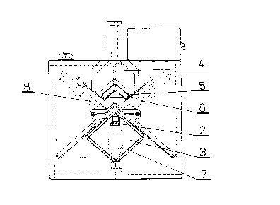
The subject of this invention is presented on drawings, where fig. 1 -
side view, fig. 2 - top view, fig. 3 - top view of a carrier in extreme positions of
the slider, fig. 4 - cross-section of a carrier in a slider front position.
The apparatus comprises the blocking device 2 of the ventilation duct
3 installed on the platen 1, a feeding device 4 of the angle plate 5, a fastening
device 6 to fasten the angle plate 5 in the ventilation duct 3 flange 7 and a
clamping device 8 to clamp the ventilation duct 3 flange 7 on angle plate 5
edges. The feeding device 4 of the angle plate 5 comprises a double arm
carrier 9 and a slider 10. There is a supply hopper 11 of angle plates 5 over
the carrier 9. The slider 10 slides along the guide bar 25 located in the lower
part of the base plate 19 and on the slider 10 working plane 14. The slider 10
is joined for good with the piston rod 15 of the cyiinder 16. The carrier 9 is
located on the base plate 19. The the slider 10 working plane 14 has a furrow
26. There is a port 23 and an oblong hole 21 on the base plate 19. In the front
part of the base plate 19 the fixed guide 24 is located over the furrow 26 in the
slider 10 working plane 14. Carrier 9 arms have oval holes 17 with stops 18
fixed for good to the base plate 1g. Ihere is a carrying pin 20 fixed to the
central part of the carrier 9. The carrying pin 20 is placed in an oblong hole 21
of the base plate and in an oblong slot 12 of the slider 10. The carrier 9 arms
end with clamps 22.
The operation of the apparatus according to the invention starts by
filling the supply hopper 11 with angle plates 5 and placing the ventilation duct
3 on the platen 1. When the apparatus is switched on, the blocking device 2
A,'~J,~

CA 02239312 1998-06-02
31~'
sets up the ventilation duct
E~D.~ ~r,,~ r

CA 02239312 1998-06-02
3 in a proper position and blocks it for the entire time of the placement cycle.When a ventilation duct is blocked, the feeding device 4 is activated. The
piston rod 15 of the cylinder 16 fixed for good to the slider 10 starts moving
backwards, in example away from the ventilation duct 3. When the front edge
of the slider 10 slot 1 2 reaches the carrying pin 20 fixed for good to the carrier
9, the slider 10 and the carrier 9 start moving backwards at the same moment.
The clamps 22 of carrier g arms catch the lowest angle plate 5 stacked in the
supply hopper 11 and move it towards the base plate 19 port 23. The angle
plate 5 drops down through the port 23 to the working plane 14 of the slider
10 until its corner reaches the slider 10 socket 13. The piston rod 15 of the
cylinder 16 changes its direction at the same time. The slider 10 moves the
angle plate 5 on the working plane 14 towards the ventilation duct 3. The
angle plate 5 is transported under the guide 24 which is installed in the lower
part of the base plate 19 over the furrow 26 on the slider 10 working plane 14.
The guide 24 presses the angle plate 5 corner causing its arms to rise. When
the back edge of the slider 10 slot 12 reaches the carrying pin 20 of the carrier
9, the carrier 9 and the slider 10 commence to move forward. The carrier 9
advances under the angle plate 5 supply hopper 11 and at the same time the
slider 10 places the angle plate 5 with the raised arms over the channel bar
flanges 7 of ventilation ducts 3. The fastening device 6 is switched on and
angle plate 5 arms are pressed into the channel bar flanges 7 of the
ventilation duct 3. The final stage of angle plate 5 placement is to activate two
clamping devices 8 which clamp the ventilation duct 3 flanges 7 on angle plate
5 edges.

Representative Drawing
A single figure which represents the drawing illustrating the invention.
Administrative Status

2024-08-01:As part of the Next Generation Patents (NGP) transition, the Canadian Patents Database (CPD) now contains a more detailed Event History, which replicates the Event Log of our new back-office solution.

Please note that "Inactive:" events refers to events no longer in use in our new back-office solution.

For a clearer understanding of the status of the application/patent presented on this page, the site Disclaimer , as well as the definitions for Patent , Event History , Maintenance Fee  and Payment History  should be consulted.

Event History

Description Date
Application Not Reinstated by Deadline 2001-03-29
Time Limit for Reversal Expired 2001-03-29
Deemed Abandoned - Failure to Respond to Maintenance Fee Notice 2000-03-29
Inactive: RFE acknowledged - Prior art enquiry 1998-12-07
Inactive: IPC assigned 1998-09-28
Classification Modified 1998-09-28
Inactive: First IPC assigned 1998-09-28
Request for Examination Requirements Determined Compliant 1998-09-02
All Requirements for Examination Determined Compliant 1998-09-02
Request for Examination Received 1998-09-02
Inactive: Notice - National entry - No RFE 1998-08-26
Application Received - PCT 1998-08-11
Application Published (Open to Public Inspection) 1997-07-17

Abandonment History

Abandonment Date Reason Reinstatement Date
2000-03-29

Maintenance Fee

The last payment was received on 1999-03-29

Note : If the full payment has not been received on or before the date indicated, a further fee may be required which may be one of the following

  • the reinstatement fee;
  • the late payment fee; or
  • additional fee to reverse deemed expiry.

Please refer to the CIPO Patent Fees web page to see all current fee amounts.

Fee History

Fee Type Anniversary Year Due Date Paid Date
MF (application, 2nd anniv.) - small 02 1998-03-30 1998-06-12
Basic national fee - small 1998-06-12
Request for examination - small 1998-09-02
MF (application, 3rd anniv.) - small 03 1999-03-29 1999-03-29
Owners on Record

Note: Records showing the ownership history in alphabetical order.

Current Owners on Record
WALTER KACZOROWSKI
Past Owners on Record
None
Past Owners that do not appear in the "Owners on Record" listing will appear in other documentation within the application.
Documents

To view selected files, please enter reCAPTCHA code :


To view images, click a link in the Document Description column. To download the documents, select one or more checkboxes in the first column and then click the "Download Selected in PDF format (Zip Archive)" or the "Download Selected as Single PDF" button.

List of published and non-published patent-specific documents on the CPD .

If you have any difficulty accessing content, you can call the Client Service Centre at 1-866-997-1936 or send them an e-mail at CIPO Client Service Centre.


Document
Description 
Date
(yyyy-mm-dd) 
Number of pages   Size of Image (KB) 
Description 1998-06-02 6 173
Abstract 1998-06-02 1 48
Drawings 1998-06-02 4 95
Claims 1998-06-02 3 80
Cover Page 1998-09-29 1 52
Representative drawing 1998-09-29 1 11
Notice of National Entry 1998-08-26 1 209
Acknowledgement of Request for Examination 1998-12-07 1 172
Courtesy - Abandonment Letter (Maintenance Fee) 2000-04-26 1 183
Fees 1999-03-29 1 36
PCT 1998-06-02 15 553