Note: Descriptions are shown in the official language in which they were submitted.
CA 02239841 1998-06-08
COMPLIANT HYDRODYNAMIC/HYDROSTATIC SHOE FOR PAPERMAKING PRESS
FIELD OF THE INVENTION
The present invention relates to an Extended Nip° press
apparatus for pressing water 'from a web of paper. More particularly,
s the present invention relates to a press apparatus having an elongate
shoe with a concave surface.
BACKGROUND OF THE INVENTION
Presses which employ a concave shoe engaged against a backing
roll, such as the Extended Nip° press manufactured by Beloit
Corporation of Beloit, Wisconsin, are used in a papermaking machine for
increasing the residence time of a web during passage of the web
through a pressing nip. Typically, a nip is defined as the narrow region
about the line of co-tangency when two rolls with aligned axes are
brought together. The nip between rolls has classically been used in
~s papermaking to remove water from the web, and to compress the fibers
in the web into a smooth surface. In the papermaking art, it has been
found to be desirable to increase the length of the nip, resulting in a
somewhat lower pressure and uniform pressing, and increased
effectiveness of pressing of the paper web. Initially, the length of the
1
CA 02239841 1998-06-08
nip was increased by coating one or both of the rolls with a compliant
material. The use of a compliant roll system allowed for nips somewhat
greater than an inch in length along the direction of the web through
the nip.
s The desire for even longer nips led to the development of the so-
called Extended Nip° press, or ENP. The ENP employs a backing roll
and an elongated shoe, where the elongated shoe has a concave
surface with a radius of curvature slightly larger than that of the convex
surface of the backing roll. The shoe, which is typically made of steel,
~o cooperates with the backing roll over a nip length of approximately ten
inches along the direction of travel of the paper web.
In this configuration, the shoe is stationary. Thus, without
further modification, a paper web moving through the nip formed
between the shoe and the backing roll would experience unacceptable
~s rubbing on the stationary shoe. To overcome this problem, a bearing
blanket forming a cylindrical tube is slidably disposed over the shoe and
around the support shaft on which the shoe is mounted. This bearing
blanket supports the paper web as it passes through the nip. To reduce
friction forces between the bearing blanket and the shoe, lubricant is
2o supplied between the bearing blanket and the shoe, allowing the bearing
blanket to slide freely across the shoe on a film of lubricant. A shoe of
this type is known as a hydrodynamic shoe.
The type of lubricant used affects the thickness of the film layer.
Higher viscosity lubricants create thicker film layers than do low
is viscosity lubricants; however, increased horsepower is needed to drive
the backing roll. In addition, as the rotational speed of the backing roll
decreases, the thickness of the film layer decreases. Thus, where the
backing roll is operating at low speed, it is difficult to maintain the film
layer.
2
CA 02239841 1998-06-08
To aid in drying or pressing of the paper web, a felt, or web
support blanket, often underlies and supports the paper web as it
transits the nip between the backing roll and the bearing blanket on the
shoe. The backing rolls, paper web, and web support blanket (if
s present) are frictionally engaged, and in turn engage the upper surface
of the bearing blanket, causing the bearing blanket to slide over the
shoe and rotate about the shoe and its support shaft.
A typical papermaking machine of which the Extended Nip~
Press forms a part can produce over one-half million square feet of
~o paper per hour of operation. Thus, it is desirable that the machine be in
operation as close to continuously as possible, with downtime for repair
or replacement of parts being kept to a bare minimum. One part that is
subject to replacement is the bearing blanket. As stated above, it is
subject to friction forces as it rotates about the shoe and the shoe
is support shaft. Due to the large pressure force in the nip, the bearing
blanket can also be damaged by paper wads or other deformation in the
paper web that cause the lubricant film layer between the shoe and
blanket to collapse. Blankets cost from about 5100,000 to 5200,000
each, so blanket damage from paper wads or other web deformities is a
2o serious problem in the papermaking industry. Further, it takes from four
to eight hours to replace a blanket, during which time no paper can be
made.
In an attempt to minimize such damage to the bearing blanket,
various shoe configurations have been proposed. One such
zs configuration is known as a hydrostatic shoe. In a hydrostatic shoe, the
concave portion of the shoe defines a pocket, so that at least for a
portion of the travel of the bearing blanket through the nip, the blanket
is hydrostatically supported with lubricant within the pocket. For
example, in U.S. Patent No. 5,262,011 to Ilmarinen ("the '011 patent"),
3o pockets are disclosed having several pocket zones where the trailing
3
CA 02239841 1998-06-08
edge of the pocket decreases to zero depth. Lubricant is supplied
directly to the pocket by channel means passing through the shoe.
One of the objectives of the '011 patent is to provide a shoe
configuration whereby damage to the bearing blanket from a paper wad
s entering the nip is reduced. However, if the hydrostatic pocket abruptly
terminates at the trailing end thereof, there is a tendency for a paper
wad to cause a sudden pressure surge as the wad moves between the
blanket and the concave surface at the trailing end of the pocket, thus
collapsing the lubricant film layer.
~o U.S. Patent No. 5,441,604 to Sand berg et al. ("the '604 patent")
also discloses a hydrostatic shoe, where the concave surface
encompasses a pocket. In the shoe of the '604 patent, lubricant is
supplied onto the concave surface upstream from the pocket and flows
into the pocket. The pocket acts to relieve pressure on the bearing
~s blanket caused by a paper wad entering the nip.
Both hydrodynamic shoes and hydrostatic shoes have rigid steel
concave surfaces.
As a result, tight tolerances are required to maintain a sufficient
lubricant film between the shoe and the bearing blanket. This is difficult
zo and expensive to accomplish, due to the large surface area of the shoe.
Moreover, hydrostatic shoes are expensive to manufacture, because the
pockets therein must be machined to exact dimensions.
Thus, there exists a need for an elongate shoe that is easier and
less expensive to manufacture, and that does not require tight
25 tolerances. There also exists a need for an elongate shoe which can
increase bearing blanket life, by significantly reducing damage to the
blanket from paper wads and web deformities passing through the nip.
4
CA 02239841 1998-06-08
SUMMARY OF THE INVENTION
The Extended Nip° press apparatus of this invention comprises a
rotatable backing roll and an elongate shoe that cooperates with the
backing roll for defining therebetween a nip of extended length for
s passage therethrough of a paper web. The shoe defines a concave
surface, where that surface has a layer of a compliant material thereon.
A bearing blanket is movably disposed between the backing roll and the
compliant material layer on the concave surface. The arrangement is
such that the paper web is supported by the bearing blanket, with the
~o web being disposed between the blanket and the backing roll.
Lubricant supply means are provided for supplying lubricant
between the compliant material layer on the concave surface and the
bearing blanket, such that the bearing blanket is slidingly supported by
the compliant material layer on the concave surface during passage of
~s the blanket through the nip.
The compliant material layer comprises an elastomer with a low
coefficient of friction and high abrasion resistance. It has the ability to
deform with increased pressure upon it, thus allowing a paper wad or
web deformity to pass through the nip without damage to the bearing
zo blanket.
It is a feature of the present invention to provide a concave shoe
for a press apparatus which is economical to manufacture.
It is another feature of the present invention to provide an
elongate press shoe which can increase bearing blanket life by reducing
is damage to the blanket from paper wads and web deformities passing
through a nip.
It is also a feature of the present invention to provide a shoe
which can contribute to reduced drive horsepower requirements, even
where high viscosity lubricants are used.
- CA 02239841 1998-06-08
Further objects, features and advantages of the invention will be
apparent from the following detailed description when taken in
conjunction with the accompanying drawings.
BRIEF DESCRIPTION OF THE DRAWINGS
s FIG. 1 is a side elevational view of an Extended Nip° press
apparatus of the present invention employing a hydrodynamic shoe.
FIG. 2 is a side elevational view of an alternative embodiment
Extended Nip° press apparatus of the present invention, employing a
hydrostatic shoe.
FIG. 3 is a side elevational view of an Extended Nip° press
apparatus of the present invention, illustrating means for attaching the
compliant layer to the shoe.
FIG. 4 is a graphical representation of the nip pressure profile
caused by a paper wad for various prior art shoe configurations, and the
~s shoe of the present invention having a concave surface with a layer of
compliant material thereon.
FIG. 5 is a graphical representation of horsepower versus
machine speed for prior art shoe configurations and the shoe of the
present invention having a concave surface with a layer of compliant
zo material thereon.
FIG. 6 is a graphical representation of lubricant film thickness
versus machine speed for prior art shoe configurations and the shoe of
the present invention having a concave surface with a layer of
compliant material thereon.
25 FIG. 7 is a graphical representation of the nip pressure profile for
prior art shoe configurations and the shoe of the present invention
having a concave surface with a layer of compliant material thereon.
FIG. 8 is an enlarged fragmentary cross-sectional view of the nip
of FIG. 3.
6
~ CA 02239841 1998-06-08
DESCRIPTION OF THE PREFERRED EMBODIMENTS
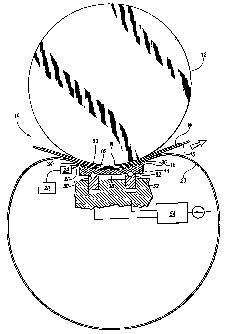
Referring more particularly to FIGS. 1-2, wherein like numbers
refer to similar parts, an Extended Nip° press apparatus 10 for
removing water from paper web W is shown in FIG. 1. The apparatus
s 10 includes a rotatable backing roll 12 and an elongate shoe_14, which
cooperates with the backing roll 12 for defining therebetween a nip N.
The shoe 14 defines a concave surface 16, which has a layer of
compliant material 18 thereon. The term "compliant material"
encompasses any material that is capable of being deformed or
~o compressed due to pressure forces exerted upon it of a magnitude
similar to those present in the nip N during operation of the apparatus
10. The nip N, which is typically about ten inches long, forces the paper
web W into extended and high pressure contact with the backing roll
12. The extended high pressure passage through the nip N is
~s advantageously used in presses, impulse dryers, and the like, to speed
the removal of water, or drying, of the paper web W in a papermaking
machine. Typically the web W will be supported on a felt or dryer
fabric 15 as it passes through the nip N.
A first support means 50 such as a hydraulically driven piston
2o cooperates with the elongate shoe 14 for urging the shoe 14 towards
the backing roll 12. A second support means 52 is disposed upstream
relative to the first support means 50. The second support means 52
cooperates with the elongate shoe 14 for urging the shoe 14 towards
the backing roll 12. A control means 54 is connected to both the first
Zs support means 50 and the second support means 52, for controlling the
disposition of the first support means 50 and the second support means
52 and hence the shoe 14. The arrangement is such that the
application of differential pressure in a machine direction is permitted.
In order to lower the friction between the paper web W and the
so shoe 14, a lubricated endless bearing blanket 20 is movably disposed,
7
CA 02239841 1998-06-08
as indicated by arrow 22, between the backing roll 12 and the layer of
compliant material 18 on the concave surface 16 of the shoe. The
arrangement is such that the paper web W is disposed between the
bearing blanket 20 and the backing roll 12. Means 24, are provided for
s supplying lubricant between the layer of compliant material 18 on the
concave surface 16 of the shoe 14 and the blanket 20, such that the
blanket is slidingly supported by the layer of compliant material 18
during passage of the blanket 20 through the nip N.
The means 24 for supplying lubricant is disposed upstream
~o relative to the shoe 14. The means 24 includes a plurality of nozzles 26
connected to a pressurized supply of lubricant 28, such that the
lubricant 30 is applied to the upstream end 32 of the shoe 14 between
the surface of the compliant material 18 and the blanket 20. The
lubricant 30 then moves downstream in the form of a lubricant film,
~s whose thickness varies, based on the pressure exerted upon it.
The layer of compliant material 18 comprises an elastomer having
a low coefficient of friction and high abrasion resistance. So that the
compliant material layer 18 can be deformed by pressure from the
lubricant film, the elastomer should be less rigid than the rigidity
Zo exhibited by the lubricant film as it passes over the compliant material
layer 18. Elastomers having a hardness of from about 30 to about 90,
measured by a shore A durometer are preferred. Suitable elastomers for
use in the compliant material layer include nitrite rubber,
fluoroelastomers, plastics and proprietary elastomers, such as 10+742
2s Slick Elastomer, available from John Crane Inc., Vandalia, Illinois.
These materials can also be reinforced with polyester fabric. In addition
to polyester fabric reinforcements, the materials may be reinforced with
nylon, cotton, Kevlar° , metal, carbon or any other fabric. Kevlar is a
trademark for a polymer material manufactured by E. I. du Pont de
8
CA 02239841 1998-06-08
Nemours and Company, Wilmington, Delaware. They may also be
coated with Teflon to obtain a lower coefficient of friction.
The compliant material layer 18 can be attached to the concave
rigid metal core 32 of the shoe 14 by various methods known in the art,
s such as bonding, coating or otherwise attaching the compliant material
to form the concave surface 16.
Preferably, as shown in FIGS. 3 and 8, the compliant material
layer 74 can be attached to the shoe 72 by clamping means 64 and 66,
which are located at upstream end 68 and downstream end 70
respectively of the shoe. The shoe is supported and moved toward and
away from the backing roll 12 by a piston 88. This configuration allows
for easy and rapid replacement of the compliant material layer 74. The
layer of compliant material 74 should be of a thickness to allow for it to
deform sufficiently from pressure generated by passage of a paper wad
~s or web deformity through the nip so that the bearing blanket is not
subjected to a sudden, deleterious pressure increase from the presence
of the paper wad or web deformity in the nip. Preferably, the thickness
of the compliant material layer should be uniform. A preferred thickness
for the compliant material layer is from about 0.1 to about 0.5 inches,
zo however, greater or lesser thicknesses may be employed.
As shown in FIG. 8, the compliant material layer 74 is connected
by fasteners to edge clamps 76. The edge clamps have parallel grooves
78 which receive protrusions 80 from an upstream bracket 82 and a
downstream bracket 84, such that the comparatively thin compliant
Zs layer material 74 can be clamped to the edge clamps 76 off-machine,
and the rigid edge clamps 76 then expeditiously inserted in the brackets
82, 84 and properly positioned and fixed in place by adjustment of a
plurality of set screws 86 or the like.
During operation of the press apparatus 10, pressure generated
3o by the lubricant film causes the layer of compliant material to compress
9
CA 02239841 1998-06-08
in thickness. Since the pressure from the lubricant film is less at the
upstream and downstream edges 34, 36 of the concave surface 16
than it is towards the center 38 of the concave surface 16, the
compliant material 18 will compress in thickness more at the center 38,
s than at the edges 34, 36, causing the formation of a shallow. pressure
"puddle," or pocket, in which the lubricant film is maintained. In
addition, the thickness of the lubricant film at the edges 34, 36 will be
less than that at the center 38, which acts to retard the escape of
lubricant from the shoe 14, and permits a continuous lubricant film to
be established. Since less lubricant escapes, the feed rate of lubricant
30 from the lubricant supply 28 can be less in the present invention
than is necessary in an Extended Nip° press apparatus of conventional
design.
As a paper wad or other web deformity enters the nip N, the
~s pressure caused by the wad or deformity causes the layer of compliant
material to compress in thickness, thereby substantially absorbing the
additional pressure generated by the paper wad or vveb deformity, and
allowing for its passage though the nip without damage to the bearing
blanket.
2o An alternative embodiment press apparatus 39 of the present
invention is shown in FIG. 2 employing a primarily hydrostatic type
shoe. The apparatus 39 has a shoe 58 disposed below a backing roll
59. The shoe 58 has one or more pockets 40 cut from the layer of
compliant material 56 attached to the metal shoe core 57. Lubricant 30
Zs is supplied to the pockets 40 via a lubricant supply channel 42.
Alternatively, lubricant 30 can be supplied to the pockets 40 as in the
apparatus 10 disclosed above and shown in FIG. 1, that is, through
nozzles disposed at the upstream end of the shoe 58. The lubricant 30
will then flow downstream in a film into the pockets 40. Such a shoe
3o should be less costly to manufacture than a hydrostatic shoe formed
CA 02239841 1998-06-08
entirely from metal, as it is easier to cut an elastomeric material to form
the pockets than it is to machine the pockets in an all-metal shoe.
The pockets 40 may be cut in any shape or dimension desired by
the user. Preferably, the pockets are concave in shape, and decrease
s gradually in depth toward the upstream and downstream ends 60 and
62 of the pocket 40, respectively, to a zero depth at ends 60 and 62.
However, other shapes, such as wedges or rectangles, can be used.
The pockets should be of sufficient depth for laminar flow to occur
therein.
The Extended Nip° press of the present invention has numerous
advantages over conventional Extended Nip presses. As stated above,
the compliant layer on the concave surface of the shoe protects the
blanket from damage due to a paper wad or other web deformity.
Further, the Extended Nip press of the present invention requires less
~s horsepower to operate the press roll, and allows lower viscosity
lubricants to be used, without sacrificing performance. These benefits
have been demonstrated in actual testing of the Extended Nip press of
the present invention, as is shown in the following examples.
EXAMPLE 1
so A paper wad was passed through (1 ) an Extended Nip press
apparatus having a steel hydrodynamic shoe, (2) an Extended Nip press
apparatus having a steel hydrostatic shoe, and (3) an Extending Nip
press apparatus of the present invention, where the concave surface of
the hydrodynamic shoe had a compliant layer thereon, comprising a
is rubber layer having a thickness of 0.25 inches. The nip load force was
set at 6,000 pounds per lineal inch ("pli") and the machine speed was
500 feet per minute ("fpm"y.
As illustrated in FIG. 4, a nip pressure profile was determined for
each of the presses discussed above. As can be seen in FIG. 4, the
11
CA 02239841 1998-06-08
Extended Nip press of the present invention (dotted line) had a lower
peak nip pressure level than either that exhibited by the Extended Nip
press with the hydrodynamic shoe (dashed line), or the Extended Nip
press with the hydrostatic shoe (solid line). Further, the nip pressure
s profile for the Extended Nip press of the present invention showed a
more gradual pressure gradient than did the profiles of the other two
presses.
Based on these results, a paper wad is much less likely to
damage the blanket where the Extended Nip press apparatus has a
compliant layer on the concave surface of the shoe, as compared to an
Extended Nip press apparatus having either a solid hydrodynamic shoe
or solid hydrostatic shoe.
EXAMPLE 2
FIG. 5 shows a plot of horsepower versus machine speed for (1 )
~s an Extended Nip press apparatus having a steel hydrodynamic shoe,
and no blanket (circle points), (2) an Extended Nip press apparatus
having a steel hydrodynamic shoe, with a blanket disposed between the
shoe and the press roll (square points), and (3) an Extended Nip press
apparatus of the present invention (triangle points), where the concave
zo surface of the hydrodynamic shoe has a compliant layer thereon,
comprising a rubber layer having a thickness of 0.25 inches, and a
blanket is disposed between the compliant layer and the press roll. As
shown in FIG. 5, for a given machine speed, the horsepower required to
operate the press roll is less for the Extended Nip press apparatus of the
25 present invention (dotted line), than that required to operate the press
roll for an Extended Nip press apparatus having a conventional
hydrodynamic shoe, with or without a blanket (dashed line and solid
line, respectively).
12
CA 02239841 1998-06-08
Thus, use of the Extended Nip press of the present invention will
require less energy than a conventional Extended Nip press apparatus.
EXAMPLE 3
FIG. 6 shows a plot of lubricant film thickness versus machine
s speed for the same three Extended Nip presses from Example 2, with
similar characters indicating data from the different presses. As can be
seen from the plot, for a given machine speed, at a nip load force of
6,000 pli, the Extended Nip press of the present invention maintains a
significantly thicker lubricant film layer (dotted line) than does a
~o conventional hydrodynamic shoe Extended Nip press with or without a
blanket (dashed tine and solid line, respectively).
Thus, the Extended Nip press of the present invention can
maintain a sufficient film layer to avoid blanket damage at lower
machine speeds than can a conventional Extended Nip press, and can
~s maintain a sufficient film layer at a given speed using a lower viscosity
lubricant than that required for a conventional Extended Nip press.
EXAMPLE 4
FIG. 7 shows nip pressure profiles generated for each of the three
Extended Nip presses from Example 2 during normal operation. As
2o shown in FIG. 7, the nip pressure profile of the Extended Nip press of
the present invention (dotted line) is similar to those of the conventional
hydrodynamic Extended Nip press, with or without a blanket (dashed
line and solid line, respectively).
Thus, the Extended Nip press of the present invention removes
is essentially the same amount of water from the web as does a
conventional hydrodynamic Extended Nip press.
It is understood that the invention is not limited to the particular
construction and arrangement of parts herein illustrated and described,
13
CA 02239841 1998-06-08
but embraces such modified forms thereof as come within the scope of
the following claims.
14