Language selection

Search

Patent 2240041 Summary

Third-party information liability

Some of the information on this Web page has been provided by external sources. The Government of Canada is not responsible for the accuracy, reliability or currency of the information supplied by external sources. Users wishing to rely upon this information should consult directly with the source of the information. Content provided by external sources is not subject to official languages, privacy and accessibility requirements.

Claims and Abstract availability

Any discrepancies in the text and image of the Claims and Abstract are due to differing posting times. Text of the Claims and Abstract are posted:

  • At the time the application is open to public inspection;
  • At the time of issue of the patent (grant).
(12) Patent: (11) CA 2240041
(54) English Title: TAMPER-EVIDENT LEAK-TIGHT CLOSURE FOR CONTAINERS
(54) French Title: FERMETURE INVIOLABLE ET ETANCHE POUR RECIPIENTS
Status: Expired and beyond the Period of Reversal
Bibliographic Data
(51) International Patent Classification (IPC):
  • B65D 41/48 (2006.01)
  • B65D 43/02 (2006.01)
(72) Inventors :
  • BARTSCH, ERIC RICHARD (United States of America)
(73) Owners :
  • BEVERAGES HOLDINGS, LLC
(71) Applicants :
  • BEVERAGES HOLDINGS, LLC (United States of America)
(74) Agent: DIMOCK STRATTON LLP
(74) Associate agent:
(45) Issued: 2004-08-17
(86) PCT Filing Date: 1996-12-12
(87) Open to Public Inspection: 1997-06-26
Examination requested: 1998-06-09
Availability of licence: N/A
Dedicated to the Public: N/A
(25) Language of filing: English

Patent Cooperation Treaty (PCT): Yes
(86) PCT Filing Number: PCT/US1996/019824
(87) International Publication Number: US1996019824
(85) National Entry: 1998-06-09

(30) Application Priority Data:
Application No. Country/Territory Date
08/572,950 (United States of America) 1995-12-15

Abstracts

English Abstract


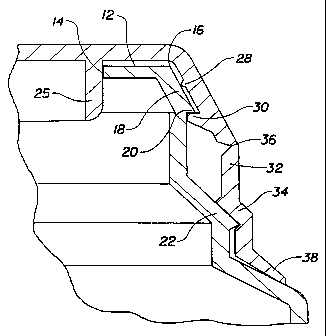
Disclosed is a closure for a container, such
as blow molded jug having a neck surrounding an
opening therein, the closure having a first annular
portion (26) and a second annular portion (32).
The first annular portion in the closure has a wiper
seal (28) and a lip seal (30). The second annular
portion exerts an upward pressure on the lip seal
which causes improved sealing and leak-tight
properties during shipping, handling, etc. The
upward pressure also enhances the effectiveness of
the wiper seal. The second annular portion may
include an annular tear skirt, defined by line of
weakness (36), having a pull tab for the removal
thereof to facilitate removal of the closure from the
container. The closure may also include a plug
seal, and a lower annular portion extending from
the second annular portion.


French Abstract

L'invention concerne une fermeture pour récipients de type flacon moulé par soufflage où l'ouverture est entourée d'un goulot. La fermeture a une première partie annulaire et une seconde partie annulaire. La première partie comporte un joint racleur et un joint à lèvres. La seconde partie exerce une pression vers le haut sur le joint à lèvres, ce qui améliore la fermeture et l'étanchéité pendant des opérations telles le transport et la manipulation, entre autre. Cette pression exercée vers le haut améliore en outre l'efficatité du joint racleur. La seconde partie peut comporter une bande d'arrachage annulaire dotée d'une patte à tirer en vue de faciliter l'enlèvement de la fermeture. Enfin, la fermeture peut comprendre un joint rentrant et une partie annulaire inférieure qui s'étend depuis la seconde partie annulaire.

Claims

Note: Claims are shown in the official language in which they were submitted.


6
What is claimed is:
1. A closure for a container, the container being of a type that has a neck
area, a top opening, an annular top surface with a periphery and an inner
edge, the
inner edge defining the top opening, a top outer rim extending from the
periphery of
the annular top surface, a lip formed at a lower edge of the top outer rim,
and a bottom
outer rim extending from the neck area;
the closure comprising a top member which covers the opening, the top
member having an inner surface and an outer surface, the closure further
comprising a
first annular portion extending from the top member, the first annular portion
further
comprising a lip seal which comes into sealing contact with the lip, the
closure further
comprising a second annular portion extending from the first annular portion,
the
second annular portion characterised by having a bottom foot which comes into
pressurized contact with the bottom outer rim such that a compressive force is
exerted
on the second annular portion, forcing the lip seal into sealable contact with
the lip.
2. A closure according to Claim 1, wherein the top outer rim defines a
first plane and the first annular portion defines a second plane, the first
plane being
substantially parallel to the second plane, the closure further comprising a
wiper seal
on the first annular portion which comes into sealing contact with the top
outer rim.
3. A closure according to Claim 1 or 2, further comprising a plug seal
extending from the inner surface of the top member, and coming substantially
into
contact with the inner edge of the annular top surface.
4. A closure according to Claim 3, wherein at least a portion of the top
member is recessed into the plug seal.
5. A closure according to any one of claims 1-4, further comprising at
least one line of weakness formed in the second annular portion at a position
between
the lip seal and the foot, and a pull tab having a first end and a second end,
the pull tab
being at least partially attached to the second annular portion at the first
end, whereby

7
the pull tab may be pulled outwardly to fracture the line of weakness and
remove a
substantial portion of the second annular portion from the closure to
facilitate removal
of the closure from the container.
6. A closure according to any one of claims 1-5, further comprising a
lower portion extending from the bottom foot, the lower portion allowing
improved
ease of removal of the closure from a manufacturing mold during manufacture of
the
closure.
7. A closure according to Claim 5, wherein the pull tab is frangibly
connected to a lower portion at the second end.

Description

Note: Descriptions are shown in the official language in which they were submitted.


CA 02240041 1998-06-09
WO 97/22526 PCT/US96/19824
1
TAMPER-EVIDENT LEAK-TIGHT CLOSURE FOR CONTAINERS
FIELD OF THE INVENTION
The present invention relates to tamper-evident, leak-tight closures for
containers, such as blow-molded plastic jugs, which are widely used in the
food and
beverage industry for the expendable packaging of consumables, such as cold
drinks
and the like. The present invention has further relation to such devices that
have a
frangible pull-tab for releasing and removing the closure from the container.
BACKGROUND OF THE INVENTION
Prior related closures of this genera! type may be seen, for example, in U.S.
Patent Nos. 3,893,583, 4,037,746, 4,066,182, 4,202,455, and 4,589,561. There
are
several problems with these prior art closures, however.
Maximum dimensional control of blow molded, plastic containers is achieved
at the outer surface of the container, which is formed in contact with the
mold. The
inner edges of the mouths of blow molded containers are trimmed, and because
the
trimming operation is not precise, the edges are not necessarily flat and free
of burrs
or other formations which would effect their dimensions. Consequently, Any
seal,
such as a plug seal, that attempts to seat a container at these inner edges is
subject to
the non-uniformity in dimension caused by the trimming operation. A much more
dependable seal may be achieved at, for example, the outer rim of the mouth of
a
container where the molded dimensions are more uniform.
Some prior art devices attempt to seal containers along a trimmed edge rather
than a molded outer surface. This makes the device prone to leakage. Some that
attempt to seal at the outer surface of containers do so inadequately, and are
known
to leak during shipping and storage of the containers. This offends consumers
and
makes the products undesirable and sometimes unsaleable. Some achieve adequate
sealability at the expense of aesthetic, cost, and ease-of use considerations.
Still
others are configured such that they are difficult to remove from molds during
their
manufacture.
There has therefore been a desire to have a tamper-evident closure for
containers, including improved sealability, which eliminates leakage during
shipping,
storage, and handling, while remaining aesthetically pleasing to consumers,
easy to
use, and inexpensive to produce. There is also a desire to provide such a
closure,
including a frangible pull-tab for easily releasing and removing the closure
from
containers, and which is relatively easy to remove from molds during
manufacture.

CA 02240041 1998-06-09
WO 97/22526 PCT/US96/19824
2
SUMMARY OF THE INVENTION
Disclosed is a closure for a container, the container being of a type that has
a
neck area, a top opening, an annular top surface with a periphery and an inner
edge
which defines the top opening, a top outer rim extending from the periphery of
the
annular top surface, the top outer rim defining a first plane, a lip formed at
the lower
edge of the top outer rim, and a bottom outer rim extending from the neck
area. The
closure has a top member which covers the opening, the top member has an inner
surface and an outer surface. The closure also has a first annular portion
extending
from the top member, the first annular portion defining a second plane, the
first plane
being substantially parallel to the second plane. The first annular portion
further
comprises a lip seal which comes into sealing contact with the lip. The first
annular
portion may also comprise a wiper seal which comes into contact with the top
outer
rim. The closure also has a second annular portion extending from the first
annular
portion. The second annular portion has a bottom foot which comes into
pressurized
contact with the bottom outer rim such that a compressive force is exerted on
the
second annular portion and the lip seal is forced into sealable contact with
the lip.
The closure may have at least one line of weakness formed in the second
annular portion at a position between the lip seal and the foot, and a pull
tab having a
first end and a second end, the pull tab being attached to the second annular
portion
at the first end, whereby the pull tab may be pulled outwardly to fracture the
line of
weakness and remove a substantial portion of the second annular portion from
the
closure to facilitate removal of the closure from the container. The pull tab
may be
frangibly connected to the second annular portion at the second end.
There may also be a lower portion extending from the bottom foot, the lower
portion allowing improved ease of removal of the closure from a manufacturing
mold
during manufacture of the closure. A plug seal extending from the inner
surface of
the top member, and coming substantially into contact with the inner edge of
the
annular top surface may be included. Also, a portion of the top member may be
recessed into the plug seal.
BRIEF DESCRIPTION OF THE DRAWINGS
While the specification concludes with claims particularly pointing out and
distinctly claiming the subject invention, it is believed the same will be
better
understood from the following description taken in conjunction with the
accompanying drawings in which:

CA 02240041 1998-06-09
WO 97/22526 PCT/LTS96/19824
3
Figure 1 is a vertical perspective view of a closure of the present invention,
showing the closure as applied to a container;
Figure 2 is a vertical sectional view through a closure of the present
invention, and a neck of a container on which the closure is applied;
Figure 3 is a vertical sectional view through a portion of the closure and a
portion of a neck of a container on which the closure is applied;
Figure 4 is a top plan view of the closure showing the pull-tab configuration;
Figure 5 is a side elevational view of the closure;
Figure 6 is a vertical sectional view of an alternative embodiment of the
closure of the present invention; and
Figure 7 is a chart showing the relationship between the compression in the
second annular portion of the closure and the pressures applied by both the
wiper and
lip seals of the present invention.
DETAILED DESCRIPTION OF THE INVENTION
Refernng now to the drawings in detail wherein Iike numerals indicate the
same element throughout the views, there is shown in Figures 1-5 an embodiment
of
a closure 10 of the present invention as applied to the top of a container.
Particularly
referring to Figures 2 and 3, the container typically has a neck area and an
opening.
The opening is encompassed by an annular top surface 12, which in turn has an
inner
edge 14 and a periphery 16. A top outer rim 18 angles downwardly and outwardly
from the periphery I6 of annular top surface 12. The outer surface of the top
outer
rim 18 serves as a "seat" for one of the seals of the closure. The lower edge
of the
top outer rim I8 overhangs a vertical portion of the neck area and forms lip
20. Lip
20 serves as a "seat" for another of the seats of the closure. Bottom outer
rim 22
extends downwardly and outwardly from the lower end of the vertical portion of
the
neck area and serves as a "seat" for a portion of the closure. This "seat"
exerts
compressive forces on the closure so as to maximize the effectiveness of the
seals and
provide for a leak-proof container; this will subsequently be described in
greater
detail.
The closure 10 has a top member 24 which acts as a cover for the opening in
the top of the container. The top member 24 may or may not have a plug seal 25
extending downward from its inside surface, such that the plug seal 25 is
substantially
forced into the opening along the inner edge 14, and provides for redundant
sealing
and stability of the closure 10. Extending at an angle from top member 24 is a
first
annular portion 26. On the inside surface of first annular portion 26 there
may be a

CA 02240041 1998-06-09
WO 97/22526 PCT/US96/19824
4
wiper seal 28 which comes into sealing contact with the outer surface of top
outer
rim 18. Wiper seal 28 may be positioned anywhere along the inner surface of
first
annular portion 26 while maintaining an adequate seal, but the most desirable
position for wiper seal 28 has been found to be at the low end of annular
portion 26
approaching lip 20. Lip seal 30 is also positioned on the inside surface of
annular
portion 26 such that it mates with and engages tip 20. The relationship among
wiper
seal 28, lip seal 30, and the compressive forces exerted on them, will be
described in
more detail below.
A second annular portion 32 extends downwardly from the first annular
portion 26. At the lower end of second annular portion 32 is a bottom foot 34
which
is configured to engage with bottom outer rim 22. The area of closure 10
between
lip seal 30 and bottom foot 34 is dimensioned with respect to the area of the
container between lip 20 and bottom outer rim 22 such that when closure 10 is
secured onto the container, a compressive force is exerted on closure 10
between
foot 34 and lip seal 30. This results in a seal between lip 20 and lip seal 30
of
maximum effectiveness.
When wiper seal 28 is included on first annular portion 26, the increase in
leak-proof sealability of closure 10 becomes dramatic. In addition to the
effectiveness of lip seal 30, wiper seal 28 is particularly effective due to a
bending
moment caused at the point of contact between lip 20 and lip seal 30, and
which ntns
around that same point. This moment is caused by the upwardly exerted
compressive
force within second annular portion 32. This compressive force causes first
annular
portion 26 to rotate inward around lip 20, and pushes wiper seal 28 into
secure
sealing contact with top outer rim 18. In the view shown in Figure 3, the
moment
would be counterclockwise around the point of contact between the lip 20 and
lip
seal 30.
Figure 7 shows curves depicting the general relationship between the
compressive force within second annular portion 32 (the °'X" axis) and
the pressure
on both the lip seal 30 and wiper seal 28 (the "Y" axis), for a specific
embodiment of
closure 10. These curves are exemplary, and do not predict this exact
relationship
for every possible embodiment of the present invention. The lower curve 35
shows
the increase in sealing pressure on lip seal 30 as the compressive force in
second
annular portion 32 increases. The pressure on lip seal 30 increases
substantially
steadily with the compressive force. However at some point the compressive
force
will become excessive and buckling will occur in second annular portion 32,
especially when second annular portion 32 includes line o~ weakness 36,
described
below. The upper curve 37 in Figure 7 shows that wiper seal 28 becomes

CA 02240041 1998-06-09
WO 97/22526 PCT/US96119824
particularly effective with increased compression of second annular portion
32, and
provides for about double the sealing force per unit area over that of lip
seal 30 for a
given amount of compression within second annular portion 32. This is due to
the
aforementioned moment, which rotates about the point of contact between lip 20
and
lip seal 30, and pushes wiper seal 28 into top outer rim 18.
Referring to Figures 2 and 3, a lower portion 38 may extend downwardly
and outwardly from bottom foot 34. Lower portion 38 is not necessary to the
proper
functioning of closure 10, and serves more of an aesthetic purpose. It has,
however,
been found to be useful in increasing the ease of removal of the closure from
the
molds during manufacture.
Within second annular portion 32, there may be positioned at least one line
of weakness 36 which is purposely fractured when removal of closure 10 from
the
container is desired, to release compressive forces in second annular portion
32 and
to facilitate removal of closure 10 from the container. A pull tab 40, shown
in Figure
4, may be attached to either lower portion 38, or second annular portion 32,
or both,
such that when the tab 40 is pulled, line of weakness 36 fractures, and most
or all of
second annular portion 32, and all of lower portion 38, may be completely
removed
to provide for opening of the container. The outer end of pull tab 40 may be
connected to lower portion 38 by a small frangible piece of material 42, to
prevent
tab 40 from being moved and causing inadvertent fracture of line of weakness
36
during shipping, handling, etc. This type of closure removal system is well
known in
the art.
As shown in Figure 6, a portion 44 of top member 24 may be recessed into
plug seal 25 to provide for a depression on the top surface of closure 10.
However,
this is usually undesirable because of the tendency for such a depression to
collect
dirt, dust, and other undesirable matter that would offend the consumer.
While particular embodiments of the present invention have been illustrated
and described herein it will be obvious to those skilled in the art that
various changes
and modifications can be made without departing from the spirit and scope of
the
present invention and it is intended to cover in the appended claims all such
modifications that are within the scope of this invention.

Representative Drawing
A single figure which represents the drawing illustrating the invention.
Administrative Status

2024-08-01:As part of the Next Generation Patents (NGP) transition, the Canadian Patents Database (CPD) now contains a more detailed Event History, which replicates the Event Log of our new back-office solution.

Please note that "Inactive:" events refers to events no longer in use in our new back-office solution.

For a clearer understanding of the status of the application/patent presented on this page, the site Disclaimer , as well as the definitions for Patent , Event History , Maintenance Fee  and Payment History  should be consulted.

Event History

Description Date
Time Limit for Reversal Expired 2009-12-14
Letter Sent 2008-12-12
Inactive: IPC from MCD 2006-03-12
Letter Sent 2005-07-25
Revocation of Agent Requirements Determined Compliant 2004-10-21
Inactive: Office letter 2004-10-21
Appointment of Agent Requirements Determined Compliant 2004-10-21
Revocation of Agent Request 2004-09-22
Appointment of Agent Request 2004-09-22
Grant by Issuance 2004-08-17
Inactive: Cover page published 2004-08-16
Inactive: Final fee received 2004-06-03
Pre-grant 2004-06-03
Letter Sent 2003-12-17
Notice of Allowance is Issued 2003-12-17
Inactive: Approved for allowance (AFA) 2003-12-05
Amendment Received - Voluntary Amendment 2003-10-20
Inactive: S.30(2) Rules - Examiner requisition 2003-07-11
Amendment Received - Voluntary Amendment 2003-05-29
Inactive: S.30(2) Rules - Examiner requisition 2002-12-02
Inactive: First IPC assigned 1998-10-06
Classification Modified 1998-10-06
Inactive: IPC assigned 1998-10-06
Inactive: Acknowledgment of national entry - RFE 1998-08-21
Application Received - PCT 1998-08-18
All Requirements for Examination Determined Compliant 1998-06-09
Request for Examination Requirements Determined Compliant 1998-06-09
Application Published (Open to Public Inspection) 1997-06-26

Abandonment History

There is no abandonment history.

Maintenance Fee

The last payment was received on 2003-11-20

Note : If the full payment has not been received on or before the date indicated, a further fee may be required which may be one of the following

  • the reinstatement fee;
  • the late payment fee; or
  • additional fee to reverse deemed expiry.

Patent fees are adjusted on the 1st of January every year. The amounts above are the current amounts if received by December 31 of the current year.
Please refer to the CIPO Patent Fees web page to see all current fee amounts.

Owners on Record

Note: Records showing the ownership history in alphabetical order.

Current Owners on Record
BEVERAGES HOLDINGS, LLC
Past Owners on Record
ERIC RICHARD BARTSCH
Past Owners that do not appear in the "Owners on Record" listing will appear in other documentation within the application.
Documents

To view selected files, please enter reCAPTCHA code :


To view images, click a link in the Document Description column (Temporarily unavailable). To download the documents, select one or more checkboxes in the first column and then click the "Download Selected in PDF format (Zip Archive)" or the "Download Selected as Single PDF" button.

List of published and non-published patent-specific documents on the CPD .

If you have any difficulty accessing content, you can call the Client Service Centre at 1-866-997-1936 or send them an e-mail at CIPO Client Service Centre.

({010=All Documents, 020=As Filed, 030=As Open to Public Inspection, 040=At Issuance, 050=Examination, 060=Incoming Correspondence, 070=Miscellaneous, 080=Outgoing Correspondence, 090=Payment})


Document
Description 
Date
(yyyy-mm-dd) 
Number of pages   Size of Image (KB) 
Representative drawing 1998-10-07 1 7
Claims 2003-05-28 2 80
Description 1998-06-08 5 294
Claims 1998-06-08 2 62
Drawings 1998-06-08 3 56
Abstract 1998-06-08 1 59
Claims 2003-10-19 2 65
Representative drawing 2004-07-12 1 9
Notice of National Entry 1998-08-20 1 235
Courtesy - Certificate of registration (related document(s)) 1998-08-20 1 140
Commissioner's Notice - Application Found Allowable 2003-12-16 1 160
Maintenance Fee Notice 2009-01-25 1 171
PCT 1998-06-08 8 233
Correspondence 2004-06-02 1 49
Correspondence 2004-09-21 19 735
Correspondence 2004-10-20 1 15
Correspondence 2004-10-20 1 18
Fees 2004-12-08 1 30