Language selection

Search

Patent 2240052 Summary

Third-party information liability

Some of the information on this Web page has been provided by external sources. The Government of Canada is not responsible for the accuracy, reliability or currency of the information supplied by external sources. Users wishing to rely upon this information should consult directly with the source of the information. Content provided by external sources is not subject to official languages, privacy and accessibility requirements.

Claims and Abstract availability

Any discrepancies in the text and image of the Claims and Abstract are due to differing posting times. Text of the Claims and Abstract are posted:

  • At the time the application is open to public inspection;
  • At the time of issue of the patent (grant).
(12) Patent: (11) CA 2240052
(54) English Title: LASER BEAM MACHINING DEVICE
(54) French Title: DISPOSITIF D'USINAGE A FAISCEAU LASER
Status: Deemed expired
Bibliographic Data
(51) International Patent Classification (IPC):
  • B23K 26/00 (2006.01)
  • A61F 9/06 (2006.01)
  • B23K 26/02 (2006.01)
  • B23K 26/42 (2006.01)
(72) Inventors :
  • HOSODA, NAOYOSHI (Japan)
(73) Owners :
  • NIHON WELDING CO., LTD. (Japan)
  • HOSODA, NAOYOSHI (Japan)
(71) Applicants :
  • NIHON WELDING CO., LTD. (Japan)
  • HOSODA, NAOYOSHI (Japan)
(74) Agent: RIDOUT & MAYBEE LLP
(74) Associate agent:
(45) Issued: 2002-01-15
(22) Filed Date: 1998-06-09
(41) Open to Public Inspection: 1999-08-10
Examination requested: 1998-10-07
Availability of licence: N/A
(25) Language of filing: English

Patent Cooperation Treaty (PCT): No

(30) Application Priority Data:
Application No. Country/Territory Date
10-28335 Japan 1998-02-10

Abstracts

English Abstract


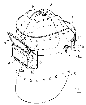
A protective mask which has a face shield and an eye
shield is used for safety when a worker machines a workpiece
by a laser beam. Start switches are provided in the mask,
and closed when a worker wears the mask. A laser torch,
a conductive clip and a laser oscillator are connected in
series. When a workpiece is brought in contact with the
end of a taper nozzle of the laser torch and the conducting
clip, an electric current is sent from a power source to
the laser oscillator, which is oscillated. Thus, accident
by laser beam owing to unexpected electric conduction is
prevented.


Claims

Note: Claims are shown in the official language in which they were submitted.


CLAIMS:

1. A laser beam machining device, comprising:
a laser oscillator for generating a laser beam;
optical fibers connected to said laser oscillator to guide the laser beam;
a laser torch which comprises a pipe which has a taper nozzle at a front end,
a
going-out end of said optical fibers being provided in the pipe so that the
laser beam
from the going-out end is focused in the vicinity of an end of the taper
nozzle;
a conducting clip configured to clip a workpiece to enable passage of an
electric
current through the workpiece;
a protective mask which a worker wears which further comprises a face shield
and
an eye shield, the mask incorporating at least three switches, the switches
comprising:
a prior switch which is connected to said laser oscillator, said prior switch
located so as to be actuated when the protective mask is placed on the
worker's head and being closed when the worker wears said protective
mask and face shield;
a first start switch located so as to be actuated when the face shield is
moved
to a location protecting the face of the worker; and
a second start switch actuated when the eye shield is moved to a closed
position;
operation of the laser oscillator being enabled when the prior switch and the
first and
second start switches are actuated so that the face mask is being worn and


the face shield is down over the worker's face and the eye shield is closed
and
when the end of the taper nozzle and said conducting clip are brought into
contact with the workpiece to initiate an enabled state allowing the passage
of electric current to said laser oscillator from a power source to oscillate
said
laser oscillator.
2. The laser beam machining device as claimed in claim 1 wherein a condenser
lens is provided in the pipe in front of the going-out end of the optical
fibers so that
the laser beam from the going-out end may be focused in the vicinity of the
end of
the taper nozzle.
3. The laser beam machining device as claimed in claim 1 wherein the start
switch is opened by pivoting the face shield upwards and closed by the face
shield
downwards to cover a face of the worker.
4. The laser beam machining device as claimed in claim 1 wherein the prior
switch, the first start switch and the second start switch are connected in
series.
5. The laser beam machining device as claimed in claim 1 further comprising a
trigger-type switch connected so that the laser oscillator is enabled only
when the
trigger-type switch is also actuated, which trigger-type switch is mounted on
a handle
of the laser torch.
6. The laser beam machining device as claimed in claim 1 wherein a radio
transmitter is provided in a circuit for connecting the switches of the
protective mask,
and a radio receiver for receiving an electric wave from the radio transmitter
is
provided in a circuit for connecting the conducting means and the laser
oscillator.
7. The laser beam machining device as claimed in claim 1 further comprising a


radio transmitter provided in the circuit for the laser control power source
connected
to the first and second start switches of the protective mask; and a radio
receiver for
receiving an electric wave from the radio transmitter provided configured such
that
a condition where both the first and second start switches are closed will be
indicated
without need for a wiring connection to the protective mask.
8. The laser beam machining device as claimed in claim 7, wherein the pipe,
trigger-type switch and connecting clip are connected in series with the laser
control
power source when the pipe is electrically connected with the conducting clip
via the
workpiece, and the circuit for the laser control power source further
comprises a
switch opened and closed in response to the electric wave received by the
receiver
and connected in series with said pipe trigger-type switch, connecting clip
and laser
control power source.
9. The laser beam machining device as claimed in claim 1, further comprising a
circuit for the laser control power source including the prior switch, the
first and
second start switches, the conducting clip, and the pipe included in the laser
torch,
all connected in series with the laser control power source and the circuit
being
completed when the pipe is electrically connected to the conducting clip via
the
workpiece, the prior switch is closed, and the first and second start switches
are
closed, thereby enabling electric current to be forwarded to the laser
oscillator from
the laser control power source.
10. The laser beam machining device of claim 9, further comprising a control
line
connecting the pipe and the laser control power source and a flexible tube,
the
control line being inserted with the optical fibers in the flexible tube.


11. A laser beam machining device, comprising:
a laser oscillator for generating a laser beam;
optical fibers connected to said laser oscillator to guide the laser beam;
a laser control power source;
a laser torch which comprises a pipe which has a taper nozzle at a front end,
a going-
out end of said optical fibers being provided in the pipe so that the laser
beam
from the going-out end is focused in the vicinity of an end of the taper
nozzle
and a handle, said pipe being electrically connected to the laser control
power
source;
a conducting clip which can clip a workpiece to pass an electric current to
the
workpiece;
a protective mask which a worker wears which has a face shield and an eye
shield;
a first start switch which is opened by pivoting the face shield upwards and
closed by
pivoting the face shield downwards to cover a face of the worker; and
a second start switch which is provided near the eye shield in the face
shield, said
second start switch being opened by pivoting the eye shield upwards and
closed by pivoting the eye shield downwards, said first and second start
switches being closed when the worker wears said face shield, when the eye
shield is closed;
a trigger-type prior switch incorporated in the handle of the laser torch;
a circuit for the laser control power source comprising the pipe of the laser
torch, the
conducting clip, the trigger-type prior switch, and the first and second start
switches;


the circuit for the laser control power source being configured so that when
the end
of the taper nozzle and said conducting clip are brought into contact with the
workpiece, and the trigger-type prior switch and the first and second start
switches are closed they laser control power source allows passage of electric
current to said laser oscillator to oscillate said laser oscillator.
12. The laser beam machining device as claimed in claim 11 wherein a condenser
lens is provided in the pipe in front of the going-out end of the optical
fibers so that
the laser beam from the going-out end may be focused in the vicinity of the
end of
the taper nozzle.
13. The laser beam machining device as claimed in claim 11 wherein the circuit
for the laser control power source is connected in series with the laser
control power
source and the circuit is completed when the pipe is electrically connected to
the
conducting clip via the workpiece, the trigger-type prior switch is closed,
and the first
and second start switches are closed thereby enabling electric current to be
forwarded to the laser oscillator from the laser control power source.

Description

Note: Descriptions are shown in the official language in which they were submitted.


CA 02240052 1998-06-09
SPECIFICATION
LASER BEAM MACHINING DEVICE
BACKGROUND OF THE INVENTION
The present invention relates to a laser beam
machining device in which a laser beam is guided by optical
fibers to machine a workpiece.
In a laser beam machining device where a laser beam
generated by a laser oscillator is introduced to a workroom
via optical fibers to conduct machining such as cutting
and welding, it is necessary to focus the laser beam exactly
at any time to a workpiece.
The laser beam provides large energy and needs much
care to safety. Thus, a laser torch is generally moved
by an automatic device, keeping a distance to the workpiece
to be machined. Further, if the laser beam is emitted from
a laser torch only when a worker wears a protective mask
exactly, safety will be increased.
In order to move the laser torch while a predetermined
distance to the workpiece is kept by the automatic device,
the device becomes larger and complicate, and is expensive.
Further, it is difficult to handle, and has very low
efficiency to machine a small amount of workpieces.
BRIEF DESCRIPTION OF THE DRAWINGS
The features and advantages of the invention will
become more apparent from the following description with
respect to embodiments as shown in appended drawings
- 1 -


CA 02240052 1998-06-09
wherein:
Fig. 1 is a perspective view of a protective mask in
a laser beam machining device according to the present
invention;
Fig. 2 is a perspective view which shows the first
embodiment of a laser beam machining device according to
the present invention;
Fig. 3 is a circuit diagram of the first embodiment
in Fig. 2;
Fig. 4 is a circuit diagram of the second embodiment
of the present invention; and
Fig. 5 is a circuit diagram of the third embodiment
of the present invention.
SUMMARY OF THE INVENTION
An object of the present invention is to provide a
laser beam machining device which machines a workpiece
safely and easily. According to the present
invention, there is provided a laser beam machining device,
comprising:
a laser oscillator for generating a laser beam;
optical fibers connected to said laser oscillator to
guide the laser beam;
a laser torch which comprises a pipe which has a taper
nozzle at a front end, a going-out end of said optical
f fibers being provided in the pipe so that the laser beam
from the going-out end is focused in the vicinity of an
- 2 -


CA 02240052 1998-06-09
end of the taper nozzle;
conducting means for passing an electric current to
a workpiece;
a protective mask which has a face shield which a
worker wears; and
a start switch which is connected to said laser
oscillator, said start switch being closed when the worker
wears said face shield and when the end of the taper nozzle
and said conducting means are brought into contact with
the workpiece, to pass the electric current to said laser
oscillator from a power source to oscillate said laser
oscillator.
When the worker wears the protective mask exactly and
when the end of the laser torch is brought into contact
with the workpiece, the laser beam is automatically
generated, thereby facilitating operation and assuring
safety without emitting the laser beam unexpectedly.
DETAILED DESCRIPTION OF PREFERRED EMBODIMENTS
Fig. 1 is one embodiment of a welding protective mask
1 according to the present invention.
The protective mask 1 comprises an engagement ring
2 which can be engaged over a head of a worker; a suspension
band 3 which is integrally connected with the engagement
ring 2; and a face shield 5 which is pivoted about pivots
4 to the engagement ring 2 to cover the upper surface of
the head of the worker.
- 3 -


CA 02240052 1998-06-09
On the front surface of the face shield 5, an eye
window frame 6 is provided, and the upper edge of an opening
eye shield 7 is pivoted above the eye window frame 6 about
pivots 8. A tension spring 9 is mounted between the side
of the eye shield 7 and the front surface of the face shield
5 slightly lower than the pivot 8. If the eye shield 7
is fully opened or closed, such a fully opened or closed
condition of the eye shield 7 is elastically maintained
by stretching the tension spring 9.
On the lower surface of the middle of the suspension
band 3, a push-button prior switch 10 is mounted. When
the worker wears the suspension band 3, the prior switch
10 is pressed and closed by the top of his head. Behind
one of the pivots 4, a first start switch 11 which contains
an inclined piece 11a is mounted. When the face shield
5 is turned upwards about the pivot 4, the inclined piece
11a of the first start switch 11 is pressed by the side
end 5a of the face shield 5, and the first start switch
11 is opened. When the face shield 5 is turned downwards
to cover a face of the worker, the inclined piece 1Ia is
projected without being pressed and contacts of the first
start switch llis closed.
On the inside of the side wall of the eye window frame
6, a second start switch 12 which comprises a microswitch
is mounted. When the eye shield 7 is opened upwards, it
gets away from an operative projection 12a of the second
- 4 -


CA 02240052 1998-06-09
start switch 12 and the second start switch 12 is opened.
When the eye shield 7 is closed, the operative projection
12a is pressed and the second start switch 12 is closed.
The prior switch 10, the first start switch 11 and
the second start switch 12 are connected in series and
closed to prepare welding. The details thereof follow
Fig. 2 is a perspective view which illustrates the
first embodiment of a laser beam machining device according
to the present invention which contains the foregoing
protective mask 1, and Fig. 3 is a circuit diagram of the
first embodiment.
The numeral 13 in Figs . 2 and 3 denotes a laser torch
in which a taper nozzle 16 is provided in the front portion
of a pipe 15 in which a suitable condenser lens 14 is
provided, a handle 17 extending perpendicular to an axis
of the pipe 15. In the pipe 15, a flexible tube 18 is
inserted from the rear end. In the flexible tube 18,
optical fibers 20 from a laser oscillator 19 and a control
line 22 from a laser control power source 21 are inserted.
A going-out end 20a for the optical fibers 20 is positioned
right behind the condenser lenses 14 in the pipe 15. The
end 22a of the control line 22 is connected to the pipe
15.
At the end of a lead 23 from an output contacting point
10a of the prior switch 10 of the protective mask 1, a
conducting clip 25 which can hold a metal workpiece 24 is
- 5 -


CA 02240052 1998-06-09
secured.
The prior switch 10, the first start switch 11 and
the second start switch 12 are connected with a lead in
series, and an input contacting point 12a of the second
start switch 12 is connected to the laser control power
source 21 via a lead 27.
The operation thereof will be described as below.
After the workpiece 24 is clipped by the conducting
clip 25, the worker puts on the protective mask 1 and the
prior switch 10 is closed by the top of his head. Then,
the face shield 5 and the eye shield 7 are turned downwards,
so that the switches 10, 11 and 12 are closed and connected
to the laser control power source via a lead 27. The end
of the tapered nozzle 16 0~ the pipe 16 of the laser torch
13 is brought into contact with a welding portion of the
workpiece 24. A circuit for the laser control power source
21 is made, and an electric current is forwarded to the
laser oscillator 19, which is thus actuated to generate
a laser beam.
The laser beam is emitted from the end 20a of the
optical fibers 20, and focused at a portion to be welded
on the workpiece 24. The laser torch 13 is moved on the
workpiece 24, thereby assuring easy safety welding.
Without mounting the prior switch 10 for making a
circuit for the laser control power source on the
suspension band 3 of the protective mask 1, the prior switch
- 6 -


CA 02240052 1998-06-09
may be mounted to the handle 17 of the laser torch 13
or at a position which is far from the protective mask 1.
In the second embodiment as shown in Fig. 4, the
protective mask 1 has no prior switch in the middle of the
5 lower surface of the suspension band 3 as shown in Figs.2
and 3, but a trigger-type prior switch 28 is mounted to
a handle 17 of the laser torch 13. In Fig. 4, the same
numerals are allotted to the same members in Figs. 2 and
3, and description thereof is omitted. The conducting
10 clip 25 and the first start switch 11 are connected via
the trigger-type prior switch 28 on the handle 17. The
others are similar to those in Figs. 2 and 3. Compared
with the prior switch 10 mounted to the suspension band
3 of the protective mask 1, the trigger- type prior switch
28 can be surely operated, and if operation does not begin,
the laser oscillator 19 is not operated, thereby increasing
safety.
In the foregoing embodiments, the first start switch
11 operated by closing the face shield 5 and the second
start switch 12 operated by closing the eye shield 7 are
connected in series to generate a laser beam, but only a
single start switch may be provided.
The switches 10, 11 and 12 in the protective mask 1
may be connected to the laser control power source 21
wirelessly without the lead 27 in the third embodiment as
shown in Fig. 5. There are a radio transmitter 29 in the
7 _


CA 02240052 1998-06-09
lead 26 for connecting the switches 10, 11 and 12 of the
protective mask 1, and a radio receiver 30 for receiving
an electric wave from the radio transmitter 29 in the lead
23 for connecting the conducting clip 25 to the laser
control source 21. The others are the same as those in
Fig. 3. Thus, working efficiency is increased without
wiring.
The foregoing merely relate to embodiments of the
invention. Various modifications and changes may be made
by persons skilled in the art without departing from the
scope of claims wherein:
_ g _

Representative Drawing
A single figure which represents the drawing illustrating the invention.
Administrative Status

For a clearer understanding of the status of the application/patent presented on this page, the site Disclaimer , as well as the definitions for Patent , Administrative Status , Maintenance Fee  and Payment History  should be consulted.

Administrative Status

Title Date
Forecasted Issue Date 2002-01-15
(22) Filed 1998-06-09
Examination Requested 1998-10-07
(41) Open to Public Inspection 1999-08-10
(45) Issued 2002-01-15
Deemed Expired 2012-06-11

Abandonment History

There is no abandonment history.

Payment History

Fee Type Anniversary Year Due Date Amount Paid Paid Date
Application Fee $150.00 1998-06-09
Registration of a document - section 124 $100.00 1998-09-25
Request for Examination $200.00 1998-10-07
Maintenance Fee - Application - New Act 2 2000-06-09 $50.00 2000-05-16
Maintenance Fee - Application - New Act 3 2001-06-11 $50.00 2001-06-08
Final Fee $150.00 2001-10-11
Maintenance Fee - Patent - New Act 4 2002-06-10 $50.00 2002-04-15
Maintenance Fee - Patent - New Act 5 2003-06-09 $75.00 2003-04-16
Maintenance Fee - Patent - New Act 6 2004-06-09 $100.00 2004-04-16
Maintenance Fee - Patent - New Act 7 2005-06-09 $100.00 2005-04-12
Maintenance Fee - Patent - New Act 8 2006-06-09 $100.00 2006-04-13
Maintenance Fee - Patent - New Act 9 2007-06-11 $100.00 2007-04-19
Maintenance Fee - Patent - New Act 10 2008-06-09 $125.00 2008-06-02
Maintenance Fee - Patent - New Act 11 2009-06-09 $125.00 2009-03-04
Maintenance Fee - Patent - New Act 12 2010-06-09 $125.00 2010-04-13
Owners on Record

Note: Records showing the ownership history in alphabetical order.

Current Owners on Record
NIHON WELDING CO., LTD.
HOSODA, NAOYOSHI
Past Owners on Record
None
Past Owners that do not appear in the "Owners on Record" listing will appear in other documentation within the application.
Documents

To view selected files, please enter reCAPTCHA code :


To view images, click a link in the Document Description column. To download the documents, select one or more checkboxes in the first column and then click the "Download Selected in PDF format (Zip Archive)" or the "Download Selected as Single PDF" button.

List of published and non-published patent-specific documents on the CPD .

If you have any difficulty accessing content, you can call the Client Service Centre at 1-866-997-1936 or send them an e-mail at CIPO Client Service Centre.


Document
Description 
Date
(yyyy-mm-dd) 
Number of pages   Size of Image (KB) 
Abstract 1998-06-09 1 17
Description 1998-06-09 8 248
Claims 1998-06-09 3 72
Drawings 1998-06-09 5 91
Claims 2001-07-24 5 178
Cover Page 2001-12-18 1 39
Cover Page 1999-08-11 1 33
Representative Drawing 2001-12-18 1 12
Representative Drawing 1999-08-11 1 9
Fees 2001-06-08 1 32
Correspondence 2002-04-16 1 12
Correspondence 2002-01-24 1 34
Fees 2003-04-16 1 31
Prosecution-Amendment 1999-04-14 77 4,849
Fees 2005-04-12 1 26
Correspondence 2001-10-11 1 41
Prosecution-Amendment 2001-07-24 7 261
Prosecution-Amendment 2001-01-30 2 96
Fees 2002-04-15 2 46
Assignment 1998-09-25 2 63
Prosecution-Amendment 1998-10-07 1 26
Assignment 1998-06-09 2 91
Correspondence 1998-08-25 1 30
Correspondence 2002-04-12 2 52
Fees 2000-05-16 1 24
Fees 2004-04-16 1 37
Fees 2006-04-13 1 29
Fees 2007-04-19 1 28
Fees 2008-06-02 2 52
Correspondence 2008-06-02 2 52
Fees 2009-03-04 1 35
Fees 2010-04-13 1 34