Note: Descriptions are shown in the official language in which they were submitted.
v , WO 97/22793 CA 0 2 2 4 017 9 19 9 8 - 0 6 - 12 - p~~s96/20003
1 T
FUEL CONSUMPTION OPTIMIZER AND CARBON DIOXIDE EMISSIONS
REDUCER BASED ON AN AIR-VACUUM LIQUID COMPENSATION SYSTEM
FIELD OF THE INVENTION
The present invention concerns internal combustion engines, and more
particularly,
this invention refers specifically to the optimal reduction of fuel
consufnption
derived from the increase of volumetric and combustion efficiencies, produced
by
additional air supplied through the intake manifold, while reducing the work
and
vacuum effort of pistons. All of which allows a simultaneous reduction of fuel
and
a noticeable power boost. The system is intended to work for most internal
combustion engines.
BACKGROUND OF THE INVENTION
9. DEFINITION OF TERMS.
A) Internal combustion engines: in general refers to engines that naturally
aspirate with a throttle valve controlling and restricting the air flow
through the
intake manifold and where fuel does not partake in a lubricant function.
B) Any fuel delivery system, for example, carburetor, throttle body injection
continuous injection system, multipoint injection, pulsed electronic fuel
injection,
mixer dosifier of air for natural gas or liquid petroleum gas, diesel direct
injection.
C1 Any fuel: refers mainly to fuels inflammable by a spark of ignition, such
as:
gasoline, methanol, ethanol, or gasohol mixtures, natural gas, liquid
petroleum gas.
In case of any reference to diesel or fuel-oil, we will refer specifically to
them.
2. BACKGROUND DISCUSSION
It is common knwvledge that for a conventional combustion engine, the ideal
combustion could be defined by the relation between: the maximum amount of
energy generated by the minimum amount of fuel mixed with the exact amount of
oxygen present i a the air-fuel mixture, uniformly distributed in each
cylinder to
produce the total burning of fuel, white a minimum production of solid
residues and
polluting emission results. This definition would represent reaching almost
100%
CA 02240179 1998-06-12
, WO 97/22793 PCT/ilS96i10003
r t
-2-
efficiency in a combustion process. For the purpose of reaching maximum
efficiency and a significant reduction of fuel consumed by internal combustion
engines, it is convenient to discriminate the main factors involved in the
combustion process as well as the problems and limitations of operational
design
inherent to engines and how it affects their internal combustion and
performance.
3. OXYGEN, ESSENTIAL FACTOR
In order to burn fuel and for combustion to take place, it is necessary for a
carburetant to be present. Specifically, the carburetant is oxygen, which is
an
indispensable element for enabling combustion to take place. Combustion is an
oxidation process where the elements carbon and hydrogen present in the
oxidation
reaction provide high energy production and harmless byproducts (carbon
dioxide
and water).
RICH CONDITION - If we work with an excess of fuel and there is not enough
oxygen to burn a.; the fuel, it will result in certain portions of uncombusted
fuel,
which will form carbon deposits in the combustion chamber and highly toxic
emissions such as residual hydrocarbons and carbon monoxide expelled to the
environment through the exhaust system. Also, engines will consume a greater
amount of inefficient fuel wasted in producing harmful byproducts and not in
generating energy.
LEAN CONDITION - Due to the fact that all the oxygen used in internal
combustion
engines is supplmci by atmospheric air with the inconvenience that air can
only
supply approximately 20% of oxygen together with an unwanted 80% of nitrogen,
it would be reasonable to supply excess of air to burn all the fuel entering
the
combustion chamber. But, the problem is that excess air generates high
combustion temperatures and both elements nitrogen and oxygen combine, thereby
forming nitrogen oxides (NOx emissions) which are harmful byproducts, key
element of smog. Both working conditions (rich and lean) produce harmful ,
emissions contri!:~~ting to smog formation, in contrast to the clean air
desired.
WO 97/22793 CA 0 2 2 4 017 9 19 9 8 - 0 6 - 12 pCT~S96/20003
-3-
STOICHIOMETRIC RAT10
For today's engines, with the increased emphasis on fuel economy and reduced
emissions, the air-fuel ratio has to be controlled much more carefully. The
ideal
air-fuel ratio, the one which yields the most complete combustion and the best
compromise between rich and lean mixtures is 14.7:1, the mixture is neither
rich
nor lean, this ratio is expressed in terms of mass. Modern technologies and
vehicle
manufacturers express that the stoichiometric ratio can also be described in
terms
of the air requirements of engines, and calls this, the 'EXCESS AIR FACTOR' or
LAMBDA. At the Stoichiometric Ratio, when the amount of air equals the amount
required for complete combustion of fuel and there is no EXCESS AIR - Lambda =
1. When there is excess air (air-fuel ratio leaner than stoichiometric) Lambda
will
be greater than one. When there is a shortage of air (air-fuel ratio richer
than
stoichiometric) then Lambda will be less than one. This concept of Lambda (the
excess air factor) was created to support thinking in terms of the air
requirements
of engines working with electronic fue( injection where intake air-mass flow
is
measured and a computer determines the corresponding amount of fuel to be
injected. Older carburetor systems tend to run richer than the ideal air-fuel
ratio,
where air flow through carburetors extracts proportional amounts of fuel from
venturis. In other words, every time the term "Air" appears in this
application, it
should be understood, which way and how much oxygen is supplied to the engine
and possible harmful byproducts affecting emissions.
LIMITATIONS OF THE OPERATIONAL DESIGN
This concerns, restrictions and inconveniences related to engine design that
affect
negatively the appropriate supply of "Air" for the combustion process
promoting
incomplete combustion and affecting regulated emissions. Main Limitation - It
is
well known that in carbureted and throttle body injected (Central Injection)
engines,
the fuel and the air, are supplied together by the fuel delivery system, where
the
vacuum low pressure is responsible for the aspiration and formation of an air
flow
drawn from the ambient (at atmospheric pressure). This intake air flow will
receive
the intake atomized fuel (from venturis or fuel injectors) in order to
transport it,
mixed in the air current running through the intake manifold for its later
ignition at
W097122793 CA 02240179 1998-06-12
PCT/US96/20003
-4 -
the combustion chamber. In multipoint fuel injection (Ported Injection) fuel
is
sprayed by injectors at ports located into the intake manifold very near to
the
intake valves. For both cases, older and latest fuel delivery systems, the
main
limitation is the throttle valve controls that restrict the unique air supply.
This joint
supply of fuel and restricted air creates an inconvenient interdependence
between
them, which in the end translates into limitations imputable not only to the
design,
but also to the way the engine performs and the way the fuel delivery system
operates under different throttle positions and vacuum variables, generating
problems such as: defective vaporization and adherence of liquid fuel to
elbows,
walls, and ports of the intake manifold; irregular distribution of air-fuel
mixture to
each of cylinders; rich or lean mixtures under different operational
conditions. All
these problems translate into partial burning of fuel resulting in certain
portions of
uncombusted fuel wasted in producing harmful byproducts. Furthermore, for
carbureted engines it is impossible to increase the air flow, taken in through
the
fuel delivery system, without producing simultaneously extraction and
aspiration
of an additional amount of fuel. Consequently, this explains the inconvenient
interdependence resulting from a joint supply of air and fuel, as well as
removing
the possibility of supplying additional air by restricted normal intake. On
the other
hand, in order to reduce the fuel consumption, obviously the amount of fuel
delivered should be reduced. To manage this, we must reduce the diameter of
the
passages located at internal parts (gillets, venturis, or injectors), through
which the
fuel runs in the fuf I delivery system, or shorten the pulse time (Electronic
Injection).
Such a reduction could be so noticeable, that it would be very easy to find
the
proper amount of restricted air to match and carry out the combustion of all
the
reduced amount of fuel, with a minimum production of residues and effluents,
but
also, energy exce.~pted by explosion will be reduced, thus generating less
power.
From the above u~~ can derive that a reduction of fuel 'per se', implies a
sacrifice
in the power of the engine. Such problems and limitations just mentioned are
subject to corrections and improvements, this is one of the objectives of this
invention.
WO 97/22793 CA 0 2 2 4 017 9 19 9 8 - 0 6 - 12 pCT/US96/20003
1 [
4. BRIEF SUMMARY OF PRIOR ART
During several years, numerous efforts have been made focused mainly in
developing methods to reduce gasoline consumption, while improving efficiency
of
combustion and at the same time, reducing the exhaust emissions and fumes
expelled-to the environment. A great number of new techniques and a diversity
of
inventions have been implemented and developed, in order to correct certain
deficiencies of carbureted and central injected engines, such as: incomplete
vaporization of gasoline, air-fuel mixtures for different driving conditions,
irregular
distribution of fuel in the cylinders, lack of air during acceleration or
oxygen
insufficiency. In order to overcome these deficiencies, various devices have
been
developed to generate micro-turbulences with air at sonic speeds, vaporized
hot air,
air injection controlled by: diaphragms, valves, pistons, or passages with
narrow
opening and small orifices. Other methods and devices inject pure oxygen alone
or mixed with air. After having analyzed each of these systems and devices in
detail, it is possible to observe that none of them have been designed to
reduce the
a mount of fuel 'per se' entering the combustion chamber. Nevertheless, we can
observe that they allow the entrance of previously filtered air in some cases
at
intervals and in other cases in a continuous pattern, while in yet other cases
the
ambient air is introduced using pressure. Most of these are connected below
the
fuel delivery system, either through the P.C.V. valve or directly to the
intake
manifold. But, all of them impose limitations and restrictions by blocking the
running of the necessary volume of additional air.
To understand the restrictive supply of air through devices, it would be
convenient
to explain the meaning of vacuum in terms of Absolute Pressure. The manifold
vacuum is currently specified in inches of Mercury (In. Hg). "29.92 in. Hg" is
the
difference between standard atmospheric pressure at sea level and absolute
vacuum. Using Atmospheric pressure as a baseline zero, any lower manifold
pressure is expressed as a negative value-vacuum implying a strong, sudden
pull
of air. On the otf-.er hand, using Absolute Pressure as a reference point, the
piston
on its intake stroke is creating a very low pressure in the cylinder
approaching zero
Absolute Pressure, or Maximum Absolute Vacuum. Outside the engine,
W097/22793 CA 02240179 1998-06-12
PCT/US96/20003
-6-
atmospheric pressure is always a positive value, and it is continuously
pressing
over the throttle valve which separates both opposite pressures and regulates
the
intake air flow. Incoming air is matched with fuel to produce power and an
increase in r.p.m. replacing the lost vacuum, by this form the engine works in
a
compensated way. The undiscriminated supply of additional air through an .
alternate way (devices), would produce a drastic reduction of negative
pressure of
vacuum (Law Absolute Pressure), by its abrupt annulment with the positive
atmospheric pressure (High Absolute Pressure) causing sudden compensation (the
quick equalizing) of both pressures without raising the r.p.m., provoking
failures
and disfunction of the engine until it is turned off.
Advanced Technologies. Government standards for emissions and fuel economy
are becoming increasingly important to save fuel and clean air, and to
preserve the
global environment. During the past three decades, car makers have been
continuously working to meet mandated fuel economy standards and tighter
emission limits for the 90's. Computerized engine control and fuel injection
are the
only way to meet those needs. In contrast with carburetors, the throttle valve
regulates (restriction) only air flows into the engine, and fuel injection
systems
deliver fuel by forcing it into the incoming air stream. Incoming air is
measured by
air flow or air mass sensors, signals received by computer determine the fuel
to be
delivered in precise amounts based directly on that measure. Multipoint
systems
delivers fuel at the engine intake ports near the intake valves. This means
that the
intake manifold delivers only air, in contrast to carburetors or single-point
(Central)
fuel injection systems in which the intake manifold carries the air-fuel
mixture. As
a result, these systems offer the following advantages: (1 ) Reduced air-fuel
ratio
variability; (2) Fuel delivery matched to specific operating requirements; (3)
Improved driveability by reducing the throttle change lag which occurs while
the
fuel travels from the carburetor or throttle body to intake ports; (4)
increased fuel
economy by avoiding condensation of liquid fuel on interior walls of the
intake
manifold (manifelc ~,nretting); t5) Engine run-on is eliminated when the key
is turned
off. Additionally, the exhaust oxygen sensor (Lambda sensor) and the control
module (Computer) form the air-fuel ratio closed-loop system that continually
r
WO 97/22793 CA 0 2 2 4 017 9 19 9 8 - 0 6 - 12 pCT/LJS96/20003
r r
-7_
adjusts the mixture by changing the fuel-injector pulse time. In normal warm
operation the oxygen sensor generates a higher voltage because the mixture is
rich,
so the control module reduces pulse time to make the mixture lean. Oxygen
sensor
voltage falls, so the control module increases pulse time to enrich the
mixture.
Closed-loop air-fuel ratio control operates quickly and continuously to
maintain the
air-fuel ratio as close as possible to the stoichiometric, because this
control cannot
hold the air-fuel mixture within the required range. Successful operation of a
three-
way catalytic converter requires that the air-fuel ratio be maintained at
Lambda =
1. At this point the emissions of all three pollutants (NOx,CO and residual
HC) is
reduced to the lowest level. Because of tightening exhaust emissions
regulations
and the need for a three way catalyst, a Lambda sensor (exhaust gas oxygen
sensor) is provided on virtually every car made since~1981, domestic or
import, fuel
injected or carbureted. Catalytic converters control emissions and reduce the
need
for engine tuning. In addition, government legislation established an average
miles
per gallon (mpg) standard to apply to the total fleet of cars each
manufacturer
delivers each year. Further, the target mpg standard rose each year, starting
al 18
mpg in 1978, and rising up to 27.5 mpg in the 1990's. The obvious question:
What is the reason? Harmful emissions under partial combustion control have
been
discussed above. NOx controlled harmless emissions and carbon dioxide
(C02-greenhouse effect) emission will be discussed below. Until recently,
carbon
dioxide (C02) was considered a harmless emission. But now the greenhouse
effect
must be considered. Recent studies show that C02 is accumulating in the upper
atmosphere, trapping global heat much as glass traps heat in a greenhouse.
Most
experts consider that global warming of only a few degrees would have
disastrous
worldwide results.
The probable results are a rise in global temperatures, successive heat waves,
and
iceberg melting, which would raise Ocean levels to flood seaside properties
worldwide. Any burning of fossil fuel (even properly combusted) produces
carbon
dioxide. About 750 cu. ft. of invisible C02 (twice the volume of a typical
car) are
expelled through exhaust systems for each gallon of fuel burned. Unlike the
other
combustion by-products (HC,CO,NOx), the C02 cannot be treated to eliminate its
r - WO 972793 CA 02240179 1998-06-12
PCT/LJS96/20003
r r
_g_
harmful effects. Reduction in C02 requires reducing the amount of fuel burned.
It is an object of this invention to improve efficiency to its 'optimal
level'.
The provision of a nonrestrictive device that allows entry of additional air,
via the
intake manifold, avoiding the internal decompensation of the engine, but that
at the _
same time allows a 'per se' fuel-C02 reduction, without a loss of power, is
another
principal objective of this invention.
OBJECTS OF THE INVENTION
During the past half century, until today, internal combustion engines that
work like
air-vacuum pumps have been used. A piston traveling downward on its intake
stroke creates- a vacuum (pressure lower than atmospheric) in the cylinder. In
theory, the amount of air which is taken in by.an engine is determined by the
displacement and the r.p.m. The term used to describe how well the engine
aspirates air and the true value as compared to the theoretical 100%, is
'Volumetric Efficiency'. In practice, several factors reduce the theoretical
maximum: (1 ) Valve timing limits the amount of air which can be taken-in on
the
downward displ:3cement stroke or pumped out on the exhaust stroke. (2)
Volumetric efficiency is reduced on the intake side by: the air filter, the
choke
throttle valve (carburetors), the air flow sensor (vane type, and sensor
plates used
in fuel injection), the throttle valve, and the intake manifold and ports.
They
impede the free flow of air into the combustion chamber. (3) Volumetric
efficiency
is further reduced by the restrictions of the exhaust system: exhaust
manifolds,
catalytic converters, mufflers. Even more, today's most sophisticated engines
run
Wide Open Throttle (WOT) in the 70-80% range; while ofd carbureted systems run
WOT in the 50-60°~ range. When the throttle valve is fully open, it
causes almost
no restriction, and full atmospheric pressure is admitted to the intake
manifold.
This creates the greatest possible difference between manifold pressure and
cylinder pressure, and the greatest intake air flow. The least intake air flow
occurs
when the throttle valve is nearly closed. The restriction of the throttle
valve limits
the effect of atmospheric pressure. There is little difference between
manifold
pressure and the I~ ,iv pressure (vacuum) in the cylinders, obviously air flow
is very
WO 97/22793 CA 0 2 2 4 017 9 19 9 8 - 0 6 -12 p~Ng96/20003
_g_
low. At this point we could ask, what is the Volumetric Efficiency range for
this
condition? Certainly not all engines run at WOT conditions. Normally, engines
run
WOT (maximum volumetric efficiency) just for a short time; most of the time
they
run at: idling, coasting, or part-throttle acceleration (throttle is nearly
closed,
equals low volumetric efficiency). This restrictive operation causes an
extreme
vacuum condition (low pressure) implying that pistons must aspirate from a
practically closed inner space that at the same time is empty and lacks air.
This
occurs during their downward displacement (intake stroke), resulting in
negative
work and effort, that is to say, inefficient work which implies a waste of the
energy
generated by the explosion, while additional amounts of fuel are consumed
producing this wasted energy. The vacuum has the capacity to aspirate
constantly
variable volumes of air depending on the internal displacement and the number
of
revolutions per minute (rpm) of the engine. For a four stroke engine, the
internal
total volume of cylinders should be filled within two revolutions. Since the
production of the vacuum is constant, this implies a constant inefficiency and
waste of unneces nary fuel-working energy in each revolution of the engine.
From this we can assert that even if ideally a 100% efficiency could be
reached
during the combustion, the resulting power could never correspond to the power
that could be genQrated by 100% of the energy excerpted from the explosion.
To sum up, it is possible to describe the combustion that takes place in any
conventional engine as an incomplete and defective process due mainly to the
inadequate and restricted supply of ambient air which carries the carburetant
oxygen which is absolutely necessary in a variable volume-mass, but always
enough to carry out the total burn of the variable volume-mass of any type of
fuel
delivered through any kind of fuel delivery system, in accordance with the
operating conditions of the said engine. In relation to this incomplete
combustion
there are several problems and limitations that must be overcome:
1. Insufficient arid restricted air supply.
2. Non-burned foe! consumption without any energy production.
WO 97/22793 CA 0 2 2 4 017 9 19 9 8 - 0 6 - 12 pCT/US96/20003
-10-
3. Wasted fuel producing harmless and harmful emissions.
4. Close in conditions and internal extreme vacuum.
5. Negative work and effort due to vacuum production.
6. Combusted fuel consumption to producing wasted energy. '
7. Wasted energy to supply the negative work of pistons.
8. Poor engine volumetric efficiency.
9. Loss of power due to fuel reduction.
10. Engine failures due to decompensation (vacuum leaks).
In accordance to the solution of the problems and limitations previously
expressed,
the objective of the present invention is to provide a versatile system that
can be
adapted to most internal combustion engines. One that has been designed to
supply variable volume-masses of clean air through an alternate non-
restrictive
way, where the air flow is regulated by the operative rotation (rpm) of the
engines
during different working conditions, while not provoking failure or
disfunction due
to decompensation. Such compensation system should improve and make the
appropriate corrections to the problems previously mentioned.
SUMMARY OF T'-IE INVENTION
This and other a5jectives, will be made clear in the following specification
and
claims, attributed to the "Fuel Consumption Optimizer and Carbon Dioxide
Emissions ReducE~r" system, from here on referred to as "Air-Power Booster".
This
system is based on "The Air-Vacuum Liquid Compensation Device" of the present
invention.
The fuel consumption optimizer and carbon dioxide emissions reducer, or "air-
power booster" is a device for optimizing fuel consumption and reducing carbon
dioxide exhaust emissions in an internal combustion engine, wherein a vacuum
is
generated when the engine is started. The device includes a booster container
having a containE; body, an inlet nozzle for air at atmospheric pressure
entering the
booster container end an outlet nuzzle for air under low pressure vacuum
leaving
r ; WO 97/22793 CA 0 2 2 4 017 9 19 9 8 - 0 6 - 12 p~/jjs96/20003
-11-
the booster container, a body of liquid within the container body, the body of
liquid
being located in a lower portion of the container body remotely from the inlet
nozzle and the outlet nozzle, a plurality of deflectors located within and
attached
to the container body, forming passages through which the air travels and at
least
one of the plurality of deflectors is partially immersed in the body of
liquid. The air
leaves the body of liquid under vacuum low pressure and passes through
passages
formed between the plurality of deflectors and leaves the booster container
through
the outlet nozzle which is connected to the internal combustion engine. Most
internal combustion engines has an intake manifold and a throttle reducing
device.
The air at atmospheric pressure enters the booster container and passes
through
an atmospheric pressure chamber and through a passage around at least said one
of the deflectors into the body of liquid and is influenced in the body of
liquid by
low pressure vacuum from the intake manifold, which causes the air to form
bubbles. The air leaves the body of liquid under the low pressure vacuum and
passes through the passages formed between the plurality of deflectors and
leaves
the booster container through said outlet nozzle which is connected to the
intake
manifold of an internal combustion engine, whereby the air travels to the
intake
manifold under tf'~~ low pressure vacuum. The liquid is unable to reach the
outlet
nozzle~due to the configuration of deflectors. The booster container may be
made
of injection molded plastic polymer or other material or by another method, as
known in the art. The plurality of said deflectors are positioned spaced away
from
each other, forming passages for air leaving the liquid to pass therebetween
before
exiting the container through the outlet nozzle.
A method for optimizing fuel consumption and reducing carbon dioxide exhaust
emissions in an internal combustion engine having an intake manifold is
carried out
by passing air through a booster container before the air enters the intake
manifold.
The method includes supplying air at atmospheric pressure to a booster
container
which includes a plurality of deflectors within and attached to the container,
passing the air a..°uund at least one of the deflectors before the air
enters the body
of liquid in the hooster container, influencing the air in the liquid by a
vacuum
created in the intake manifold, forming bubbles of the air in the liquid to
stabilize
WO 97/22793 CA 0 2 2 4 017 9 19 9 8 - 0 6 - 12 PCT/US96/20003
-12-
the air influenced by the vacuum, passing the air leaving the liquid under
vacuum
into a liquid compE~nsation chamber and through passages between the
deflectors
in the booster cc~tainer to stabilize the stream of air and passing the air
under
vacuum out of the booster container into an intake manifold of the engine.
The Air-Power Booster is formed by: 1 ) air-vacuum liquid compensation device
or
booster component of the system; 2) flexible tubing, optional control valves
and
accessories that regulate the air flow and allow the adaptation of the system
to
different sizes and models of engines, as we!! as to types of fuel delivery
systems
and fuels used; 3) optional electronic indicators for remote observation
(dashboard)
which measures the flow and speed of air supplied through the booster,
allowing
the engine operator or vehicle driver a visual observation of the air flow -
speed
coming into the engine, while at the same time levels of 'Optimum Fuel
Consumption' are indicated.
The main function of the 'Air-Vacuum Liquid Compensation Device', known as
"the
Booster", is to allow the internal vacuum low pressure (produced during an
intake
stroke) to aspirate continuously variable mass-volumes of atmospheric air of
ambient pressure entering through the booster. This incoming air will easily
overcome the surface tension of the liquid contained in the booster, assisted
by the
vacuum-low pressure present on the opposite side of the liquid. The only
resistance that :mould be overcome by the air passing through, will be the one
imposed by the surface tension of the liquid and this can be considered zero
or null.
On one side of the liquid we find about ambient atmospheric pressure ( 1 bar
=100
kpa= 14.5 psi) and on the opposite side: low pressure providing a vacuum (0.1-
0.35 bar =10-35 kpa =1.45-5.80 psi). Additionally, the body of liquid
providing
the liquid comper~,ation or stabilization will act as a non-restrictive
dynamic control
valve while at same time it acts like a filter, retaining al! the extraneous
particles
found in the air. This is an additional and secondary function of the liquid.
As a
result of this process, an additional current of clean and compensated air
will flow
continuously, suF plying variable mass-volumes dependent on the operative
rotation
(rpm) and the volume of total internal displacement of the engine. Due to the
fact
W0 97/22793 CA 0 2 2 4 017 9 19 9 8 - 0 6 -12 pCT~S96/20003
-13-
that the air passing through the body of liquid is converted into bubbles, it
will
travel upward very fast in an interrupted pattern, but it will never run in a
continuous pattern. Running this way, the body of liquid acts like a non-
restricted
dynamic valve. The compensated or stabilized air current at low pressure
enters
directly into the iiMake manifold, filling partially the internal volume of
the engine,
allowing it to work in a fens restrictive condition, more open to the
atmosphere,
reducing the conditions of extreme-closed high vacuum (excessive low pressure)
without failure or disfunction due to decompensation or lack of stabilization.
All
of this is possible without affecting the function of valves, devices, or
accessories
dependent on the vacuum which will continue to work in the conventional way,
(Exhaust gas recircuiation (EGR) valve, spark ignition timing, shift box
valve, air-
conditioned accessories).
The objectives fulfilled by these new operative working conditions, produced
by the
constant presence of additional air, filling the internal volume (space) of
the engine,
imply advantageous changes in the performance of the engine. Bestowing to the
'Air-Power Boostar' characteristics that separate it, in a very distinctive
and ample
manner, from all c thers included in the prior art, while at the same time
conforming
to the uniqueness of this invention, as explained below.
Significant reduction of fuel usage "per se", while at the same time
increasing
torque and power is obtained. As we know, air is drawn into the engine with
each
intake stroke of each piston. The piston moving down on its intake stroke
increases cylinder volume and lowers pressure in the cylinder (producing
vacuum).
With the intake valve open, atmospheric air (at higher positive pressure)
rushes in
from the intake manifold to fill the cylinder. In simplest terms, air intake
occurs
because normal drmospheric pressure is higher (pressure from outside toward
inside) than the lowest pressure (vacuum implies sudden strong pull) in the
cylinder. Air rushes in during the intake stroke, trying to equalize both
pressures.
In most engine, the throttle valve restricts intake air flow. As we open the
throttle, the opening to atmospheric pressure raises the manifold pressure.
So, in
practice, the amount of air that rushes into the cylinder on the intake stroke
WO 97/22793 CA 0 2 2 4 017 9 19 9 8 - 0 6 - 12 pCT~S96/20003
-I4-
depends on the difference between the pressure in the intake manifold and the
lower pressure in the cylinder. While pressure in the intake manifold depends
on
throttle opening, the greatest restriction occurs when the throttle is closed
or nearly
closed (idling, coa sting, part-throttle acceleration), causing extremely high
vacuum
conditions, and fihe engine working at its lowest volumetric efficiency, with
the
piston aspirating from a close inner space practically empty and lacking air,
making
great effort and wasting energy during its vacuum production. Here lies the
importance of the 'Air-Vacuum Liquid Compensation Device', which allows the
internal restricted conditions derived from the throttle valve restrictive
operation to
change. The 'booster' does not impose any restriction and, furthermore,
facilitates
the intake of additional air, supplying it directly to the intake manifold in
a stable
and compensated way. This will imply that most of the aspirated air will be
entering mainly through the 'booster'. This new and advantageous event will
allow
the restrictive air flow coming from the throttle valve (carrying fuel or
alone), to
become depend~:nr and manageable (under control) by the non-restrictive flow
of
compensated air originated by the Booster. To a greater flow coming from the
booster there will be less flow restricted by the throttle, and vice versa, to
a lesser
flow of compensated air one wit! obtain a greater flow restricted by the
throttle.
In simplest terms, we could say that the amount of air entering directly to
the
intake manifold could be deduced from the restricted amount of air controlled
by
the throttle valve.
The following is ~n example: a carbureted system, V6, 3.0 litres (It.) engine
working at 1000 r~~m (idling) will aspirate 1.500 It. of air-fuel mixture per
minute
(working at its 100 °~ volumetric efficiency) through its restrictive
throttle valve,
if we supply thr~E~gh the 'Booster' 33.33% of air related to the totat volume
aspirated, it will imply that only 1000 It. of air-fuel mixture will enter
through the
restrictive throttle valve. As the volume of fuel extracted by the air passing
through a venturi system is proportional to the intake air flow, the volume of
fuel
will be 33.33% Iris than the volume originally aspirated. This example
explains,
the fuel reduction for a carbureted engine. For Hi-tech Electronic Fuel
Injected
Systems, the principle is the same, except that the throttle valve restricts
only the
W097/22793 CA 02240179 1998-06-12
PCT/CJS96/20003
-15-
intake air, manifold sensors will measure the incoming air, sending electrical
signals
to the electronic control module (Computer), which calculates the proper
amount
of fuel to be injected at the ports. The Lambda Sensor measures the amount of
oxygen in the exhaust manifold, and determines the deviation of air-fuel
mixture
combusted in relation to the stoichiometric (Lambda = 1 ) neither rich nor
lean
air-fuel ratio, or zero excess of air, the resutting voltage (0.1- 0.9 volts)
of the
Lambda Sensor is ~ t:gistered by the electronic control module, determining
the pulse
time of electrojec 'ors (electronic injectors). In this way, the control
module and
Lambda Sensor work jointly in a closed-loop operation, to maintain the air-
fuel
mixtures as close as possible to the stoichiometric air-fuel ratio. The
principle of
operation is the same, but the difference is that intaking air through the
booster will
not be measured by the manifold air flow sensors, making the air-fuel mixture
lean
for the first time, but the Lambda Sensor will send a low vottage signal (less
than
0.45 volts), repor ~ing a lean air-fuel ratio to the control module, which
will enrich
the next mixture but related to a lower intake air flow measured by~the intake
manifold air flow sensor. Obviously, the fuel injected will be less. This
also, is a
fuel reduction "per se". It is very important to highlight that the reduction
of fuel
consumption "per se", involves, in an implicit way a loss of engine power when
the
device is not used.
This loss of engi:~ ~; power has been canceled and overcome by the new
operative
conditions of th: engine, derived from the constant presence of stabilized or
compensated air coming from the booster. This compensated air flow entering
directly through the intake manifold, will partially fill the internal space
(volume) of
the engine, raising the manifold pressure, implying a significant reduction of
maximum vacuum condition, increasing the air flow from the manifold to the
cylinder's inner space, thereby increasing the volumetric efficiency of the
cylinder,
while at the sam ~~ time, allowing a dramatic reduction of the work-effort of
the
pistons, which now can intake suctioning from a partially open space and not
from
the closed-in spaca with a lack of air under extreme vacuum conditions
(excessive
low pressure). All this translates into an increase of torque and power
produced
by the maximum ~j;rantity of energy efficiently generated with a minimum
volume
W097/22793 CA 02240179 1998-06-12
PC"T/LJS96/20003
-16-
of fuel. In this way, the Air-Power booster allows a significant reduction of
fuel
consumption with a noticeable power boost. Additionally, the optional
electronic
remote observation device which indicates the speed-flow of air entering the
'booster', mentioned above, offers the distinct advantage of observing in real
time,
the degree of optimum consumption of fuel. This allows the operator to obtain
the
best operative efficiency of the engine. It is important to mention, that the
amount
of air supplied by the booster to the intake manifold is easily adjustable and
controlled by means of a vacuum meter and a restriction valve, allowing supply
of
the proper amount of air which will allow use of energy and horse-power
previously
wasted. This in accordance with the internal displacement volume of different
engines.
The concepts set forth above ace employed for and have been satisfactorily
tested
on engines equipped with different fuel delivery systems, for example,
carburetors,
single injection (central TBI), continuous injection (CISl, multiport fuel
injection
(MFI?, multi-point sequential fuel injection (SMFI) and air-natural gas mixer-
dosifiers,
which works with a throttle valve restrictive system.
Similarly, the Air-Power Booster has been tested on a Mercedes Diesel 4L
cylinder,
equipped with a Diesel direct injection engine, using a throttle valve air
flow
control. A significant reduction of diesel consumption as well as a
significant
reduction of black fumes expelled trough the exhaust pipe were reported. In
the
same way, the Air-Power Booster can also be installed to work in turbo-diesel
injected engines. But a solenoid or check valve should be used in order to
close
the air-vacuum line connecting the booster to the intake manifold. The booster
will
work during the inactivity period of the Turbo, that is to say during the low
rpm
range.
Finally, another no less important feature of the uniqueness of the Air-Power
Booster is due to toa fact that the system works mainly by correcting the
previous
operational limitations and increasing the engine efficiency and furthermore
by
improving the efficiency of combustion affecting reducing the byproducts
formed.
W097/22793 CA 02240179 1998-06-12 p~-X596120003
-17-
The system may use any fuel delivered by any fuel dispensing system with a
restricted air flow control. On the other hand, it is the only system based on
the
principle of Liquid Compensation of Pressures that allows the adjustable
intake of
stabilized or compensated air-oxygen without causing failures by
destabilization or
decompensation, while it reduces significantly the work-effort of the piston
during
its vacuum production, which at the end translates into an optimal fuel
consumption with the least amount of carbon dioxide emitted to the
environment.
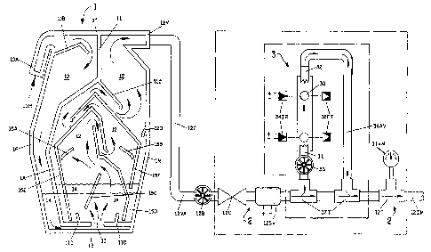
BRIEF DESCRIPTION OF THE DRAWING
FIG. 1. is a longitudinal sectional view showing a schematic air flow passing
through an Air-Power Booster system of the invention as it continues towards
the
intake manifold of an internal combustion engine (not shown).
DETAILED DESCRIPTION OF THE PREFERRED EMBODIMENTS
Fig. 1 schematically depicts an Air-Power Booster system of the invention,
which
includes an air-vacuum liquid compensation device 1, accessories to control
and
regulate the air-vacuum line 12B, 12C, 12SV, and 11 VM which allow adequate
calibration, installation and use of the system in different types of internal
combustion engines, and an optional air speed-flow remote electronic indicator
device 3.
1 ) The air-vac gum liquid compensation device 1, called in short the Booster
1,
has, in the non-limiting example illustrated in cross-section through a center
thereof, has a planar front face and rear face and an asymmetric decagonal
form
due to its internal labyrinth configuration, and is made of a molded polymer
container, having exterior measurements of: height 138 mm, width 90 mm, and
depth 65 mm. The external walls have 3 mm thickness, while the internal
deflection wails have 2 mm thickness. The booster 1 includes an inlet nozzle
and
an outlet nozzle, each having a 3l8 inch I.D., the inlet 10A being inclined
downward, and the outlet 12V being disposed substantially horizontally.
tntemally,
booster 1 is divided by an irregular central wall 11 extending from the top
wall 1T
towards the bottom wall 1 B of the booster 1. Wall 11 does not reach the
bottom
WO 97/Z2793 CA 0 2 2 4 017 9 19 9 8 - 0 6 -12 p~~s96/20003
-18-
wall 1 B. The horizontal portion of wall 11 has a central opening or hole 13
having
a diameter of 3/8 inch. There is a 3-8 mm gap between the bottom wall 1 B and
the horizontal portion of wall 1 1. The horizontal portion of wall 1 1 is
joined to the
rear wall 1 R which extends from the outlet nozzle 12V downward to the bottom
wall 1 B of booster 1.
This configuration creates the liquid compensation chamber 12 which is
contained
in the booster 1 while at the same time it creates the atmospheric pressure
chamber 10, chambers 10 and 12 being divided by the central wall 11 which has
at its bottom a pair of smaller deflectors 11 D and the 3/8 inch ID central
opening
13 interconnecting fluidly the atmospheric pressure chamber 10 with the liquid
compensation chamber 12. When the engine is not running (turned off)
compensating liquid 14 is found occupying partially the lower portions of both
chambers 1 O and 12, but when the engine is turned on (running) the
compensating
liquid 14 will migrate from the chamber 10 through the central opening 13
raising
its internal level in the liquid compensation chamber 12. On the other hand,
internally the liquid compensation chamber contains two small deflectors 15A
and
15B, one central deflector 15C partially immersed in the compensating liquid
14,
all of them inclined, and three irregular deflectors 15D, 15E, and 15F with
their
lower ends inside the liquid compensator 14. The upper ends of each irregular
deflector 15D, 15E and 15F are located above and covering each other, whereby
deflector 15D is below deflector 15E, and deflector 15E is below deflector
15F,
while the central wall 11 has an upper deflector 11 C disposed above and
covering
deflector 15F and at the same time covering all of the upper ends of the
deflectors
15D, 15E and 15F. None of the deflectors are joined to each other, but each
deflector is fixed to the inner faces of the booster 1.
At the front wall 1 F of the high pressure chamber 10, close to the inlet 1
OA,
deflector 1 OB is located, while at the rear wall 1 R of the liquid
compensation
chamber 12 a small further deflector 12D is located. The general function of
each
deflector is to make manageable the high speed flow of air under vacuum
leaving
the compensatin~~ liquid 14, while deflecting the compensating liquid 14 which
' W097/22793 CA 02240179 1998-06-12
PCT/US96/20003
> ,
-19-
passes into the liquid compensation chamber 12. Such management of the flows
of both air and liquid should be highly efficient to avoid migration of the
compensating liqt.iid 14 toward outlet nozzle 12V and this assures the exit of
a
clean liquid-free <3ir flow through the outlet nozzle 12V.
As explained above, the body of compensating liquid 14 contained in the
booster
1 acts by working as a non-restrictive dynamic valve because it is open and
closed
at the same time, where on one side of the compensating liquid 14 there is
atmospheric pressure, while on the opposite side of the compensating liquid 14
there is low pressure resulting in a vacuum. The main function of the booster
is
to draw air from the,ambient (at barometric pressure) and to supply the air to
the
intake manifold as a stable air flow at greatly reduced pressure.
The outlet nozzle 12V is 3/8 inches in internal diameter and is joined by a
translucent flexible hose 12T to the control-regulating valves of the air
flow. These
are a spherical by-pass valve 12B, optional check valve 12C, optional solenoid
12SV, optional re-note observation device 3 installed on a pair of T-junctions
37T,
and optional vacuum-meter 11 VM installed on a T-junction 12T, each having 3/8
inch ID, conforming to the vacuum source-air outlet line 12VA, which ends with
the connector 12 IM of the intake manifold (not shown). In some cases there is
no connection available in the intake manifold for line 12VA. As an
alternative, the
connection could be made by placing a T-junction in conjunction with the
Positive
Crank-case Ventilating system (pcv valve/standard for all vehicles). The
vacuum
source - compensated air outlet line 12VA supplies a negative vacuum low
pressure
(sudden strong pull) to the outlet nozzle 12V located at the top rear of the
booster
1, aspirating freely the internal volume available from the liquid
compensation
chamber 12 equivalent to 70% of the total volume of the compensation chamber
12, since the rei~sining 30% is occupied by the volume of the compensating
liquid
14, where the 3/8" tD central opening 13 is submerged approximately at a depth
of one inch beloLV the surface of the compensating liquid 14. Since starting
the
engine produces a vacuum low pressure equal to an aspiration around 20 to 27
in.Hg (0.35-0.1 bar) above the liquid surface, and 1 inch below the surface,
there
W097/22793 CA 02240179 1998-06-12
PCT/US96I10003
,.
-20-
is atmospheric f~ : ssure of 1 bar ( 1 bar = ten times higher pressure than
0.1 )
coming from the central opening 13 fluidly communicating with the ambient
pressure chamber 1 O, which receives the incoming air flow 10H through the
inlet
nozzle 1 OA. This implies that the compensating liquid 14 is being pulled from
its
upper surface by vacuum low pressure, and pressed upward by the higher
pressure
of incoming air at atmospheric pressure. Both pressures are separated only by
the
surface tension arid the pressure provided by 1 inch of compensating liquid
14.
Thus, the opposed resistance of the liquid can be considered totally null or
zero.
The compensating liquid forms a non-restrictive valve. The result is the
instant
creation of a high speed air flow drawn from atmospheric ambient, crossing the
compensating liquid 14 and finally exiting through the outlet nozzle 12V, and
subsequently accessing the vacuum source-compensated air line 12VA reaching
the intake manifold. The air flow breaks up into bubbles as it travels through
the
compensating liquid 14 and the air/liquid mixture moves dynamically in the
lower
portions of chamber 12, always being returned downward by the deflectors,
thereby keeping the liquid away from the exit nozzle 12V.
The compensated air flow entering the vacuum source-compensated air line 12V
should be regulated according to the particular characteristics of each engine
in
terms of: internal displacement volume, fuel delivery system, and fuel used.
Outlet
12V is connecte-' to a translucent flexible hose 12T which ends in the intake
manifold connection 121M conforming to the vacuum source-compensated air tine
12VA. To this line 12VA should be connected during installing the control
regulating valves for the compensated air flow: spheric by-pass valve 12B,
check
valve 12C, solenoid 12SV, and vacuum meter 11 VM installed on a T-junction.
Each having 3/8 OD, these ace optional accessories, and could be present in
the
line but are not indispensabte to the performing of the system. Turbo engines
require an indispensable check valve 12C and a solenoid valve 12VS as standard
equipment.
It is important to point out that the booster works under a wide range of
different
pressures depenJing on driving conditions. During conditions of maximum
CA 02240179 2003-07-11
- ~1 -
acceleration (W.O.T.) at wide open throttle, internal reading ofvaeuurn low
pressure comes
close to zero (O its. Hg.) where the engine behaves as an normal engine
without the air power
booster. Here lies the importance of the optional speed-flow remote indicator
device 3, to be
inserted optionally over the vacuum source-compensated air line 12VA. This
includes a pair of
T junctions 37 T, a spherical by-pass valve 33, flexible hose 2GA'~J, and the
electronic device 3
itself. This device 3 includes a transparent tube f2 inch outside diameter.
(O.D.) and 3/$ inch
inside diameter and 2 inches in height. Each end carries a small nor~le 3/8
inch O.1'~.: lower
nozzle 31, upper nazale 32, both nor_zles 31 and 32 being desitmed to make
contact with a metal
sphere 30, but without obstructing the flow of high. speed air. Lower nozzle
31 is fluidly
connected to the by pass valve 33 which regulates the air flow a~t the lower
side, and the upper
nozale 32 is fludly connected to the flexible hose 36~1V {1/4 inch LD~) while
at the same time .is
cottxiected to a T junction 37. The lower nozzle 32 is fluidly connected to
the by-pass valve 33
fluidly connected to tlnother T junction 37. Both T-junctions are optionally
inserted in the
vacuum source compensated air line I 2VA. The by pass valve 33 regulates the
high speed air
flaw through the transparent tube, causing the metal sphere 30 to float in an
antigravity fashion,
Both positions of the metal sphere 30 inside the transparent tube {top and
bottom) are registered
by the electr4niC indicator device 3, which is provided externally with two
infrared diodes 34ITt
and two photo transistors 35FT locateii at apposite sides of the transparent
tube. The metal
sphere 30 will interrupt the infrared ace light and tha interruption will
generate an electrical
signal sent to a bar graph lead (not shown in the drawing) which can be
observed remotely
(example, dashboard). 'The top positior:~ of the mewl sphere represents the
optimal level of fuel
consumption while the bottom position represents the tower level. This way the
operator of the
engine or driver is aided to perform efficiently.
In tests using a booster device and method described herein both the carbon
dioxide emissions
and the lttel consumption were reduced. Tz~ the tables shown below, results
are shown in which a
1996 Ford Taurus and a 1996 Ford Thunderbird went tested without (base line)
and with a
booster device attached.
It9G3l-.~lIU7G
TDO-RED N818_~Il~ v I
W097/22793 CA 02240179 1998-06-12
PCT/US96/20003
-22-
Both the Ford Taurus and the Ford Thunderbird tested were 1996 V-6 models with
electronic fuel-injection systems. The tests were performed by an E.P.A.
approved
Independent Tes+~ng Laboratory. The FTP-75 test is a test used by E.P.A. to
determine fuel emissions, HFET is a test used by E.P.A. ti determine fuel
economy
and HOT 505 is the last portion of the FTP-75 test, simulating city driving in
Los
Angeles.
FTP-75
HC(g/m) CO(g/m) NOx(g/m) C02(g/m) FE(mpg)
TAURUS
Base Line: 0.11 0.92 0.15 420.50 21.02
With Device 0.11 0.90 0.19 365.50 24.16
9~ Change -13.08°~ 14.94°r6
THUNDERBIRD
Base Line: 0.10 0.66 0.09 392.70 22.52
With Device 0.09 0.66 0.09 376.70 23.48
Change -4.07% 4.26%
TAURUS
Base Line: 0.02 0.13 0.04 296.11 29.96
With Device 0.02 0.20 ~ 0.05 244.74 36.21
Change -17.35% 20.88%
THUNDERBIRD
Base Line: 0.02 0.07 0.02 301.00 29.47
With Device 0.02 0.08 0.02 254.70 234.82
~ Change -15.38~6 18.15%
W097/22793 CA 02240179 1998-06-12
PCT/US96/20003
-23-
HOT 505
HC(g/m) CO(g/m) NOx(g/m) C02(glm) FE(mpg)
THUNDERBIRD
Base Line: 0.01 0.03 0.01 363.90 24.39
With Device 0.02 0.01 0.01 285.40 31.09
Change -21.57°~ 27.47%
COMPENSATING LIQUID 14
This liquid performs an important function as the separating medium of the two
opposite pressures: low pressure (vacuum) and high pressure (ambient), each
acting in the same sense. This fact offers the booster 1 a wide range of work
enabling it to supply additional air-oxygen with low pressures providing a
vacuum
of as high as 30 in. Hg and as low as 3 in. Hg. which is the minimum limit for
the
engine to perform similarly to any other engine without the booster.
The only resistance to the air flow as it goes through the compensating liquid
of
the booster 1, is produced by the surface tension of the liquid. Due to its
density
and viscosity, it could be affected by working temperatures. The selected
liquid
must carry out ttiP compensation or stabilization process under any climatic
working conditi«r~.s. Example: mineral oil is very adequate to work at below
zero
temperatures, since it does not freeze and can keep an appropriate viscosity.
Any
engine oil SAE 30 offers appropriate results in more benign climates. Where
temperatures ma',' run above 100°)=, it would be recommended to use
engine oil
SAE 50-60. Oil mixtures are also suitable for use in the booster container.
Other
liquids capable of functioning in this way may also be used. The compensation
liquid is not generally consumed, but it is convenient to replace it
periodically in
order to discard a~~y dust particles retained and accumulated at the bottom of
the
booster. The translucent flexible hoses allow a visual observation of the
internal
level and liquid condition (engine off). To replace the compensating liquid,
all that
must be done is Cc~ disconnect the booster unit, turn it upside down and empty
its
contents. Later, the booster can be filled again, up to the marked level.
W097/2Z793 CA 02240179 1998-06-12 p~NS96/20003
_ ,
-24-
ADDIT10NAL USES OF THE BOOSTER
The properties of each particular liquid, allow the booster 1 to be used as a
way
to supply high concentrations of extra oxygen. Methanol (CH30H), which is
volatile and infla~:.mable, contains 50% by weight of molecular oxygen, and
may
be used in the br,oster as the compensating liquid. Use of methanol will allow
a
flow of air, which provides a load of 50°~ of extra oxygen entering the
combustion
chamber. Therefore, the booster will behave as a chemical supercharger, mostly
applied in modified sport engines. For this special use, the booster must have
an
optional accessory to constantly replace the volume of methanol being consumed
by evaporation. In the same way, the booster can be used to supply any
chemical
liquid having properties which can be advantageous due to their intrinsic
physical-
chemical characteristics.
Although a preferred embodiment of the invention has been herein described, it
will
be appreciated that some changes in structure can be effected without
departure
from the basic principles of the invention. Such changes are deemed to be
included in the spirit and scope of the invention as defined by the appended
claims
and equivalents thereof.