Language selection

Search

Patent 2240797 Summary

Third-party information liability

Some of the information on this Web page has been provided by external sources. The Government of Canada is not responsible for the accuracy, reliability or currency of the information supplied by external sources. Users wishing to rely upon this information should consult directly with the source of the information. Content provided by external sources is not subject to official languages, privacy and accessibility requirements.

Claims and Abstract availability

Any discrepancies in the text and image of the Claims and Abstract are due to differing posting times. Text of the Claims and Abstract are posted:

  • At the time the application is open to public inspection;
  • At the time of issue of the patent (grant).
(12) Patent: (11) CA 2240797
(54) English Title: STRETCH COMPENSATION IN A HOISTING SYSTEM FOR A DERRICK
(54) French Title: COMPENSATION DE TRACTION DANS UN DISPOSITIF DE LEVAGE DE DERRICK
Status: Expired and beyond the Period of Reversal
Bibliographic Data
(51) International Patent Classification (IPC):
  • E21B 19/02 (2006.01)
  • B66B 07/10 (2006.01)
  • E21B 19/084 (2006.01)
  • E21B 19/086 (2006.01)
  • E21B 19/16 (2006.01)
(72) Inventors :
  • VATNE, PER (Norway)
(73) Owners :
  • AKER KVAERNER MH AS
(71) Applicants :
  • AKER KVAERNER MH AS (Norway)
(74) Agent: MCCARTHY TETRAULT LLP
(74) Associate agent:
(45) Issued: 2004-12-14
(86) PCT Filing Date: 1996-12-23
(87) Open to Public Inspection: 1997-07-10
Examination requested: 2001-12-03
Availability of licence: N/A
Dedicated to the Public: N/A
(25) Language of filing: English

Patent Cooperation Treaty (PCT): Yes
(86) PCT Filing Number: PCT/NO1996/000310
(87) International Publication Number: NO1996000310
(85) National Entry: 1998-06-18

(30) Application Priority Data:
Application No. Country/Territory Date
955310 (Norway) 1995-12-27

Abstracts

English Abstract


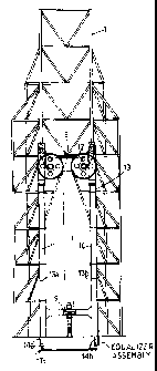
An apparatus for a derrick, comprising two or more hydraulic piston-cylinder
arrangements (10, 11) for raising and lowering a yoke (8) which travels on
guide rails
(7) in the derrick (1) itself, where two or more wire lines (13) are strung
over sheaves (12)
rotatably attached to the yoke. The wire lines (13) are attached at one end
thereof to the
top drive (9) and at the other end thereof are secured to an attachment point
(14a, 14b)
adjacent to a drill floor (2), said two or more wire lines being run in two
sets (13a, 13b)
of lines. The attachment points (14a, 14b) for each wire set are connected to
a tension
equalizer assembly to equalize differences in tension in the wire lines.


French Abstract

L'invention porte sur un appareil destiné à un derrick, comportant deux mécanismes hydrauliques à piston-cylindre (10, 11), destinés à faire monter et descendre un joug (8) se déplaçant sur des rails de guidage (7) situés sur le derrick (1) lui-même, deux filins (13) ou davantage étant tendus sur des poulies (12) montées rotatives sur le joug. Les filins (13) sont attachés par l'une de leurs extrémités à un mécanisme supérieur d'entraînement (9) et assujettis par l'autre extrémité à un point de fixation (14a, 14b) contigu au plancher (2) d'un outil de forage, lesdits filins, deux à tout le moins, étant agencés en deux ensembles (13a, 13b). Les points de fixation (14a, 14b) de chaque ensemble de filins sont rattachés à un ensemble d'égalisation des tensions destiné à équilibrer des différences de tension existant entre les filins.

Claims

Note: Claims are shown in the official language in which they were submitted.


5
Claims
1. An apparatus for a derrick, comprising two or more hydraulic piston-
cylinder
arrangements (10, 11) for raising and lowering a yoke (8) which travels on
guide rails
(7) in the derrick (1) itself, where two or more wire lines (13) are strung
over sheaves
(12) rotatably attached to the yoke, which wire lines (13) are attached at one
end thereof
to the top drive (9) and at the other thereof are secured to an attachment
point (14a, 14b)
adjacent to a drill floor (2), said two or more wire lines being run in two
sets (13a, 13b)
of lines, the attachment points (14a, 14b) for which are spaced apart,
characterized in that the attachment point (14a, 14b) for each set of wire
lines
is connected to its respective end of at least one balance bar joined to the
drill floor (2),
which bar is movable in order to equalize different tensions in the wire lines
(13).
2.
The apparatus in accordance with claim 1, characterized in that the wire lines
(13) are connected to the balance bar (24) via an angle lever (20a, 20b) for
each wire set
(13a, 13b), which angle lever (20a, 20b) is pivotably mounted in the drill
floor (2), that
the wires are attached to one arm (21) of the angle level (20a, 20b) and that
the balance
bar (24) is attached to the other arm (22) of the angle lever (20a, 20b).
3.
The apparatus in accordance with claim 1 or 2,
characterized in that the wire set (13a, 13b) is connected to the angle lever
(20a, 20b) via a wire set balance arm (18), said wires (13) being attached to
the ends of
the wire set balance arm (18), while the angle lever is attached to the center
of the wire
set balance arm (18).
4.
The apparatus in accordance with claim 1, 2 or 3,
characterized in that the wire set (13a, 13b) is connected to the wire set
balance arm (18) via two wire pair balance arms (16), said wires (13) being
attached to
the ends of the wire pair balance arms (16), whereas the wire set balance arm
(18) is
attached to the center of the wire pair balance arms (16).

Description

Note: Descriptions are shown in the official language in which they were submitted.


CA 02240797 1998-06-18
WO 97124507 PCT/N096100310
STRETCH CO~~IPENSATION IN A HOISTING SYSTEM FOR A DERRICK.
The present invention relates to an apparatus for a derrick, comprising two or
more
hydraulic piston-cylinder arrangements for raising and lowering a yoke which
travels on
guide rails in the derrick itself, where two or more wire lines are strung
over sheaves
rotatably attached to the yoke, said wires being attached at one end thereof
to the top
drive and at the other end thereof being secured to an attachment point
adjacent to a drill
floor, said two or more wires being run in two sets of lines, the attachment
points of
which wire sets are spaced apart.
io
A dernck structure which was developed in 1987 by the present inventor and
which has
shown great promise embodies the RamRig TM concept. Two hydraulic piston-
cylinder arrangements are used in the derrick for raising and lowering the
drill string.
The cylinders operate between the drill floor and a yoke which travels on
guide rails in
~ s the derrick itself. The advantages of this concept are numerous, some of
the most
important being that it is possible to place the drill floor at a higher level
than the
platform floor, that a derrick may be constructed having a significantly lower
air
resistance, that a higher level of safety and longer lifetime are attained for
the most
expensive components of the dernck.
Since it is possible to position the drill floor higher than the platform
floor, pipe
handling is significantly simplified. There is no longer any need to arrange
the pipe
handling equipment at a high level in the dernck. All pipe handling equipment
may be
placed on the platform floor and the drill floor.
30
The object of the present invention is to solve important, practical problems
in the
realization of the RamRigTM concept. This objective is achieved by means of
the
features apparent from the characterizing clause of the subsequently disclosed
claim 1.
The invention will now be explained in greater detail with reference to the
enclosed
drawings, where
Figure 1 shows a RamRigTM derrick in every essential detail;
Figure 2 shows the derrick schematically, viewed from the side;

CA 02240797 1998-06-18
WO 97124507 PCTIN096/00310
2
Figure 3 shows the derrick schematically, viewed from the front, with the top
drive in its
lowermost position;
Figure 4 shows the derrick schematically, viewed from the front, with the top
drive in its
s uppermost position:
Figure 5 shows the tension equalizer assembly seen from the side,
Figure 6 shows a portion of the tension equalizer assembly, seen from the
front, and
~o
Figure 7 shows a portion of the tension equalizer assembly seen from above.
Figure 1 shows a dernck 1 positioned on a drill floor 2. The drill floor is
arranged at a
higher level than the platform floor 3, enabling the pipe handling equipment 4
to be
is placed mainly between the platform floor 3 and the drill floor 2. Dernck 1
is
substantially gantry-shaped, having gantry legs 5, 6. Guide rails 7 for a yoke
8 and a
top drive 9 run along each gantry leg S, 6. Hydraulic piston-cylinder
arrangements 10,
11 are positioned so as to extend along each gantry leg S, 6, and operate
between drill
floor 2 and yoke 8, for moving yoke 8 vertically along guide rails 7.
25
The yoke 8 is provided with a plurality of sheaves 12, preferably four, for
running the
wire lines 13. Wire lines 13 extend from drill floor 2 along each gantry leg
5, 6, over
sheaves 12 and down to top drive 9. By retracting and extending the piston-
cylinder
arrangement 10, 11, it is thereby possible to raise and lower top drive 9.
In Figures 2, 3 and 4 the function of the hoisting system is seen most
clearly. In Figures
2 and 3 the piston-cylinder arrangement 10, 11 is shown in a completely
retracted state.
Top drive 9 is then at its lowermost position, quite close to the drill floor.
Yoke 8 is at
the upper end of the piston-cylinder arrangement.
When the pistons in the piston-cylinder arrangement are extended, yoke 8 is
lifted along
guide rails 7 up to the top of derrick 1. The top drive is then lifted, as a
result of the
transmission generated as wire lines 13 are run over sheaves 12, from its
position
adjacent drill floor 2 to a position directly below yoke 8. The height to
which top drive
3s 9 is hoisted is thus the double of that to which yoke 8 is lifted.

CA 02240797 1998-06-18
WO 97124507 PCT/N096100310
3
There may, for example, be as many as eight wire lines 13 arranged in the
hoisting
apparatus described above, with the wire lines being strung two by two in
their
respective tracks over the same sheave I2. Four sheaves are arranged in pairs
at each
end of yoke 8. Wire lines 13 are thus arranged in two sets 13a and 13b,
extending from
s attachment points 14a and 14b at drill floor 2, over sheaves 12 and down to
top drive 9.
Attachment points 14a and 14b are spaced apart horizontally by a distance
corresponding approximately to the length of yoke 8.
Wire lines 13 will seldom be of exactly the same length or exhibit exactly the
same
~o elasticity module. Therefore, as a rule, there will be different tensions
in the wire lines
13. This can result in increased strain on some of the individual wires, which
in turn
increases the wear and tear thereof.
To help alleviate this problem, there is proposed according to the invention
the
is provision of a tension equalizer assembly 15 at the point of attachment 14
of wire lines
13 adjacent drill floor 2.
The tension equalizer assembly I S is seen most clearly in Figures 5-7. In
Figure 5 we
see that wire lines 13 in each wire set are rotatably attached in pairs to
their respective
zo ends of a wire pair balance arm 16 for each pair of wires. Each wire pair
balance arm 16
is pivotably attached, via its respective wire pair bar 17 extending downward
from the
center of wire pair balance arm I6, to one end of a wire set balance arm I 8.
Wire set
balance arm 18 is in tum pivotably attached, via a wire set bar 19 extending
downward
from the center of wire set balance arm 18, to an angle lever 20a, which is
best seen in
is Figure 6.
Angle lever 20a consists of a horizontal arm 21, extending in the direction of
the
opposing wire set 13b, and two vertical downward-oriented arms 22. Arms 22 are
firmly connected to arm 21 via two horizontal bars 23, which extend
perpendicularly to
3o arm 21, and arms 22 are firmly connected to arm 21 at the end thereof
opposite to the
attachment point for wire set bar 19, and to arms 22 at the uppermost end
thereof.
Angle lever 20a is pivotably mounted in drill floor 2 about bar 23. The
lowermost ends
of arms 22 are rotatably connected to their respective balance bar 24. Balance
bars 24
extend horizontally in a direction toward the opposing wire set I3b. Her,
balance bars
3s 24 are rotabably connected to an angle lever 20b corresponding to angle
lever 20a. In
other respects the tension equalizer assembly 15 has an identical form at
attachment
point I4b for wire set 13b.

CA 02240797 1998-06-18
WO 97/24507 PCT/N096/00310
4
If, for example, one of the wires 13 in wire set 13a were to be slightly
shorter than the
other wires 13, this would pull on wire pair balance arm 16, causing it to
assume a tilted
position, with the end to which the shortest wire is attached being furthest
up. If both of
s the wires 13 in this pair of wire lines were to be shorter than the wires
attached to the
other wire pair balance arm 16 in wire set 13a, then wire set balance arm 18
would also
assume a tilted position.
If the wire lines in wire set 13a together exert a greater tension than the
wire lines in
~o wire set 13b, then the arm 21 of angle lever 20a would be drawn upward
causing the
arms 22 and therewith also balance bars 24 to be drawn in a direction away
from the
other wire set 13b. The opposite angle lever 20b would thereby also be turned
about its
attachment point in drill floor 2, thus exerting tension on wire set 13b,
which tension is
further equalized between the individual wire lines in wire set 13b in the
same manner
~s as for wire set 13a.
With the aid of the above described wire tension equalizer assembly 1 S, it is
possible to
avoid overloading andlor premature wear and tear on individual wires. It is
also
possible to reduce the demands for tolerance with respect to, for example, the
length of
zo the wires. Furthermore, it is possible to utilize a plurality of thinner
and more flexible
wires instead of a few heavier wires, inasmuch as the tension may be uniformly
distributed among all of the wires.
Although, in the above, there is described a tension equalizer assembly
comprising a
2s plurality of balance arms, it is clear that with the use of fewer wires,
there would be no
need for as many arms. When using only one wire line on each side, for
example, this
one wire could, of course, be connected directly to arm 21.

Representative Drawing
A single figure which represents the drawing illustrating the invention.
Administrative Status

2024-08-01:As part of the Next Generation Patents (NGP) transition, the Canadian Patents Database (CPD) now contains a more detailed Event History, which replicates the Event Log of our new back-office solution.

Please note that "Inactive:" events refers to events no longer in use in our new back-office solution.

For a clearer understanding of the status of the application/patent presented on this page, the site Disclaimer , as well as the definitions for Patent , Event History , Maintenance Fee  and Payment History  should be consulted.

Event History

Description Date
Time Limit for Reversal Expired 2016-12-23
Letter Sent 2015-12-23
Letter Sent 2007-02-22
Inactive: Multiple transfers 2007-01-09
Inactive: IPC from MCD 2006-03-12
Grant by Issuance 2004-12-14
Inactive: Cover page published 2004-12-13
Pre-grant 2004-10-04
Inactive: Final fee received 2004-10-04
Notice of Allowance is Issued 2004-04-15
Letter Sent 2004-04-15
Notice of Allowance is Issued 2004-04-15
Inactive: Approved for allowance (AFA) 2004-03-31
Letter Sent 2002-01-09
Request for Examination Received 2001-12-03
Request for Examination Requirements Determined Compliant 2001-12-03
All Requirements for Examination Determined Compliant 2001-12-03
Amendment Received - Voluntary Amendment 2001-12-03
Inactive: IPC assigned 1998-09-28
Inactive: First IPC assigned 1998-09-28
Classification Modified 1998-09-28
Inactive: IPC assigned 1998-09-28
Inactive: Notice - National entry - No RFE 1998-09-02
Application Received - PCT 1998-08-26
Application Published (Open to Public Inspection) 1997-07-10

Abandonment History

There is no abandonment history.

Maintenance Fee

The last payment was received on 2003-11-27

Note : If the full payment has not been received on or before the date indicated, a further fee may be required which may be one of the following

  • the reinstatement fee;
  • the late payment fee; or
  • additional fee to reverse deemed expiry.

Patent fees are adjusted on the 1st of January every year. The amounts above are the current amounts if received by December 31 of the current year.
Please refer to the CIPO Patent Fees web page to see all current fee amounts.

Owners on Record

Note: Records showing the ownership history in alphabetical order.

Current Owners on Record
AKER KVAERNER MH AS
Past Owners on Record
PER VATNE
Past Owners that do not appear in the "Owners on Record" listing will appear in other documentation within the application.
Documents

To view selected files, please enter reCAPTCHA code :


To view images, click a link in the Document Description column. To download the documents, select one or more checkboxes in the first column and then click the "Download Selected in PDF format (Zip Archive)" or the "Download Selected as Single PDF" button.

List of published and non-published patent-specific documents on the CPD .

If you have any difficulty accessing content, you can call the Client Service Centre at 1-866-997-1936 or send them an e-mail at CIPO Client Service Centre.


Document
Description 
Date
(yyyy-mm-dd) 
Number of pages   Size of Image (KB) 
Representative drawing 1998-09-28 1 13
Description 1998-06-17 4 198
Abstract 1998-06-17 1 58
Claims 1998-06-17 1 46
Drawings 1998-06-17 5 167
Representative drawing 2004-11-14 1 12
Notice of National Entry 1998-09-01 1 209
Courtesy - Certificate of registration (related document(s)) 1998-09-01 1 140
Reminder - Request for Examination 2001-08-26 1 129
Acknowledgement of Request for Examination 2002-01-08 1 178
Commissioner's Notice - Application Found Allowable 2004-04-14 1 161
Maintenance Fee Notice 2016-02-02 1 170
PCT 1998-06-17 7 273
Fees 2002-11-26 1 34
Fees 2003-11-26 1 26
Fees 1999-12-01 1 43
Fees 2000-11-23 1 40
Fees 2001-12-02 1 35
Correspondence 2004-10-03 1 27
Fees 2004-11-30 1 28