Language selection

Search

Patent 2242043 Summary

Third-party information liability

Some of the information on this Web page has been provided by external sources. The Government of Canada is not responsible for the accuracy, reliability or currency of the information supplied by external sources. Users wishing to rely upon this information should consult directly with the source of the information. Content provided by external sources is not subject to official languages, privacy and accessibility requirements.

Claims and Abstract availability

Any discrepancies in the text and image of the Claims and Abstract are due to differing posting times. Text of the Claims and Abstract are posted:

  • At the time the application is open to public inspection;
  • At the time of issue of the patent (grant).
(12) Patent: (11) CA 2242043
(54) English Title: ANTI-DERAILING MECHANISM FOR TRACK MOUNTED BATH DOORS
(54) French Title: MECANISME ANTI-DERAILLEMENT POUR PORTES DE BAIGNOIRE MONTEES SUR GLISSIERE
Status: Expired and beyond the Period of Reversal
Bibliographic Data
(51) International Patent Classification (IPC):
  • E05D 15/06 (2006.01)
  • A47K 3/34 (2006.01)
  • E05D 11/06 (2006.01)
  • E06B 3/46 (2006.01)
(72) Inventors :
  • KURTH, MICHAEL J. (United States of America)
(73) Owners :
  • KOHLER CO.
(71) Applicants :
  • KOHLER CO. (United States of America)
(74) Agent: MARKS & CLERK
(74) Associate agent:
(45) Issued: 2003-04-01
(86) PCT Filing Date: 1996-12-19
(87) Open to Public Inspection: 1997-07-17
Examination requested: 2000-12-13
Availability of licence: N/A
Dedicated to the Public: N/A
(25) Language of filing: English

Patent Cooperation Treaty (PCT): Yes
(86) PCT Filing Number: PCT/US1996/020708
(87) International Publication Number: WO 1997025506
(85) National Entry: 1998-07-02

(30) Application Priority Data:
Application No. Country/Territory Date
08/582,859 (United States of America) 1996-01-04

Abstracts

English Abstract


A door system (15) for a bathing enclosure which includes a track (22)
extending above an opening of the enclosure with the track having a rail (34)
with an upper surface having a longitudinal groove (38). A door (31) has first
and second rollers (42, 72) which ride in the rail groove (38), so that the
door (31) is suspended from and slidable along the track (22). A separate stop
is associated with each roller (42, 72) with each stop having a locking
bracket (60) fixed to the door (31) and a member (64, 74) is movably attached
to the locking bracket. The members (64, 74) are adjustable between a first
position at which the respective roller (42, 72) may be removed from the
groove (38) and a second position at which the member strikes the track (22)
before the respective roller (42, 72) can be removed from the groove (38).


French Abstract

Système (15) de porte pour enceinte de baignoire comprenant une glissière (22) s'étendant au-dessus d'une ouverture de l'enceinte, cette glissière étant pourvue d'un rail (34) comportant dans sa surface supérieure une rainure longitudinale (38). Une porte (31) possède des première et seconde roulettes (42, 72) qui chevauchent la rainure (38) de sorte que la porte (31) soit suspendue et puisse coulisser le long de la glissière (22). Une butée séparée est associée à chaque roulette (42, 72) et comporte une tige de verrouillage (60) fixée à la porte (31), et un élément (64, 74) est fixé amovible à la tige de verrouillage. Ces éléments (64, 74) peuvent se régler entre une première position dans laquelle la roulette respective (42, 72) peut être retirée de la rainure (38) et une seconde position dans laquelle l'élément heurte la glissière (22) avant que la roulette respective (42, 72) puisse être retirée de la rainure (38).

Claims

Note: Claims are shown in the official language in which they were submitted.

5
CLAIMS
1. A door system for a bathing enclosure which has
an opening, said door system comprising a track extending
above the opening and having a rail, a door, at least one
roller attached to the door and engaging the rail, so
that the door is suspended from and slidable along the
track, and a stop attached to door and moveable
vertically with respect to the door between a first
position at which the door may be removed from the track
and a second position at which the stop strikes the track
preventing removal of the door, said stop comprising a
locking bracket fixed to the door with a threaded
aperture extending through the locking bracket; and a
threaded rod inserted into the threaded aperture.
2. A door system for a bathing enclosure which has
an opening, said door system comprising a track extending
above the opening and having a rail with an upper surface
that has a groove therein, a door, first and second
rollers attached to the door and riding in the groove of
the rail, so that the door is suspended from and slidable
along the track, and a first stop having a first locking
bracket fixed to the door with a first threaded aperture
extending through the first locking bracket, and having a
first threaded and inserted into the first threaded
aperture and moveable with respect to the first locking
bracket between a first position at which the first
roller may be removed from the groove and a second
position at which the first threaded rod strikes the
track before the first roller can be removed from the
groove.
3. The door system as recited in claim 2, wherein

6
the threaded rod strikes the rail to the second position
before the first roller can become removed from the
groove.
4. The door system as recited in claim 2, further
comprising a second stop having a second locking bracket
fixed to the door with a second threaded aperture
extending through the second locking bracket, and having
a second threaded rod inserted into the second threaded
aperture and moveable with respect to the second locking
bracket between one position at which the second roller
may be removed from the groove and another position at
which the second threaded rod strikes the track before
the second roller can be removed from the groove.
5. A door system for a bathing enclosure which has
an opening, said door system comprising a track extending
above the opening and including a first rail and a second
rail, each rail having an upper surface that has a groove
therein, first and second doors, first and second rollers
attached to the first door and riding in the groove of
the first rail, so that the first door is suspended from
and slidable along the track, third and fourth rollers
attached to the second door and riding in the groove of
the second rail, so that the second door is suspended
from and slidable along the track, a first stop including
a first locking bracket fixed to the first door with a
first threaded aperture extending through the first
locking bracket, and having a first threaded rod inserted
into the first threaded aperture and moveable vertically
with respect to the first locking bracket between one
position at which the first roller may be removed from
the groove in the first rail and another position at

7
0
which the first threaded rod strikes the track before the
first roller can be removed from the groove in the first
rail, and a second stop including a second locking
bracket fixed to the second door with a second threaded
aperture extending through the second locking bracket,
and having a second threaded rod inserted into the second
threaded aperture and moveable vertically with respect to
the second locking bracket between first position at
which the third roller may be removed from the groove in
the second rail and a second position at which the second
threaded rod strikes the track before the third roller
can be removed from the groove in the second rail.

Description

Note: Descriptions are shown in the official language in which they were submitted.


CA 02242043 1998-07-02
WO 97/25506 PCT/US96120708
-1-
ANTI-DERAILING MECHANISM FOR TRACK MOUNTED BATH DOORS
Backctround Of The Invention
The present invention relates to sliding doors of the
type commonly used as part of a shower or tub enclosure; and
more particularly to such doors that are suspended from and
slidable along an overhead track.
Tub and shower enclosures often have an opening that is
closed with a pair of sliding doors. A common door assembly
has a lower track mounted on the rim of the tub or shower pan
and another track mounted directly overhead. Each door
slides in separate channels within the tracks and is able to
slide past the other door.
In one version of this type of door assembly, a pair of
rollers are mounted on the door and ride in a groove in the
overhead track. The rollers enable the door to glide easily
in a horizontal direction along the overhead track. However,
a bather could inadvertently raise the door in a manner that
causes the rollers to dislodge from the rail and allows the
door to fall into or out of the tub.
In addition, the design allows the user to tip the door
inward to clean the door and the lower track. It also is
desirable to prevent the door from coming off the overhead
track while the door is tipped for cleaning.
Summary Of The Invention
The general object of the present invention is to
provide a door assembly for a tub or shower enclosure in
which a door is suspended from an overhead track in a manner
that allows the door to slide along the track.
Another object is to provide such a sliding door
assembly with a mechanism that restricts upward movement of
door thereby preventing the door from derailing from the
overhead track.
These objects are fulfilled by a door system for a
bathing enclosure which includes a track with a rail
extending above an opening of the bathing enclosure. A door
panel has at least one roller attached thereto and engaging

CA 02242043 2001-09-10
2
the rail, so that the door is suspended from and slidable
along the track. A stop is attached to the door in a
manner that allows the stop to be moved vertically with
respect to the door. In one position of the stop, the
door may be removed from the track and in another
position the stop strikes the track before the door is
able to disengage the track. The stop comprises a
locking bracket fixed to the door and having a threaded
aperture which extends through the locking bracket. A
threaded rod inserted into the aperture. By turning the
rod within the aperture, the spacing between the rod and
the track can be adjusted to either provide clearance for
the door to be removed from the track or prevent such
removal by not providing a sufficient amount of
clearance.
Brief Description of the Drawings
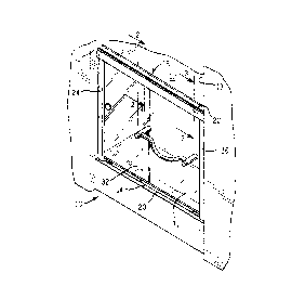
Figure 1 is a pictorial representation of a shower
enclosure with a sliding door system which incorporates
the present invention;
Figure 2 is a cross-sectional view through the
overhead track of the door system along line 2-2 in
Figure 1; and
Figure 3 is a cross-sectional view through the
overhead track of the door system along line 3-3 in
Figure 1.
Detailed Description of the Invention
With initial reference to Figure 1, a bath tub 10 is
located in a recess formed by walls 11, 12 and 13.
Although the present door system is being described in
the context of a bath tub, it also can be applied to
showers and other bathing enclosures. The bath tub 10

CA 02242043 2001-09-10
2a ,
includes a front rim 14 extending between walls 11 and
13.
The tub recess is closed by a door system 15 having
a lower track 20 mounted on front tub rim 14 and an
overhead track 22 which extends directly over the lower
track between walls 11 and 13. A separate wall jam 24 or
26 is mounted vertically along each side wall 11 or 13,
respectively, between the two tracks 20 and 22. The
tracks 20 and 22 and

CA 02242043 1998-07-02
WO 97/2550b PCT/US96/20708
-3-
wall jams 24 and 26 define an opening of the tub enclosure.
Two glass-panel doors 31 and 32 are suspended from the
overhead track 22 in the enclosure opening and extend
downward to the front rim 14 of the tub 10 into the lower
track 20. The outer door 31 and the inner door 32 can slide
in either direction past one another along the two tracks 20
and 22 to create a passageway adjacent either side wall 11
or 13 through which a bather enters and exits the shower
enclosure 10.
With reference to Figure 2, the overhead track 22 is
formed by an elongated channel member 35 with an inverted
U-shaped cross section and having outer and inner horizontal
rails 34 and 36 within the opening of the channel. Each rail
34 and 36 has a longitudinal groove 38 and 40, respectively,
within which rollers 42 and 44 ride. Roller 42 is mounted on
an axle 48 attached to a fastener 46 that extends through a
hole near the top edge of a mounting bracket 52 fixed to the
outer door 31. The other illustrated roller 44 is mounted on
axle 49 that is connected by a fastener 47 that extends
through a mounting bracket 54 attached to the inner door 32.
Two roller assemblies of this design are spaced apart
along the top edge of each door 31-32. The rollers for the
inner door 32 ride on the inner rail 36, while the outer door
rollers engage the outer rail 34.
Door fasteners 56 and 58, which hold the mounting
brackets 52 and 54, respectively, on the two doors 31 and 32,
also attach locking brackets 60 and 62 to those doors,
although the combination of a mounting bracket and a locking
bracket could be fabricated as a single piece. Each locking
bracket 60 and 62 is L-shaped with one end of a vertical leg
61 attached to the respective door 31 or 32. The horizontal
leg 63 of each locking bracket extends over the top of the
respective door, through a hole in the respective mounting
bracket, and under the rail 34 or 36 on which the
corresponding door rides. The end 67 of the horizontal 63
leg that is under the rail has a threaded aperture there
through and a threaded rod 64 or 66 is received in the
threaded aperture of the locking bracket 60 or 62,

CA 02242043 1998-07-02
WO 97/25506 PCT/US96/20708
-4-
respectively. The lower end of each threaded rod 64 and 66
has a hexagonal aperture 65 for receiving an allen wrench in
order to turn the rod in the locking bracket aperture.
Figure 3 shows the other roller 72 with its mounting
bracket for the outer door 31. The inner door 32 has a
similar second roller near wall jam 24.
When the outer door 31, for example, is being assembled
onto the overhead track 22, the threaded rods 64 and 74 are
turned as far downward as possible, i.e. to a position that
creates the largest gap between the rods and rollers 42 and
72. The outer door then is slid upward into the track 22 so
that the rollers pass between the two rails 34 and 36 and
then into the groove 38 in the outer rail 34. Once both
rollers 42 and 72 are located in the groove 3B, the installer
inserts an allen wrench into the hexagonal aperture 65 of
each threaded rod 64 and 74. Each threaded rod then is
turned to raise it toward rail 34 and decrease the gap
between the rod and that rail. The threaded rods are turned
until each gap is less than the depth of the groove 38 in the
track rail 34, while leaving a small spacing to permit the
outer door 32 to slide along the track 22.
In this state, when the outer door 31 is raised upward,
the top ends 68 of threaded rods 64 and 74 strike the
underside of rail 34 before the rollers 42 and 72 are able to
leave the rail groove 38. Thus threaded rods 64 and 74 act
as stops preventing the outer door 3Z from derailing from the
track 22. The outer door can be removed from the track by
lowering the threaded rods in the respective locking bracket
apertures and reversing the steps of the assembly process.
The inner door 32 functions in a like manner.

Representative Drawing
A single figure which represents the drawing illustrating the invention.
Administrative Status

2024-08-01:As part of the Next Generation Patents (NGP) transition, the Canadian Patents Database (CPD) now contains a more detailed Event History, which replicates the Event Log of our new back-office solution.

Please note that "Inactive:" events refers to events no longer in use in our new back-office solution.

For a clearer understanding of the status of the application/patent presented on this page, the site Disclaimer , as well as the definitions for Patent , Event History , Maintenance Fee  and Payment History  should be consulted.

Event History

Description Date
Time Limit for Reversal Expired 2013-12-19
Letter Sent 2012-12-19
Inactive: IPC from MCD 2006-03-12
Grant by Issuance 2003-04-01
Inactive: Cover page published 2003-03-31
Inactive: Final fee received 2003-01-03
Pre-grant 2003-01-03
Notice of Allowance is Issued 2002-07-03
Letter Sent 2002-07-03
Notice of Allowance is Issued 2002-07-03
Inactive: Prior art correction 2002-07-03
Inactive: Approved for allowance (AFA) 2002-06-20
Amendment Received - Voluntary Amendment 2001-09-10
Letter Sent 2001-01-08
Request for Examination Requirements Determined Compliant 2000-12-13
All Requirements for Examination Determined Compliant 2000-12-13
Request for Examination Received 2000-12-13
Inactive: Single transfer 1998-12-04
Inactive: IPC assigned 1998-10-09
Inactive: First IPC assigned 1998-10-09
Inactive: IPC assigned 1998-10-06
Classification Modified 1998-10-06
Inactive: IPC assigned 1998-10-06
Inactive: Courtesy letter - Evidence 1998-09-22
Inactive: Notice - National entry - No RFE 1998-09-17
Application Received - PCT 1998-09-09
Application Published (Open to Public Inspection) 1997-07-17

Abandonment History

There is no abandonment history.

Maintenance Fee

The last payment was received on 2002-11-22

Note : If the full payment has not been received on or before the date indicated, a further fee may be required which may be one of the following

  • the reinstatement fee;
  • the late payment fee; or
  • additional fee to reverse deemed expiry.

Please refer to the CIPO Patent Fees web page to see all current fee amounts.

Owners on Record

Note: Records showing the ownership history in alphabetical order.

Current Owners on Record
KOHLER CO.
Past Owners on Record
MICHAEL J. KURTH
Past Owners that do not appear in the "Owners on Record" listing will appear in other documentation within the application.
Documents

To view selected files, please enter reCAPTCHA code :


To view images, click a link in the Document Description column. To download the documents, select one or more checkboxes in the first column and then click the "Download Selected in PDF format (Zip Archive)" or the "Download Selected as Single PDF" button.

List of published and non-published patent-specific documents on the CPD .

If you have any difficulty accessing content, you can call the Client Service Centre at 1-866-997-1936 or send them an e-mail at CIPO Client Service Centre.


Document
Description 
Date
(yyyy-mm-dd) 
Number of pages   Size of Image (KB) 
Cover Page 2003-02-25 1 47
Description 1998-07-02 4 209
Claims 1998-07-02 3 134
Abstract 1998-07-02 1 58
Drawings 1998-07-02 1 41
Cover Page 1998-10-13 1 56
Description 2001-09-10 5 207
Claims 2001-09-10 3 105
Representative drawing 1998-10-13 1 10
Reminder of maintenance fee due 1998-09-14 1 115
Notice of National Entry 1998-09-17 1 209
Courtesy - Certificate of registration (related document(s)) 1999-01-27 1 114
Acknowledgement of Request for Examination 2001-01-08 1 180
Commissioner's Notice - Application Found Allowable 2002-07-03 1 164
Maintenance Fee Notice 2013-01-30 1 170
Correspondence 2003-01-03 1 28
Correspondence 2002-03-18 5 229
PCT 1998-07-02 9 306
Correspondence 1998-09-22 1 29