Language selection

Search

Patent 2242154 Summary

Third-party information liability

Some of the information on this Web page has been provided by external sources. The Government of Canada is not responsible for the accuracy, reliability or currency of the information supplied by external sources. Users wishing to rely upon this information should consult directly with the source of the information. Content provided by external sources is not subject to official languages, privacy and accessibility requirements.

Claims and Abstract availability

Any discrepancies in the text and image of the Claims and Abstract are due to differing posting times. Text of the Claims and Abstract are posted:

  • At the time the application is open to public inspection;
  • At the time of issue of the patent (grant).
(12) Patent Application: (11) CA 2242154
(54) English Title: CONSTRUCTION AND METHOD OF MAKING PROP SHAFT HAVING ENLARGED END SECTIONS
(54) French Title: CONSTRUCTION ET METHODE DE FABRICATION D'UN ARBRE DE TRANSMISSION A SECTIONS D'EXTREMITE ELARGIES
Status: Deemed Abandoned and Beyond the Period of Reinstatement - Pending Response to Notice of Disregarded Communication
Bibliographic Data
(51) International Patent Classification (IPC):
  • F16C 03/02 (2006.01)
  • B60K 17/22 (2006.01)
  • B60K 17/344 (2006.01)
(72) Inventors :
  • BARRETT, MARK S. (United States of America)
  • OLDENBURG, THOMAS J. (United States of America)
(73) Owners :
  • AMERICAN AXLE & MANUFACTURING INC.
(71) Applicants :
  • AMERICAN AXLE & MANUFACTURING INC. (United States of America)
(74) Agent: SMART & BIGGAR LP
(74) Associate agent:
(45) Issued:
(22) Filed Date: 1998-07-03
(41) Open to Public Inspection: 1999-01-07
Availability of licence: N/A
Dedicated to the Public: N/A
(25) Language of filing: English

Patent Cooperation Treaty (PCT): No

(30) Application Priority Data:
Application No. Country/Territory Date
08/888,512 (United States of America) 1997-07-07

Abstracts

English Abstract


An automotive prop shaft assembly particularly suited for coupling
a transfer case to the front axle drive components comprises a tubular drive shaft
having an initial uniform inner diameter relatively smaller than the outer diameter
of a pair of forged insert yokes to be attached to the ends of the shaft. A section of
each end of the tube is enlarged so that its inner diameter is sized to receive the
yokes into the ends of the tube with an interference fit. The shaft and yokes are
then welded together and weights fixed to the end sections to correct for imbalance.


French Abstract

Ensemble d'arbre de transmission de véhicule automobile conçu en particulier pour coupler une boîte de transfert aux composants d'un essieu avant. Cet ensemble est constitué d'un arbre d'entraînement tubulaire offrant un diamètre interne initial uniforme et relativement plus faible que le diamètre extérieur d'une paire de fourches constituée d'une pièce rapportée forgée à fixer aux extrémités de l'arbre. Une section de chaque extrémité du tube est élargie de manière à ce que son diamètre interne ait la dimension voulue pour recevoir les fourches dans les extrémités du tube, en les ajustant par serrage. L'arbre et les fourches sont ensuite réunis par soudage et l'on fixe des poids aux sections d'extrémité pour corriger tout balourd.

Claims

Note: Claims are shown in the official language in which they were submitted.

I claim:
1. A method of manufacturing an automotive prop shaft
assembly comprising the steps of:
providing a pair of end yokes each having insert collar of
predetermined outer diameter;
providing an elongate metallic tubular drive shaft member having
opposite ends and an initial uniform inner diameter relatively smaller than that of
the outer diameter of the collars;
expanding the inner diameter of each end of the shaft to form
enlarged end regions each having an enlarged inner diameter sized to provide an
interference fit with the collars of the yokes;
press fitting the collars of the yokes into the enlarged end regions of
the shaft; and
welding the yokes to the shaft.
2. The method of claim 1 including providing a shaft having an
initial outer diameter that is relatively smaller than the outer diameter of the collars.
3. The method of claim 1 including attaching balance weights
to the enlarged end sections of the shaft.
4. The method of claim 3 wherein the balance weights are
attached to the shaft in longitudinally spaced relation to the collars.
5. The method of claim 1 wherein the collars have a
predetermined length and the end sections are formed with a length that is relatively
greater than that of said collars.
6. The method of claim 5 wherein the lengths of the end
sections are formed sufficiently long to accommodate the attachment of balance
weights to the end sections at a location longitudinally spaced from the collar of the
yokes.

7. A method of manufacturing an automotive prop shaft
assembly comprising the steps of:
providing a pair of end yokes each having collars of predetermined
outer diameter;
providing a tubular drive shaft having an initial inner diameter
relatively less than that of the outer diameter of the collars;
expanding the shaft at its opposite ends to form enlarged end regions
each having an enlarged inner diameter sized to provide an interference fit with the
collars of the yokes and being of such length to accommodate the mounting of thebalancing weights on the enlarged edge regions;
press fitting the collars of the yokes into the enlarged end regions of
the shaft; and
welding the yokes to the shaft.
8. A prop shaft assembly for a vehicle comprising;
a tubular drive shaft having a midsection of predetermined inner and
outer diameters and opposite enlarged end sections each having an expanded innerdiameter relatively greater than that of said midsection; and
a pair of end yokes having cylindrical collars of predetermined outer
diameter corresponding in size substantially to that of said expanded inner diameter
of said drive shaft, said collars being received with a press fit into said enlarged end
sections of said shaft and secured thereto by weldments.
9. The assembly of claim 8 wherein said enlarged end sections
extend longitudinally inwardly beyond said collars.
10. The assembly of claim 9 including balance weights applied
to said end sections inwardly of said collars.

Description

Note: Descriptions are shown in the official language in which they were submitted.


CA 02242l~4 l998-07-03
AAl~ P-325
CONSTRUCTION AND METHOD OF MAKING
PRO~ SHAFT ~VING ENLARGED END SECTIONS
This invention relates generally to propeller shaft assemblies for automotive
vehicles and particularly to the construction of the tubular drive shaft portion and its
connection with the end yokes of the assembly.
Back~,round ofthe Invention
Prop shaft assemblies of the above type are often used in automotive
applications to couple the tr~n~mi~ion and/or transfer case of a vehicle to the axles
in order to transfer power to the wheels.
In a typical prop shaft assembly, a pair of forged end yokes are
15 provided, each havin~ an ~ hment collar at one end which is press fit together
with the opposite ends of a tubular drive shaft and then welded to the shaft to secure
them in place. In applications where there is sufficient clearance to accornmodate a
large diameter drive shaft, it is preferred that the drive shaft employed be onehaving an irmer diameter sufficiently large to accornmodate the press fit insertion of
2 0 the yoke collars into the ends of the shaft, as opposed to using a smaller diameter
drive shaft whose outer diameter enables the ends of the shaft to be extended into
the collars. One reason the large diameter shaft construction is preferred is that it is
comparatively simpler and more cost effective from a m~nl~f~cturing standpoint to
machine the outside diameter of the yoke collars to prepare them for press fit
2 5 extension and welding within the drive shaft tube, rather than having to machine the
inside diameter surface ofthe collar to accept the shaft.
In some applications, however, the available space for the prop shaft
assembly, and particularly the clearance for the shaft which must extend linearly
between the yoL~es, is limited to such a degree that the preferred large diameter
30 drive shaft construction cannot be used. A typical example of such limited
clearance applications is front drive axle al~rangements, where the prop shaft

CA 022421~4 1998-07-03
I P-325 2
competes for space ~,vith the routing of the exhaust system and various other
components in the vicinity of the engine compartment.
The solution, thus far, to such lirnited space requirements has been
to utilize the less desirable small diameter drive shaft construction. In addition to
5 the machilling difficulties mentioned above, a small diameter drive shaft is more
difficult and costly to balance. Balancing the shaft assembly involved applying
weights to the end regions of the shaft to compensate for any imbalance of the
assembly. The smaller diameter drive shaft offers less area on which to mount the
balancing weights, as well as less net balance correction for attached weight due to
10 the direct relationship between balance weight effectiveness and tube diameter and
certain accommodations must be made for the smaller shafts since much of the
standard equipment used to support the assembly and apply the weights is set up for
the large diameter assemblies.
Summary of the Invention
According to the invention, a prop shaft assembly has an initial
small diameter drive shaft whose outer diameter is sufficiently small to
accommodate a limited routing space environment. . The opposite ends of the
2 0 small diameter drive shaft are then enlarged in order that the inner diameter of the
end portions are sized to receive with a press fit the collars of a pair of end yokes
into the ends of the drive shaft tube which are then welded in the usual manner.The invention thus provides a drive shaft that is a hybrid of sorts
between the small and large diameter shafts mentioned above. The shaft has a
25 small diameter mid-section that addresses the limited routing space requirements
of many front drive axle applications, yet has large diamater end sections to
advantageously receive the collars of the yokes into the ends of the shaft. Suchhybrid construction thlls combines the benefits offered by both the large and
small diameter drive shaft while overcoming these limitations. The enlarged ends3 0 make it possible to utilize the preferred outer diameter machining of the yoke
collars and further enable the shaft assembly to be balanced using standard

CA 02242lF74 l998-07-03
AAM P-325 3
balance weights and balancing equipment designed for the large diameter tube
assemblies.
'rhe Drawings
A presently ~ r~lled embodiment of the invention is disclosed in
the following description and in the accompanying drawings, wherein:
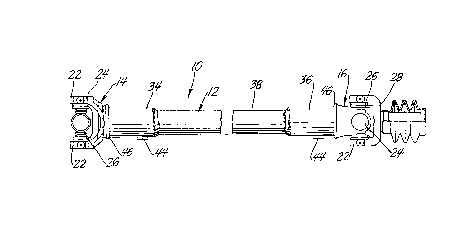
Fi;gure 1 is a longitudinal fragmentary front elevation view of a
propeller shaft assembly constructed in accordance with a presently preferred
embodiment of the invention;
Figure 2 is an enlarged fr~ nt~ry exploded view ofthe prop shaft
components of Figure 1 with the shaft in a pre-enlarged, pre-assembled condition;
and
Fig,ure 3 is an enlarged fragmentary longitudinal view, sho~vn partly
in section, of an end of the prop shaft assembly.
Detailed Descripti~n
F~eferring now to Figure 1, an automotive propeller shaft assembly
constructed in accordance with a presently preferred embodiment of the invention is
20 indicated generally by the reference numeral 10 and comprises an elongate drive
shaft 12 having yokes 14, 16 attached to its opposite ends.
The yokes 14, 16 are forged components, each having a cormecting
collar or shank 18 at one end presenting an outer mating surface 20 machined to a
predetermined diameter Dy . Laterally spaced ears 22 are formed at the opposite
25 end of the yokes 14, 16. The ears 22 are forrned with aligned cross holes 24 for
joumaling, in the usual manner, a spider 26 carried by another yoke 28 to provide a
Cardan-type universal joint at each end ofthe shaft 12.
The shai~ 12 comprises a longitudinally extending length of
cylindrical metal tubing material having opposite open ends 30, 32 thereof.
30 Initially, the tubular shaft 12 is of uniforrn small diameter along its length so as to
be undersized ~vith respect to the yokes 14, 16 that is attached to. The shaft 12 has
an initial outer diameter Do that is relatively smaller than that of the diameter Dy of

CA 02242l54 l998-07-03
~ /I P-325 4
the yoke shanks 18. The small outer diameter size of the tube 12 is selected to
facilitate linear routing of the shaft 12 in applications where space is limited, such
as, for example, in automotive front axle applications for coupling a vehicle's
transfer case to the front axle drive components.
In the example illustrated, the shaft has an initial outer diameter Do
of about 44.5 mm with a unifomm minimum wall thickness of about 2.4 mm and an
overall length dimension of about 679-740 mm. While specific dimensions and
ranges are given above for puIposes of illustration, those skilled in the art will
appreciate that other dimensions are possible and contemplated by the invention
1O based on the paIticular space limitations and length requirements for the particular
application.
The tubular shaft 12 has an initial inner diameter D~ that is govemed
in part by the initial outer diameter Do and the wall thickness of the tu~e but, in any
event is smaller in diameter than that of the outer diameter Dy of the yoke collars
15 18.
In accordance with the invention, opposite end sections 34, 36 of the
shaft 12 are enlarged to an expanded inner diameter De of sufficient size to provide
a press fit connection ~ith the collar 18 of the yokes 14, 16. In example illustrated,
the shaft 12 has an expanded inner diameter D~ in the range of about 49.2 to 49.33
2 0 rrlm, which corresponds in size with the diameter Dy of the yoke collars 18. The
small diameter midsection 38 of the shaft is unaffected by the enlargement of the
end sections 3~1, 36 and as such retains the original diameter and wall thickness
dimensions.
The enlargement of the end sections 34, 36 of the shaft 12 may be
25 carred out by a mechanical folming or flaring operation in which the shaft 12 is
clamped in a fixture (not shown) and an enlarged forming mandrel (not show-n)
extended into each of the open ends 30, 32 to stretch the tubing 12 in the vicinity of
the end sections 34, 36 to the enlarged inner diameter D~. The enlargement of the
end sections 34, 36 produces a corresponding reduction in their wall thickness by
30 aboutO.3mm.
As illustrated ~est in Figure 3, the length of the enlarged end
sections 34, 36 is relatively greater than that of the length of the yoke shanks 18.

CA 022421=,4 1998-07-03
AAM P-32j j
The extended length provides a region 42 inward of the yokes 14, 16 for eng~gingand supporting the shaft 12 during insertion of the collars 18 into the ends of the
shaft 12. The region 42 furtherprovides a location for eng~ging and supporting the
shaft 12 by a standard large diameter balancing fixture (not shown) and for
5 att~hing one or more standard large diameter balance weights 44 along each of the
end sections 34, 36.
After the enlarged end sections 34, 36 have been formed, the yokes
14, 16 are attached by press fitting the shanks 18 of the yokes into the open ends 30,
32 of the end sections 34, 36 until the end of the shaft 12 confront abutting
10 shoulders 14a, 16a of the yokes 14, 16, respectively. The yokes 14, 16 are then
fixed permanently to the shaft 12 by weldments 46 in the usual manner.
The balance weights 44 are selected and secured ~ dl~ly by
welding in the al)~lu~liate locations on the end sections 34, 36 to correct any
imbalance of the assembly 10. The extended length of the end sections 34, 36
enables the weights 44 to be attached at a location longitudinally spaced from the
insert shanks 18 of the yokes 14, 16 so as not to impair the integrity of the yoke-to-
shaft weldments 46.
The disclosed embodiment is representative of a presently preferred
fûrm of the invention, and is intended to be illustrative rather than definitive2 0 thereof. The invention is defined in the claims.

Representative Drawing
A single figure which represents the drawing illustrating the invention.
Administrative Status

2024-08-01:As part of the Next Generation Patents (NGP) transition, the Canadian Patents Database (CPD) now contains a more detailed Event History, which replicates the Event Log of our new back-office solution.

Please note that "Inactive:" events refers to events no longer in use in our new back-office solution.

For a clearer understanding of the status of the application/patent presented on this page, the site Disclaimer , as well as the definitions for Patent , Event History , Maintenance Fee  and Payment History  should be consulted.

Event History

Description Date
Inactive: IPC from MCD 2006-03-12
Application Not Reinstated by Deadline 2002-07-03
Time Limit for Reversal Expired 2002-07-03
Deemed Abandoned - Failure to Respond to Maintenance Fee Notice 2001-07-03
Application Published (Open to Public Inspection) 1999-01-07
Classification Modified 1998-10-14
Inactive: First IPC assigned 1998-10-14
Inactive: IPC assigned 1998-10-14
Filing Requirements Determined Compliant 1998-09-15
Inactive: Filing certificate - No RFE (English) 1998-09-15
Application Received - Regular National 1998-09-09

Abandonment History

Abandonment Date Reason Reinstatement Date
2001-07-03

Maintenance Fee

The last payment was received on 2000-06-21

Note : If the full payment has not been received on or before the date indicated, a further fee may be required which may be one of the following

  • the reinstatement fee;
  • the late payment fee; or
  • additional fee to reverse deemed expiry.

Patent fees are adjusted on the 1st of January every year. The amounts above are the current amounts if received by December 31 of the current year.
Please refer to the CIPO Patent Fees web page to see all current fee amounts.

Fee History

Fee Type Anniversary Year Due Date Paid Date
Application fee - standard 1998-07-03
Registration of a document 1998-07-03
MF (application, 2nd anniv.) - standard 02 2000-07-04 2000-06-21
Owners on Record

Note: Records showing the ownership history in alphabetical order.

Current Owners on Record
AMERICAN AXLE & MANUFACTURING INC.
Past Owners on Record
MARK S. BARRETT
THOMAS J. OLDENBURG
Past Owners that do not appear in the "Owners on Record" listing will appear in other documentation within the application.
Documents

To view selected files, please enter reCAPTCHA code :


To view images, click a link in the Document Description column. To download the documents, select one or more checkboxes in the first column and then click the "Download Selected in PDF format (Zip Archive)" or the "Download Selected as Single PDF" button.

List of published and non-published patent-specific documents on the CPD .

If you have any difficulty accessing content, you can call the Client Service Centre at 1-866-997-1936 or send them an e-mail at CIPO Client Service Centre.


Document
Description 
Date
(yyyy-mm-dd) 
Number of pages   Size of Image (KB) 
Description 1998-07-02 5 221
Claims 1998-07-02 2 73
Drawings 1998-07-02 1 29
Abstract 1998-07-02 1 17
Representative drawing 1999-01-25 1 6
Courtesy - Certificate of registration (related document(s)) 1998-09-14 1 140
Filing Certificate (English) 1998-09-14 1 174
Reminder of maintenance fee due 2000-03-05 1 113
Courtesy - Abandonment Letter (Maintenance Fee) 2001-07-30 1 182