Language selection

Search

Patent 2242548 Summary

Third-party information liability

Some of the information on this Web page has been provided by external sources. The Government of Canada is not responsible for the accuracy, reliability or currency of the information supplied by external sources. Users wishing to rely upon this information should consult directly with the source of the information. Content provided by external sources is not subject to official languages, privacy and accessibility requirements.

Claims and Abstract availability

Any discrepancies in the text and image of the Claims and Abstract are due to differing posting times. Text of the Claims and Abstract are posted:

  • At the time the application is open to public inspection;
  • At the time of issue of the patent (grant).
(12) Patent Application: (11) CA 2242548
(54) English Title: CYLINDRICAL CONTACT TUBE
(54) French Title: TUBE DE CONTACT CYLINDRIQUE
Status: Deemed Abandoned and Beyond the Period of Reinstatement - Pending Response to Notice of Disregarded Communication
Bibliographic Data
(51) International Patent Classification (IPC):
  • H01R 4/60 (2006.01)
  • B60R 16/02 (2006.01)
  • H01R 13/115 (2006.01)
(72) Inventors :
  • MAY, GUNTRAM (Germany)
  • ODORFER, FRANK (Germany)
(73) Owners :
  • FRAMATOME CONNECTORS INTERNATIONAL
(71) Applicants :
  • FRAMATOME CONNECTORS INTERNATIONAL (France)
(74) Agent: LAVERY, DE BILLY, LLP
(74) Associate agent:
(45) Issued:
(22) Filed Date: 1998-07-07
(41) Open to Public Inspection: 1999-02-08
Availability of licence: N/A
Dedicated to the Public: N/A
(25) Language of filing: English

Patent Cooperation Treaty (PCT): No

(30) Application Priority Data:
Application No. Country/Territory Date
DE 197 34 524 (Germany) 1997-08-08

Abstracts

English Abstract


The present invention relates to a cylindrical
contact tube (1) having a contact part (2) and a connecting
part (3). The contact part (2) has a cylindrical
lateral surface (4) with at least one contact spring (5)
which is punched out of the lateral surface (4) and
orientated essentially parallel to the plug-in direction,
the contact spring additionally being coined.


French Abstract

La présente invention porte sur un tube de contact cylindrique (1) ayant une partie de contact (2) et une partie de connexion (3). La partie de contact (2) a une surface latérale cylindrique (4) avec au moins une lame de contact (5) découpée dans la surface latérale (4) et est orientée essentiellement parallèle au sens d'enfichage, la lame de contac étant en outre estampée.

Claims

Note: Claims are shown in the official language in which they were submitted.

- 4 -
claims
1. Cylindrical contact tube (1) having a contact
part (2) and a connecting part (3), characterized in that
the contact part (2) has a cylindrical lateral surface
(4) with at least one contact spring (5) which is punched
out of the lateral surface (4) and orientated essentially
parallel to the plug-in direction, the contact spring
additionally being coined.
2. Contact tube according to Claim 1, characterized
in that the width of the contact spring (5) decreases
from the base (6) of the spring to the free end (7).
3. Contact tube according to Claim 1 or Claim 2,
characterized in that two facing contact springs are
provided which have free ends (7) orientated towards the
tube inlet.
4. Contact tube according to one of the preceding
claims, characterized in that in its base region (6) the
contact spring (5) has a coined part (8) in the form of
a conical frustum segment which stiffens the spring (5)
in this region.
5. Contact tube according to one of the preceding
claims, characterized in that the free end (7) of the
contact spring (5) is coined in the shape of a spoon with
the convex side radially outwards.
6. Method for producing a contact tube according to
one of the preceding claims, characterized in that the
contact springs are coined with a coining punch between
punching out the sheet metal and rolling the
semi-finished products to form the contact tube.

Description

Note: Descriptions are shown in the official language in which they were submitted.


CA 02242~48 1998-07-07
.
,--
FRAMATOME CONNECTORS
Daut + Riotz ~mhH
D-90411 Nuremborg
Cylindrical contact tube
The present invention relates to a cylindrical
contact tube according to the preamble of Patent Claim 1.
Such contact tubes are u~ed, inter alia, in the automo-
bile industry, where, in addition to a certain robustness
of the plug-in connection, importance attaches to easy
insertion of the mating connector and to a firm contact
pressure of the contact elements against one another.
Contact tubes are ~nown which are p~nche~ out of
a metal ~heet, the cylindrical tube body being produced
by rolling and/or ~-n~ng the p~nche~ metal sheet, and an
elastic behaviour being achieved by leaving a gap paral-
lel to the plug-in axis between the facing p~n~hs~ edges,
and keeping the inside diameter of the cylindrical tube
slightly smaller with respect to the diameter of the plug
part to be plugged in, whilst producing holding forces
upon plugging in because of the required wi~n i ng of the
cylindrical latoral surface. This type of plug sleeve
does not permit an effectively reproducible contact
resistance to be produced, since the surface where the
plug parts are seated on one another can vary very
considerably from one plug to another.
An improvement i8 achieved in the case of a
cylindrical tube by pl~nc~;ng out of the cylindrical
lateral surface spring tongue6 which are bent into the
tube interior in order thereby to produce defined contact
surfaces. This is already a great improvement with regard
to the reproducibility of the contact situation. With
regard to the elasticity of the~e contact springs, and to
the contact pressure, such contact tubes are still not
ideal, however, since although long contact springs
permit excellent elastic properties and large spring
excursions, they permit only a slight contact pressure.
Short contact springs make it difficult to insert the

CA 02242~48 1998-07-07
-- 2
mating connector, but deliver an acceptable contact
pressure.
It i~ the ob;ect of the present invention to
improve a cylindrical contact tube 80 as to ensure a
large contact pressure between the contact surfaces in
conjunction with good elastic properties which simplify
the insertion of the mating connector.
This object is achieved in accordance with the
claim. The subclaims characterize preferred embodiments
of the invention.
The invention is explained in more detail below
with the aid of the description of an exemplary embodi-
ment and with reference to th- drawing, in which:
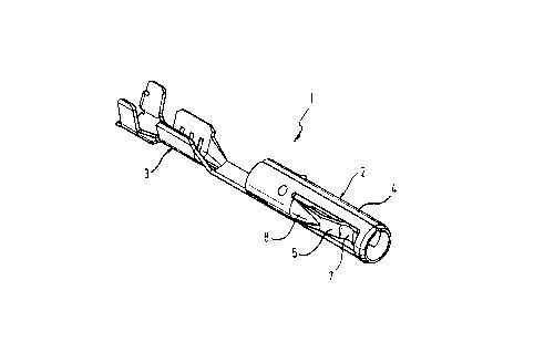
Figure 1 shows a per~peetive ~iew of a cylindrical
contact tube according to the invention;
Figure 2 shows a sectional plan view of a semifinished
contact tube, and
Figure 3 show~ a detailed sectional view of a contact
spring.
The contact tube 1 shown in Figure 1 ha~ a
contact part 2 and a connecting part 3. The contact part
2 has a cylindrical lateral surface 4, which is formed by
rolling a p~nche~ metal sheet. Visible on the top side of
the cylindrical lateral surface is the joining edge where
the facing sides of the p~nch~ metal sheet abut. To the
right and left, contact springs 5 are punched out of the
cylindrical lateral surface parallel to the plug-in axis.
The shape and working of this contact spring will
be examined in more detail below.
Figure 2 shows the p~che~ metal sheet of the
contact tube 1 a a semi-finished product in one plane.
Vi~ible on the right is the plug part with the cylindri-
cal lateral surface 4, and the punched-out contact
springs 5. The free ends of the contact springs extend in
the direction opposite to the plugging inlet of the
contact tube. Contact springs widen towards their rear
end, at which they are connected to the cylindrical
lateral surface. The rear region of the contact spring,
termed the base region 6 below, i~ coined with a coining

CA 02242~48 1998-07-07
punch in an operation preceding the rolling together of
the cylindrical lateral surface 80 a~ to produce a bulge
in the form of a conical frustum segment, as may be seen
from Figure 1. The coined part 8 increases the stiffnes~
of the contact spring in lts base region 6. As is best
seen from Figure 3, adjolning this is an essQntially
straight spring part which carries the spring tip which
i8, in turn, coined in the shape of a spoon. The convex
surface of the spring contact tip points radially out-
wards in this case. The result is to ensure a welldefined seating point of the contact spring on the mating
connector.
As may be seen from Figure 1, the contact spring
tip 7 can also have only a curvature in the shape of a
cylindrical segment, the generators of the cylindrical
lateral surface ext~nAing perpendicular to the plug-in
direction of the contact tube.
The contact tube according to the invention
combines the advantages of large contact spring lengths,
specifically that the contact spring tips can cover a
large spring excursion and have an elastic behaviour,
with a high contact pressure because the coining achieves
a higher contact pressure of the contact spring. The
contact tube shown in the figures has two facing contact
springs. This is only one possibility of the arrangement
of contact springs on a cylindrical contact tube. It is
likewise conceivable to arrange only one or three or four
contact springs, it al~o being possible to conceive of a
plurality of contact springs at a different height with
reference to the plug-in depth of the contact tube.
Furthermore, depen~;n~ on the application, other
coinings of the spring contact are conceivable in order
to influence the ben~; ng behaviour of the contact ~pring
and also to influence the contact surface on the spring
tip exactly as desired.

Representative Drawing
A single figure which represents the drawing illustrating the invention.
Administrative Status

2024-08-01:As part of the Next Generation Patents (NGP) transition, the Canadian Patents Database (CPD) now contains a more detailed Event History, which replicates the Event Log of our new back-office solution.

Please note that "Inactive:" events refers to events no longer in use in our new back-office solution.

For a clearer understanding of the status of the application/patent presented on this page, the site Disclaimer , as well as the definitions for Patent , Event History , Maintenance Fee  and Payment History  should be consulted.

Event History

Description Date
Application Not Reinstated by Deadline 2003-07-07
Time Limit for Reversal Expired 2003-07-07
Deemed Abandoned - Failure to Respond to Maintenance Fee Notice 2002-07-08
Application Published (Open to Public Inspection) 1999-02-08
Inactive: Courtesy letter - Evidence 1998-11-13
Inactive: First IPC assigned 1998-10-23
Inactive: IPC assigned 1998-10-23
Inactive: First IPC assigned 1998-10-23
Inactive: IPC assigned 1998-10-23
Inactive: IPC removed 1998-10-23
Inactive: IPC assigned 1998-10-23
Classification Modified 1998-10-23
Inactive: IPC assigned 1998-10-22
Inactive: Single transfer 1998-09-28
Inactive: Courtesy letter - Evidence 1998-09-22
Inactive: Filing certificate - No RFE (English) 1998-09-16
Filing Requirements Determined Compliant 1998-09-16
Application Received - Regular National 1998-09-14

Abandonment History

Abandonment Date Reason Reinstatement Date
2002-07-08

Maintenance Fee

The last payment was received on 2001-06-21

Note : If the full payment has not been received on or before the date indicated, a further fee may be required which may be one of the following

  • the reinstatement fee;
  • the late payment fee; or
  • additional fee to reverse deemed expiry.

Please refer to the CIPO Patent Fees web page to see all current fee amounts.

Fee History

Fee Type Anniversary Year Due Date Paid Date
Application fee - standard 1998-07-07
Registration of a document 1998-09-28
MF (application, 2nd anniv.) - standard 02 2000-07-07 2000-05-29
MF (application, 3rd anniv.) - standard 03 2001-07-09 2001-06-21
Owners on Record

Note: Records showing the ownership history in alphabetical order.

Current Owners on Record
FRAMATOME CONNECTORS INTERNATIONAL
Past Owners on Record
FRANK ODORFER
GUNTRAM MAY
Past Owners that do not appear in the "Owners on Record" listing will appear in other documentation within the application.
Documents

To view selected files, please enter reCAPTCHA code :


To view images, click a link in the Document Description column. To download the documents, select one or more checkboxes in the first column and then click the "Download Selected in PDF format (Zip Archive)" or the "Download Selected as Single PDF" button.

List of published and non-published patent-specific documents on the CPD .

If you have any difficulty accessing content, you can call the Client Service Centre at 1-866-997-1936 or send them an e-mail at CIPO Client Service Centre.


Document
Description 
Date
(yyyy-mm-dd) 
Number of pages   Size of Image (KB) 
Representative drawing 1999-03-01 1 6
Abstract 1998-07-07 1 12
Claims 1998-07-07 1 36
Description 1998-07-07 3 143
Drawings 1998-07-07 2 25
Cover Page 1999-03-01 1 33
Filing Certificate (English) 1998-09-16 1 174
Courtesy - Certificate of registration (related document(s)) 1998-12-02 1 114
Reminder of maintenance fee due 2000-03-08 1 111
Courtesy - Abandonment Letter (Maintenance Fee) 2002-08-05 1 183
Reminder - Request for Examination 2003-03-10 1 120
Correspondence 1998-09-22 1 36
Correspondence 1998-11-13 1 12
Fees 2001-06-21 1 39
Fees 2000-05-29 1 39