Some of the information on this Web page has been provided by external sources. The Government of Canada is not responsible for the accuracy, reliability or currency of the information supplied by external sources. Users wishing to rely upon this information should consult directly with the source of the information. Content provided by external sources is not subject to official languages, privacy and accessibility requirements.
Any discrepancies in the text and image of the Claims and Abstract are due to differing posting times. Text of the Claims and Abstract are posted:
| (12) Patent: | (11) CA 2242612 |
|---|---|
| (54) English Title: | SLOTTED COMPONENT MANUFACTURE |
| (54) French Title: | FABRICATION D'UN COMPOSANT RAINURE |
| Status: | Expired and beyond the Period of Reversal |
| (51) International Patent Classification (IPC): |
|
|---|---|
| (72) Inventors : |
|
| (73) Owners : |
|
| (71) Applicants : |
|
| (74) Agent: | SMART & BIGGAR LP |
| (74) Associate agent: | |
| (45) Issued: | 2005-08-16 |
| (86) PCT Filing Date: | 1997-09-23 |
| (87) Open to Public Inspection: | 1998-04-02 |
| Examination requested: | 2001-11-06 |
| Availability of licence: | N/A |
| Dedicated to the Public: | N/A |
| (25) Language of filing: | English |
| Patent Cooperation Treaty (PCT): | Yes |
|---|---|
| (86) PCT Filing Number: | PCT/AU1997/000628 |
| (87) International Publication Number: | WO 1998013163 |
| (85) National Entry: | 1998-07-09 |
| (30) Application Priority Data: | ||||||
|---|---|---|---|---|---|---|
|
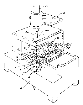
This invention relates to a method for manufacturing a
plurality of longitudinally extending slots in the bore of a component
(1). One example of such a component is the sleeve element of
an automotive power steering rotary valve. More particularly the
invention is directed towards a method of minimising burring of
the slot edges of the sleeve component. The method comprises
the steps of gripping said component (1) in a gripping means (2)
of a workholding device, performing a first cutting operation (5)
in which said slot is cut in said bore by a series of progressively
deeper cutting strokes of a cutting tool (5), further machining (30)
said bore of said component, said machining of said bore being
carried out whilst the component remains gripped in said
gripping means, characterised in that whilst said component remains
gripped in said gripping means said slot undergoes a second
cutting operation (5) similar to the first operation.
La présente invention concerne un procédé de réalisation d'une pluralité de rainures longitudinales dans l'alésage d'un composant (1). Ce composant peut notamment être l'élément de chemisage de la soupape à piston d'une direction assistée d'automobile. En l'occurrence, l'invention vise à ramener à un minimum le phénomène d'épaississement des bords affectant les bords de rainures de l'élément de chemisage. Le procédé consiste d'abord à immobiliser le composant (1) dans l'organe d'immobilisation (2) d'un dispositif porte-pièce. Le procédé consiste ensuite à exécuter une première opération de coupe (5) au cours de laquelle l'alésage est entaillé en une succession de passes de coupe de l'outil de coupe (5) de plus en plus profondes. Le procédé consiste enfin à poursuivre l'usinage (30) de l'alésage du composant. L'usinage de l'alésage s'effectue alors que le composant est immobilisé dans l'organe d'immobilisation. L'une des caractéristiques est que pendant que le composant est immobilisé dans l'organe d'immobilisation, la rainure subit une seconde opération de coupe (5) similaire à la première opération.
Note: Claims are shown in the official language in which they were submitted.
Note: Descriptions are shown in the official language in which they were submitted.
2024-08-01:As part of the Next Generation Patents (NGP) transition, the Canadian Patents Database (CPD) now contains a more detailed Event History, which replicates the Event Log of our new back-office solution.
Please note that "Inactive:" events refers to events no longer in use in our new back-office solution.
For a clearer understanding of the status of the application/patent presented on this page, the site Disclaimer , as well as the definitions for Patent , Event History , Maintenance Fee and Payment History should be consulted.
| Description | Date |
|---|---|
| Time Limit for Reversal Expired | 2009-09-23 |
| Letter Sent | 2008-09-23 |
| Grant by Issuance | 2005-08-16 |
| Inactive: Cover page published | 2005-08-15 |
| Inactive: Final fee received | 2005-06-07 |
| Pre-grant | 2005-06-07 |
| Letter Sent | 2004-12-10 |
| Notice of Allowance is Issued | 2004-12-10 |
| Notice of Allowance is Issued | 2004-12-10 |
| Inactive: Approved for allowance (AFA) | 2004-11-29 |
| Amendment Received - Voluntary Amendment | 2004-08-26 |
| Inactive: S.29 Rules - Examiner requisition | 2004-02-26 |
| Inactive: S.30(2) Rules - Examiner requisition | 2004-02-26 |
| Amendment Received - Voluntary Amendment | 2002-05-01 |
| Letter Sent | 2001-12-06 |
| Request for Examination Requirements Determined Compliant | 2001-11-06 |
| Request for Examination Received | 2001-11-06 |
| Amendment Received - Voluntary Amendment | 2001-11-06 |
| All Requirements for Examination Determined Compliant | 2001-11-06 |
| Inactive: Notice - National entry - No RFE | 1999-03-01 |
| Inactive: Single transfer | 1999-02-25 |
| Inactive: Filing certificate correction | 1999-01-18 |
| Filing Requirements Determined Compliant | 1999-01-18 |
| Inactive: IPC assigned | 1998-10-09 |
| Inactive: First IPC assigned | 1998-10-09 |
| Classification Modified | 1998-10-09 |
| Inactive: IPC assigned | 1998-10-09 |
| Inactive: Courtesy letter - Evidence | 1998-09-22 |
| Inactive: Notice - National entry - No RFE | 1998-09-17 |
| Application Received - PCT | 1998-09-14 |
| Application Published (Open to Public Inspection) | 1998-04-02 |
There is no abandonment history.
The last payment was received on 2004-08-31
Note : If the full payment has not been received on or before the date indicated, a further fee may be required which may be one of the following
Please refer to the CIPO Patent Fees web page to see all current fee amounts.
| Fee Type | Anniversary Year | Due Date | Paid Date |
|---|---|---|---|
| Basic national fee - standard | 1998-07-09 | ||
| Registration of a document | 1999-02-25 | ||
| MF (application, 2nd anniv.) - standard | 02 | 1999-09-23 | 1999-09-01 |
| MF (application, 3rd anniv.) - standard | 03 | 2000-09-25 | 2000-09-05 |
| MF (application, 4th anniv.) - standard | 04 | 2001-09-24 | 2001-08-31 |
| Request for examination - standard | 2001-11-06 | ||
| MF (application, 5th anniv.) - standard | 05 | 2002-09-23 | 2002-09-09 |
| MF (application, 6th anniv.) - standard | 06 | 2003-09-23 | 2003-09-17 |
| MF (application, 7th anniv.) - standard | 07 | 2004-09-23 | 2004-08-31 |
| Final fee - standard | 2005-06-07 | ||
| MF (patent, 8th anniv.) - standard | 2005-09-23 | 2005-09-13 | |
| MF (patent, 9th anniv.) - standard | 2006-09-25 | 2006-06-15 | |
| MF (patent, 10th anniv.) - standard | 2007-09-24 | 2007-06-20 |
Note: Records showing the ownership history in alphabetical order.
| Current Owners on Record |
|---|
| BISHOP STEERING PTY. LIMITED |
| Past Owners on Record |
|---|
| KLAUS JUERGEN ROESKE |

