Note: Descriptions are shown in the official language in which they were submitted.
> r. ' , r CA 02242707 1998-07-09
v T
1. ~CCUS-038
Field of the Invention
This invention relates to optical fiber cables and,
more particularly, to multi-purpose optical fiber cables
comprising a central tube and a plurality of outer tubes, each of
w~iich contain optical fibers, and a supporting system to protect
the optical fibers from forces, such as installation forces and
thermally induced expansion and contraction of the tubes in which
they are contained.
Bac round of the Invention
Optical fibers are relatively fragile and must be
protected during manufacture and installation. A variety of
protective measures are therefore provided in cables containing
optical fibers. The optical fiber or fibers are typically
enclosed in a plastic buffer tube having a bore of a cross-
sectional area larger than the cross-sectional area of the fiber
or fibers within it. This is referred to as a ~~loose~~
configuration. The material of the tube typically has a
relatively high temperature coefficient of expansion and a
relatively low tensile strength. Frequently, the axial length of
the tube is shorter than the linear length of the fibers or
ribbons. The tube can move or be flexed a certain degree by
external forces or by thermal expansion and contraction, without
bending the optical fiber ribbon.
To further resist thermal expansion and contraction,
strength members of metal wires, high strength non-metallic rods
or fibers, such as glass rods or fibers or aramid in a matrix of
resin, can be provided adjacent the tube or tubes containing the
optical fibers. See, for example, U.S. Patent Nos. 5,509,097 and
5,229,851, assigned to the assignee of the present invention.
Strength members have been provided in the outer jacket
or sheath to resist pulling, such as pulling which occurs during
CA 02242707 1998-07-09
1 installation of a cable. Additional layers of materials, such as
armoring for crushing and rodent protection, can also be
provided. For moisture protection, the tube is typically filled
with a water blocking compound which permits the fibers or
ribbons to move within the buffer tubes. The water blocking
compound may be a gel or grease-like, and non-hygroscopic and/or
thixotropic.
Optical fiber cables are available in a variety of
configurations. For example, optical fiber cables are available
comprising one or more optical fibers, an optical fiber ribbon or
an optical fiber bundle loosely contained within a central tube.
Optical fiber ribbons are typically preferred where high fiber
counts are required, such as feeder and distribution segments of
an optical fiber network. They are also used to connect
locations separated by long distances, referred to as long haul
applications, such as connecting central telephone stations to
Local networks. Such cables could also be used in cable TV
networks or as data links between computers. In U.S. Patent No.
5,509,097, described above, the central tube loosely contains an
optical fiber ribbon. .
Optical fiber cables are also available comprising a
plurality of tubes, each containing a plurality of optical fibers
in a loose configuration and disposed around a central strength
member to resist thermal expansion and contraction. Further
strength members can also be provided in an outer protective
jacket. Such cables are typically used where the ability to
splice to different local points is required. For higher fiber
count applications, optical fiber ribbons can be disposed in each
of the tubes. See, for example, U.S. Patent No. 5,229,851.
Optical fiber cables have been proposed which include
both a central tube containing optical fibers for long haul
applications and a plurality of outer tubes containing optical
fibers for shorter distance connections. U.S. Patent No.
2
- ' , : CA 02242707 1998-07-09
1 4,822,132, to Oestreich, for example, discloses an optical
communications cable for use in local cable networks comprising
an inner central tube surrounded by a plurality of smaller tubes,
each containing fewer optical fibers than the central tube. The
outer tubes are stranded about the central tube in an alternating
twist or reverse oscillating lay configuration. The outer tubes
are accessible for splicing and branching while the central tube
can continue through branching locations to cable terminals. No
strength member system is provided to resist longitudinal forces,
such as the forces due to installation and thermal expansion and
contraction.
U.S. Patent No. 4,230,395 to Dean et al., discloses an
optical fiber cable comprising a plurality of optical fibers
loosely contained within a plurality of tubes, surrounded by a
sheath. A central tube containing optical fibers can also be
provided, and is surrounded by the plurality of non-stranded
tubes. Reinforcing members extending parallel to the cable axis
are embedded in the sheath, in the tube walls, or can be between
the plurality of tubes and the sheath but spaced from the central
tube. Thus, the reinforcing members do not resist longitudinal
expansion and contraction of the central tube.
U.S. Patent No. 4,078,853 to Kempf et al., discloses an
optical fiber cable comprising a plurality of tubes, each loosely
containing an optical fiber ribbon, helically stranded around a
central tube, also containing an optical fiber ribbon. An outer
jacket reinforced with strength members surrounds the tubes.
However, none of the references cited hereinbefore
suggests that when outer tubes containing optical fibers are
disposed around a central tube containing optical fibers,
structural strength members should be placed between the outer
tubes and in contact with the central tube or that the outer
CA 02242707 1999-10-19
tubes with the structural strength members therebetween should
be wound around the central tube. It is unexpected that such a
configuration would provide better protection for the optical
fibers contained within the outer tubes and the central tube
from thermal expansion and contraction, because the strength
members are not substantially rectilinear and parallel with the
cable axis, as in the prior art.
SZTMMARY OF THE INVENTION
In accordance with one aspect of the present
invention, there is provided an optical fiber cable comprising:
a central tube loosely containing at least one optical fiber; a
plurality of outer tubes, at least one of said outer tubes
containing at least one optical fiber, and at least two
structural strength members having a tensile modulus which is
high relative to the tensile modulus of said central tube and
having a temperature coefficient of expansion less than the
temperature coefficient of expansion of said central tube, said
outer tubes and said strength members being disposed around
said central tube in a reverse oscillating lay configuration
and with said strength members in contact with said central
tube, said structural strength members being spaced from each
other in the circumferential direction of said central tube and
intermediate pairs of said outer tubes, wherein said strength
members are coupled to said central tube and have a tensile
strength and resistance to compression sufficient to protect
the optical fibers in the central tube with respect to
contraction or expansion upon application of longitudinal
forces on the cable; and a sheath encircling said outer tubes
and said structural strength members.
A cord is preferably wound about the outer tubes and
structural members. The central tube preferably contains a
- 4 -
CA 02242707 1999-10-19
plurality of optical fiber ribbons each containing optical
fibers and the outer tubes preferably contain a plurality of
individual loose optical fibers, i.e., optical fibers which are
not bonded to each other, such as by way of encapsulation in a
plastic. However, the fibers can be tightly buffered within
the outer tubes. The structural members can comprise metallic
or dielectric materials. Longitudinal strength members can
also be embedded within the sheath. The optical fibers, both
the individual fibers and the fiber containing ribbons, can be
loosely contained within the central and outer tubes. One or
- 4a -
CA 02242707 1998-07-09
1 more of the outer tubes, but not all the outer tubes, can contain
a coaxial cable or copper pair instead of optical fibers.
De~criL2t~on of the Drawinos
Fig. 1 is a cross-sectional view of a combination
optical fiber cable 10 in accordance with one embodiment of the
present invention;
Fig. 2 is a perspective view of the combination cable
of Fig. 1, with its sheath and armoring partially removed;
Fig. 3 is a cross-sectional view of an outer tube
containing a twisted copper pair;
Fig. 4 is a cross-sectional view of an outer tube
containing a coaxial cable; and
Fig. 5 is a cross-sectional view of a modification of
the embodiment shown in Fig. 1 in which the water blocking
material outside the tubes is replaced by a dry water swellable
yarn or tape.
D~sc~-~nt~on of the Invention
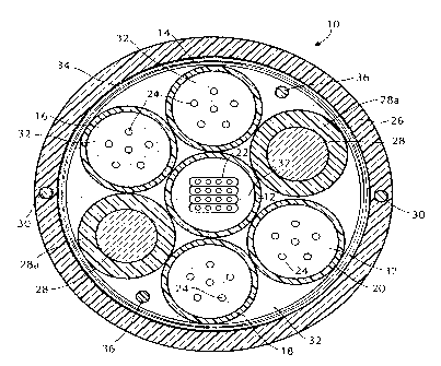
Fig. 1 is a cross-sectional view of a combination
optical fiber cable 10 in accordance with one embodiment of the
present invention, comprising a central tube-12 containing at
least one optical fiber and a plurality of outer tubes 14, 16, 18
and 20 disposed around the central tube 12, each of which also
contains at least one optical fiber. The tubes 12, 14, 16, 18
and 20 can contain a single optical fiber, a plurality of
separate optical fibers, an optical fiber ribbon, or an optical
fiber bundle . Preferablv. as slo~wn ;" F; ~ , a ,-,~ "r~, , ~"
optical fiber ribbons 22 are contained within the central tube
12, and a plurality of individual optical fibers 24 not bonded to
each other, are contained within four outer tubes 14, 16, 18 and
20. Six optical fibers 24 are shown in each of the outer tubes
14, 16, 18 and 20 for illustrative purposes only, but the number
of fibers can be more or less. The tubes 12, 14, 16, 18 and 20
have inner diameters selected so that the cross-sectional area of
5
CA 02242707 1998-07-09
3, the bores of the tubes are greater than the cross-sectional area
of the optical fiber, plurality of fibers, or ribbons contained
therein so that the optical fiber or fibers and ribbons are
loosely contained, therein. A sheath 26 surrounds the outer
tubes. The fibers and ribbons are of any known type, the ribbons
comprising a planar array of fibers encapsulated in a plastic.
Any or all of the outer tubes 14, 16, 18 and 20 can have inner
diameters such that the cross-sectioned area of the bores of the
tubes are essentially the same as the cross-sectional area of the
optical fiber, plurality of fibers, or ribbons contained therein,
as well. Such a configuration is referred to as tight buffered
ffibers.
At least two structural strength members 28 are
provided between the central tube 12 and the sheath 26, between
the outer tubes 14, 16, 18 and 20. The structural strength
members 28 can be made of any high tensile modulus material,
e.g., a non-metallic material, such as glass, epoxy rods,
graphite yarns or a metallic material, such as stainless steel or
carbon steel coated with copper or zinc to prevent corrosion.
The coefficient of thermal expansion of the strength members 28
is less than that of the central tube 12 and outer tubes 14, 16,
18 and 20 and the tensile modulus of the strength members is
higher than the tensile modulus of such tubes. The structural
strength members 28 are shown covered by an optional covering
28a, such as polyethylene, for example, but the covering 28a can
be omitted, particularly if the strength member is non-metallic.
The diameter of the strength member 28 is preferably no greater
than that required to provide the desired protection. When the
strength member 28 is metallic, the diameter of the strength
member 28 is typically less than the diameter of the outer tubes
16. The thickness of the covering 28a is preferably about equal
to the difference between the diameter of the strength member 28
and the diameter of the outer tube 16.
6
CA 02242707 1998-07-09
. The central tube 12 preferably comprises a plastic
material, such as high density polyethylene (~~I~PE"). The outer
tubes 14, 16, 18 and 20 also preferably comprise a plastic
material, such as polybutylene terephtalate ( "PBT'~ ) or I-APE .
Other suitable plastic materials for the inner and outer tubes
include polypropylene, polyvinylchloride and polymethylpentene.
The plastic materials for the central and outer tubes preferably
have a Young~s Modulus in the range of from 20,000 to 500,000
psi. The central and outer tubes can also be metallic or
composite materials, such as an epoxy mixed with glass fibers.
The sheath 26, which is also, preferably, a plastic material, may
be medium density polyethylene (t'MDPE"), for example.
Preferably, two diametrically opposed longitudinal
strength members 30 extending substantially parallel to the axis
of the cable 10 are embedded in the sheath 26. The longitudinal
strength members can be steel, for example, as is known in the
art. The longitudinal strength members 30 in the sheath 26
protect the optical fibers from longitudinal stresses such as
pulling during installation. If the cable 10 is intended to be
used in applications which do not require pulling during
installation, such as cables to be installed by the "blown-in~~
technique, strength members in the sheath may not be necessary.
The strength members 30 also allow bending of the cable
perpendicular to the plane containing the two strength members
30.
Preferably, a water blocking material 32 is provided
within the central tube 12, within the outer tubes 14, 16, 18 and
20, and in the open spaces between the central tube 12, outer
tubes 14, 16, 18 and 20 and the sheath 26. The water blocking
material 32 within the outer tubes 14, 16, 18 and 20 can be a
thixotropic grease or gel, preferably with a viscosity at 20
seconds-1 in the range of from 8,000 to 25,000 cps. at 25°C.
Preferably, the water blocking material in the open spaces
7
CA 02242707 2002-02-20
77909-38
between the sheath 25 and the central tube 12, outside the
outer tubes 14, 16, 18 and 20, is a thixotropic grease or
gel having viscosity in the range of from 10 to 500 cps. at
125°C., in accordance with ASTM D-2699. The water blocking
material preferred within the buffer tubes 14, 15, 18 and
20, discussed above, can be used in the open spaces outside
of the tubes, as well. The material can contain small
particles, preferably of a size less than about 500 microns,
of a knc>wn water swellable material, such as sodium
acrylate~, to assist: in preventing moisture from affecting
the optical fibers. In addition, or in the alternative,
compounds for absorbing gas, such as hydrogen, may also be
provided for assisting in protecting the optical fibers from
delet=eri.ous gases .
Alternatively, and in place of a water blocking
material. 32, a known type of water swellable yarn 67 can be
stranded with the outer tubes 14, 16, 18 and 20 as shown in
Fig. 5. Instead oi: the yarn 67, or in addition thereto, a
known type of water_ swellable tape 68 can be wound around
the outer tubes.
A layer c>f corrugated steel armor 34 is optionally
prow=ided around the outer tubes 14, 16, 18 and 20, and the
tape 68, if present, adjacent to the inner surface of the
sheai~h 26, to provide additional protection against crushing
and rodents, for example. The armor 34 can be of the type
described in U.S. Fat. No. 5,509,097.
Preferably, one or more ripcords 36 extending
generally parallel to the axis of the cable 16 are also
provided adjacent the inner surface of the sheath 26 or the
inner surface of true corrugated steel armor 34, if provided,
to e<~se opening of the sheath 26, or the armor 34 and the
8
CA 02242707 2002-02-20
77909-38
sheath 26 when access to the tubes is required. Two
ripcord's 36 are shown in Figs. 1 and 15, although one or
more than two can be included. The ripcords may be aramid,
for example.
8a
CA 02242707 1998-07-09
1 , In accordance with the present invention, the outer
tubes 14, 16, 18 and 20 and strength members 28 are engaged with
the central tube 12, as shown in the perspective view of the
combination cable 10 of the present invention in Fig. 2. In
Fig. 2, the sheath 26 and the armor 34 are partially removed.
The outer tubes and the strength member 28 are preferably wound
in a reverse oscillating lay configuration. A cord 38 of
polyester, nylon, aramid or fiberglass, for example, is
preferably tied around the outer tubes 14, 16, 18 and 20 and
strength members 28, to more tightly couple the outer tubes and
strength members to each other and to the central tube 12. The
cord can be in the form of a monolithic fiber, a thread or a
yarn. The cord 38 applies radial inward forces to the structural
strength members 28 and the outer tubes 14, 16, 18 and 20,
maintaining the contact between the strength members, outer tubes
and the central tube 12, to resist contraction or expansion of
the tubes and buckling of the tubes caused by longitudinal forces
on the tubes. The cord 38 is preferably wound under tension, in
the range of from about 200 grams to about 2,000 grams, for
example. Preferably, the tension is in the range of from 600 to
1500 grams. The diameter of the cord is preferably less than
about 2 mm. Its tensile strength at break is at least about
6,000 psi. Instead of a cord 38, a tape, such as a commercially
available polyester type with a tensile strength of about 6,000
psi, may be used. The tape may have a thickness of about 0.020
nun to about 0.030 mm, and a width preferably less than about 1
inch, for example.
In the reverse oscillating lay configuration, the outer
tubes and the strength members are wound first in one direction
around the central tube 12, and then wound in the opposite
direction. Between the oppositely wound sections is a section
"S" wherein the outer tubes 14, 16, 18 and 20 are parallel to
each other and substantially parallel to the axis of the central
0
CA 02242707 1998-07-09
1 tube 12. This is the preferred section for carrying out splices
with the optical fiber in the outer tubes.
It has been found that winding the strength members 28
with the outer tubes 14, 16, 18 and 20 provides better coupling
between the strength members 28, the outer tubes 14, 16, 18 and
20 and the central tube 12, providing better resistance to
thermal expansion and contraction of the outer tubes and the
central tube. Binding the outer tubes and strength members to
the central tube through a cord 38 further strengthens the
coupling between the outer tubes, strength members and the
central tube, further improving the resistance of the outer tubes
and central tube to thermal expansion and contraction and to
buckling. The combination optical fiber cable of the present
invention can operate over a temperature range of from about
-40°C to about 70°C and preferably, over a temperature range of
about -50°C to about 90°C.
A twisted copper pair or a coaxial cable may be
substituted for one or more, but not all, tubes containing
optical fibers. Fig. 3 is a cross-sectional view of an outer
tube 50, which can replace one of the-tubes 14-18, containing a
twisted pair of electrically conductive copper wires 52, each of
which is surrounded by insulation 54. Fig. 4 is a cross-
sectional view of another outer tube 56, which can replace one of
the tubes 14-18, containing a coaxial cable 58. A typical
coaxial cable includes an outer insulation layer 60, an outer
conductor 62, an inner conductor 64 and insulation 66 between the
outer and inner conductors 62, 64, as is known in the art. While
water blocking material 32 can be included in the tubes 50 and
56, it can be omitted. The twisted copper pair 52 or coaxial
cable 58 need not be provided in a tube.
The combination optical fiber cable of the present
invention can be used wherever it is advantageous to provide a
plurality of optical fibers to a plurality of locations. The
CA 02242707 1998-07-09
1 cable of the present invention is particularly suitable wherever
it would be advantageous to provide express fibers for connecting
relatively distant locations and enterable fibers for splicing to
points between the distant locations, in the same cable. For
example, in trunking/interoffice applications, low speed loop
fibers may be desired along the same route as high speed
interoffice links. With the preferred combination optical fiber
cable of the present invention, the high speed interoffice links
can be provided through an optical fiber ribbon in the central
tube while the low speed loop fibers can be provided in the outer
tubes. The optical fibers in the outer tubes can be easily
accessed and spliced at Add/Drop remote terminal sites without
disturbing the high-speed links.
The combination optical fiber cable of the present
invention also provides the flexibility to accommodate
unanticipated or indefinite needs, such as those which typically
arise in the construction of communities, particularly
communities which may not have defined lot lines, or in areas of
high potential growth. With the cable of the present invention,
whenever connection to a new building or terminal is required,
the optical fibers in the outer tubes of the cable can be easily
accessed for splicing, while the central tube remains sealed.
Cables of the present invention provided along
undeveloped rights of way are also readily available for fiber to
the home (~~FTTH~~) applications. As development occurs, the new
buildings can be spliced into the optical fibers of the outer
tubes of the cable of the present invention.
Pole mounted personal communications service (~~PCS~~)
antennas, e.g., cellular optical sites, could also be coupled to
networks with the combination cables in accordance with the
present invention. As cell sites spread, antennas may be
required in locations which were not originally anticipated. If
the cables of the present invention are servicing standard
11
CA 02242707 1998-07-09
1 broadband or interoffice applications in the area through the
central tube, the optical fibers in the outer tubes are available
for splicing to future antenna nodes.
The combination cable disclosed also enables the
separation of long distance and local service links for
administrative or regulatory reasons such that long distance
telephone service can be provided through the central tube while
local service can be provided through the outer tubes. Broadcast
and digital interactive services could similarly be separated.
Although preferred embodiments of the present invention
have been described and illustrated, it will be apparent to those
skilled in the art that various modifications may be made without
departing from the principles of the invention.
20
30
12