Note: Descriptions are shown in the official language in which they were submitted.
CA 02242821 1998-08-27
LIGHT FIXTURE WITH ACTUATOR-RETAINED SWITCH
BACKGROUND OF THE INVENTION
The instant invention relates to the field of surface mounted light fixtures
having an internally mounted, externally actuated switch, and particularly to
a unique
structure for mounting such a switch within the housing of the fixture.
Surface-mounted light fixtures are particularly useful in applications when
space
is limited and a permanently mounted light is desired, as within the interior
or on the
exterior of, e.g., a recreational vehicle. Typically, a multiple position
switch is
mounted within the fixture and the light housing has an opening through which
an
actuator or the operating member of the switch extends for access by the user.
To
operate the switch, the user, in some such devices, may manipulate the
operating
member directly or, in other types, may manipulate the externally accessible
actuator
which correspondingly moves the operating member of the internally mounted
switch.
Since the most economical switches tend to have a very utilitarian and non-
aesthetic
appearance, and their operating members are similarly unattractive, it is very
desirable
to mount the entire switch and its operating member inside the light housing,
where it
will be out of sight, and to use a more attractive and aesthetically designed
actuator
located outside the housing to engage and move the hidden switch operator.
One known type of light fixture having a two-position switch contains an
actuator that extends outside the fixture and operates a slide-type switch by
pushing on
either end of its outwardly facing surface. In such a system, the actuator for
the slide-
type switch operator is mounted on a rocker assembly which has a pin that is
mounted
within the housing of the fixture and upon which the actuator can rotate. The
actuator
has a "foot" on either end of its bottom surface, each of which is adapted to
engage
one side of the operating member when the user pushes that side of the
actuator, thus
sliding the operating member to turn the switch on or off. Although a rocker-
type
actuator has consumer appeal and true rocker-type switches imply a more costly
and
high-quality fixture, such a pseudo rocker structure is relatively complex and
expensive
to manufacture. In addition, such a structure having additional parts movable
relative
to one another is susceptible to malfunctioning.
In another type of light fixture containing a two-position switch, an actuator
grips the top and side surfaces of the operating member of the switch so that
when the
user slides the actuator, the operating member correspondingly slides to open
or close
-1-
CA 02242821 1998-08-27
the switch contacts. The actuator member of these systems surrounds the entire
operating member of the switch, thus making the construction of the actuator
complex
and expensive. In addition, known switches of this type are typically mounted
to the
back wall of the housing. In these light fixtures, the switch is secured with
a rib
structure that is connected to the back of the housing. However, the back of
the
housing in light fixtures of the type contemplated by the instant invention
often have a
removable back plate that is manufactured from thin sheet metal for reflecting
light
generated by a bulb. To keep the switch and its electrical contacts insulated
and to
avoid incorporating separate structure to attach the switch to the back wall,
it is
desirable to mount the switch within the polymeric housing, separate from the
back
wall.
Therefore, a light fixture is contemplated that has a housing which contains
an
integrated mounting structure capable of retaining the switch separate from
the metal
back plate of the fixture. In addition, it is desirable that such a light
fixture have an
actuator which will not only operate its switch repeatedly and reliably, but
which will
also be attractive in appearance and will properly cover the switch access
opening in
the housing to provide suitable weather protection. Further, it is highly
desirable that
such a fixture use a minimum number of parts, and that the parts be relatively
inexpensive to manufacture and easy to assemble, so that the fixture is
economical as
well as reliable and the integrity and functionality of the switch are
maintained.
SUMMARY OF THE PRESENT INVENTION
The light fixture switch system of the present invention provides a solution
to
the inadequacies and/or problems presented by the above known types of light
fixtures,
the switches contained therein and the mounting structures therefor. The
housing of
the instant light fixture is preferably constructed from a polymeric material
and is
molded to conform to various types of surfaces to which it will be anchored,
e.g., the
interior of a recreational vehicle. The housing has an opening in its front
surface
which is of sufficient size to admit portions of an actuator. The actuator has
at least
one leg which, when inserted into the opening of the housing, is adapted to
flex and
grip the side of the switch operating member after the switch has been mounted
within
the housing. The switch is mounted within the housing in inverted position so
that the
body of the switch is situated proximate the top wall of the housing and the
operating
member of the switch extends downwardly adjacent to and approximately at the
center
-2-
CA 02242821 1998-08-27
of the opening.
During assembly, the legs of the actuator are inserted into the opening of the
housing. When the legs of the actuator contact the operating member, ramp
surfaces
on the free ends of the legs flex the legs outwardly. As the actuator is
inserted further
into the opening of the housing, the legs of the actuator flank both sides of
the
operating member while the head of the actuator comes into contact with the
outside
surface of the housing, thus preventing further inward movement of the
actuator. In
this position, the legs of the actuator are free to return to their normal
position, i.e.,
flex back inward. Further, because the ramp surfaces of the legs define lip
portions,
the actuator "grips" the operating member of the switch to ensure that the
actuator
cannot inadvertently disengage from the housing.
In a preferred embodiment, the multiple position switch of the light fixture
is
supported in the housing of the light fixture by two mutually spaced internal
walls that
are integrated with the interior upper section of the housing and are spaced a
sufficient
distance to accommodate the switch. Each internal wall contains a slot which
is
adapted to receive one of the outwardly extending edges of the switch. The
internal
walls also contain elongated ribs of tapered cross section which protrude from
opposing sides of the internal walls toward the interior of the space defined
between
the internal walls. These ribs engage the opposite sides of the switch as the
switch is
inserted between the two internal walls, flexing the walls outwardly at least
a slight
amount and thus stabilizing the switch within the housing and preventing it
from
shifting back and forth when it is actuated, notwithstanding instances where
normal
manufacturing tolerances might otherwise permit such shifting. Because the
slots of
the internal walls lie above the opening in the housing, the operating member
of the
switch is disposed adjacent to the opening in the housing when the switch is
suspended
upside down between the internal walls during assembly. Further, the
interengagement
between the operating member of the switch and the actuator prevents the
switch from
sliding out from between the internal walls of the housing and also retains
the actuator
in its proper position, thus serving a function of mutual retention.
The housing also contains a polymeric mounting plate integrally molded along
its back peripheral edge. The mounting plate contains a series of mounting
receptacles
adapted to retain the back plate of the light fixture. Also, the back plate of
the light
fixture contains mounting structures for carrying a light bulb and, because it
is
-3-
CA 02242821 1999-06-22
typically constructed from thin sheet metal, it also_disperses the light
produced by the
bulb. The mounting receptacles of the mounting plate of the housing contain
apertures
adapted to receive fastening structure for securing the housing to a
supporting surface
such as the interior wall of a recreational vehicle. The outside surface of
each
mounting receptacle also has a lip adapted to engage the peripheral edge of
each
aperture of the back plate so the back plate remains connected to the housing.
Importantly, the present invention overcomes the problems with previous light
fixtures in that the switch is not mounted with separate supporting structures
attached
to either the back portion of the housing or the supporting surface. Also, the
unique
internal walls in accordance with the present invention are molded directly to
the
- interior upper section of the housing, with the slots of the internal walls
being above
the opening in the housing. When the switch is mounted between the internal
walls of
the mounting structure, the operating member of the switch extends inwardly so
that it
readily engages the actuator. The switch is economically mounted near the
internal top
portion of the housing separate from the metal back plate, thus minimizing the
required
connecting structures and the chance of shorting the switch.
In addition, because the switch is separate from the back of the housing, the
system can be readily disassembled for service of the components of the
system, e.g.,
the light bulb or the switch, without disassembly of the system, including the
actuator/switch assembly. Further, the present invention does not compromise
the
integrity of the mechanical operation between the actuator and the operating
member of
the switch. This result is efficiently and effectively accomplished because
the actuator
is a single rigid component, unlike previous inventions which use complex
structures
such as the rocker assembly described above. As a result, the light fixture of
the
instant invention is high quality, aesthetically pleasing, and inexpensive to
manufacture.
These and other features and advantages of the present invention will
become apparent upon reading the following description thereof together with
reference
to the accompanying drawings.
BRIEF DESCRIPTION OF DRAWINGS
Fig. 1 is a perspective view of a light fixture in accordance with the
invention;
Fig. 2 is a front view of the light fixture of Fig. 1;
Fig. 3 is a rear view of the light fixture of Fig. 1, showing the multiple
-4-
CA 02242821 1998-08-27
position switch mounted within the housing;
Fig. 4 is a rear view of the light fixture similar to Fig. 3, without the
multiple
position switch;
Fig. 5 is a cross-sectional side view taken along the plane V-V of Fig. 4;
Fig. 6 is a cross-sectional side view taken along the plane VI-VI of Fig. 3;
Fig. 7 is an enlarged fragmentary cross-sectional bottom view taken along the
plane VII-VII of Fig. 3, showing the switch mounted within the housing; and
Fig. 8 is an enlarged fragmentary perspective inverted view showing the
assembly of the light fixture.
DETAILED DESCRIPTION OF THE PREFERRED EMBODIMENT
With reference to Figs. 1 & 2, a light fixture 10 includes a polymeric housing
11, a molded polymeric lens 14 and an actuator 12 which passes through an
opening
31 (shown in Figs. 4 and 8) in the upper part of the housing. The housing and
the
lens are molded to conform to each other, with the lens being held within the
housing
by interengageable tabs and recesses (not shown) around the edge (the lens
being at
least slightly flexible for engagement and disengagement thereby). A mounting
plate
22 (Fig. 3 - described in more detail below) is molded along the lower back
edge 19 of
the housing. The lens preferably contains prismatic ridges (not shown) which
disperse
the light generated by a light bulb within the housing. The interior of the
housing also
has a series of molded stops 17 (shown in Fig. 3) against which the top edge
of the
lens rests to stabilize the lens 14 within the housing.
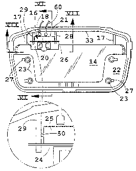
Referring next to Fig. 3, the rear of the housing 11 is shown with the back
plate (described below) removed. Within the housing 11, the switch 16 of the
light
fixture 10 is mounted upside down, suspended from the underside of the top
surface 13
of the housing by two mutually spaced internal walls 28, 29. In a preferred
embodiment, the internal walls 28, 29 are molded to the inside top surface 33
of the
housing 11 and, as best shown in Fig. 4, are situated on either side of an
opening 31
in the top portion 15 of the housing.
Referring to Fig. 5, each internal wall 28, 29 has a pair of generally
parallel
but preferably slightly curving and convergent edges defining a slot 30 which
has an
open end 34 and a closed end 35. Each wall 28, 29 has an upper section 36
which is
molded to the inside top surface 13 of housing 11, and a lower section 37
which is
integrally attached to the upper section 36 at 35. The slots 30 are adapted to
receive
-5-
CA 02242821 1998-08-27
the switch 16 so that it is suspended upside down within the housing 11 (Fig.
3).
The light fixture 10 has a generally U-shaped mounting plate 22 which is
integrally molded along the back edge 19 of the housing 11 (Figs. 3-6
inclusive). The
mounting plate 22 has a series of mounting receptacles 23 adapted to receive
attaching
means (e.g., screws) for holding the light fixture 10 to a supporting surface
(not
shown). Behind the mounting plate 22, fixture 10 preferably includes a back
plate or
rear closure plate (not shown) which, in the preferred embodiment, is
constructed from
a thin piece of sheet metal. The rear closure plate is preferably adapted to
carry the
light bulb of the fixture and, due to its metallic properties, reflects light
emitted from
the bulb. The rear closure plate contains a series of apertures adapted to
receive the
mounting receptacles 23 of the mounting plate 22, each of the mounting
receptacles 23
containing a lip 27 designed to engage the edge of the apertures of the back
plate to
keep the back plate from separating from the housing. The back plate also
contains an
aperture through which the supply wires for the light source may be fed for
connection
to a power source, and the peripheral edges of this aperture preferably has an
integral
rolled edge, made during the stamping operation in which the back plate itself
is
formed, to avoid cutting or abrading such wires without the necessity of using
a
grommet or the like.
The switch 16 has a main body or base 25 (Figs. 6 and 8) having a top surface
24 through which an operating member 20 extends. To operate the switch, the
operating member 20 must be slid from side to side. The switch body 25 has a
mounting plate 26 (Figs. 3 and 7) disposed along top surface 24, with opposed
wing-
like ends which extend outwardly from the base or body 25. These wing-like
ends of
plate 26 are adapted to slide into the slots 30 of the internal walls 28, 29
of the
mounting structure. The slots 30 are positioned in the internal walls 28, 29
so that
when the switch is inserted, the operating member 20 of the switch extends
downwardly below the lower section 37 of each internal wall and in alignment
with the
opening 31 in the housing, where the operating member will be in direct
alignment
with the actuator 12.
As shown in Fig. 3, the switch 16 also has a series of metal terminals 18
which
extend outwardly from the bottom surface 21 of switch body 25 and to which the
wiring 60 is connected. As will be understood, the wiring is also connected to
the
light bulb (not shown).
-6-
CA 02242821 1998-08-27
Figs. 6, 6A, 7, and 8 show the engagement between the components of the
system. The actuator 12 has a base 39 terminating in a pair of spaced legs 42
which
enclose an opening 40. The legs 42 are spear-like, having ramped ends 44
defining
hook-like lips 49 located at the end of base 39. The legs 42 are adapted to
flex
outwardly and are spaced apart a sufficient distance to receive the operating
member
20 within opening 40. During assembly, switch 16 is placed in position as
noted
above and the actuator 12 is inserted through the opening 31 of housing 13. As
the
ramped ends 44 of the actuator legs 42 move along the opposite sides of the
operating
member 20, they flex the legs 42 outwardly but, at the point where the ramps
44 have
moved past operator 20, legs 42 then spring back into place, with the edges of
lips 49
hooked around the operator 20, thus locking the actuator 12 to the switch 16
to prevent
inadvertent disengagement between the two and serve the mutual retention
function
noted above.
As best shown in Figs. 3A, 4A, and 7, the internal walls 28, 29 each have an
elongated rib 50 on their mutually facing sides which, in the preferred
embodiment,
are molded integrally thereto. The ribs 50 and walls 28, 29 are preferably
sized and
spaced so that the ribs 50 engage the sides of the switch body 25 (Fig. 3A)
and flex
the walls 28, 29 slightly outward as the switch is inserted therebetween, to
insure a
snug fit between the switch body 25 and the internal walls 28, 29. In the
preferred
embodiment, the ribs 50 are tapered in cross section and rounded to allow
smooth
sliding engagement between the switch body 24 and the ribs. When so mounted,
the
engagement between the switch body and the ribs stabilizes the switch
laterally and
holds it firmly in position, which aids in assembly of the device and also
helps insure
consistent and proper switch operation.
As best shown in Fig. 8, the base 39 of actuator 12 basically comprises an
elongated tongue or tab of rectangular cross-section, with legs 42 at one end
and head
46 at the other. Immediately below head 46, base 39 is preferably "necked-
down" or
narrowed somewhat at 47, and directly below that, the base 39 has a ramp-like
portion
38 integrally formed in each side. The narrowed portion 37 allows housing
opening
31 to be commensurately reduced in width and facilitates coverage thereof at
all times
(in both positions of travel) by the actuator head 46. The ramps 38 enable
actuator 12
to be self-retaining on housing 11, since they will slightly overlap the top
and bottom
edges of opening 31.
_7_
CA 02242821 1998-08-27
When the actuator is in its fully inserted position (see Fig. 6A), after
having
resiliently deflected these edges to the extent necessary during insertion of
actuator
base 39 through opening 31. This enables one to insert the actuator 12 into a
self-
retaining position before inserting switch 16 during assembly, such that the
actuator 12
need not be manually held in place during insertion of switch 16, and also
helps
provide a smoothly operating, tightly connected and well-assembled product
having no
loose, rattling, or noisy parts.
To assemble the light fixture 10, the wing-like ends of the mounting plate 26
of
the switch 16 are slid into the slots 30 of the internal walls 28, 29. The
switch 16 is
suspended upside down from the internal walls so that, when mounted, the
operating
member 20 of the switch extends downwardly adjacent to and in alignment with
the
opening 31 in the housing 11. With switch 16 so positioned, the actuator 12 is
inserted through the opening 31 of the housing until the legs 42 of the base
37 engage
the operating member 20 of the switch 16. As the actuator 12 is pushed further
into
the opening 31 in housing 11, the legs 42 of the actuator 12 flex outwardly.
Thereafter, when the operating member 20 is fully enclosed by the opening 40
of the
actuator, the legs 42 of the actuator return to their normal position. As
described
above, the actuator remains locked within the housing because the lips 49 of
the
ramped portions 44 of the actuator hook around the rear surfaces of the
operating
member 20 to capture the latter within opening 40. This prevents disengagement
of
the actuator 12 from the switch 16 and from the housing 13 during use, and
also
retains switch 16 in place, since the actuator 12 has a head 46 which is too
large to fit
through housing opening 31 in the event switch 16 is slid rearwardly in slots
30.
Preferably, actuator head 46 has a concave surface 48 opposite the base 38,
which
facilitates manipulation by the user to slide operator 20 and turn the switch
on and off.
In this preferred configuration, the switch 16, being mounted to the inside
top
surface 13 of the polymeric housing, is kept separate from the metal back
plate to
allow easy access to the bulb. In addition, separate structure to connect the
switch is
unnecessary because the switch is not connected to the back plate or the rear
of the
housing. In sum, the instant design efficiently utilizes the limited space
contained
within the housing 11 of the fixture, is relatively inexpensive to manufacture
and
greatly facilitates fast and easy assembly while also maintaining the
integrity of the
mechanical operation of the actuator/switch assembly.
_g_
CA 02242821 1998-08-27
It will become apparent to those skilled in the art that various modifications
to
the preferred embodiment of the invention as described herein can be made
without
departing from the spirit or scope of the invention as defined by the appended
claims.
-9-