Note: Descriptions are shown in the official language in which they were submitted.
CA 02242828 2001-05-16
1
LOCKING DEVICE FOR FURNITURE
The invention relates to a locking device for
furniture, in particular for cabinets, desks, chests,
display cases, base units and the like.
The invention also relates to a locking device
for locking and unlocking two components which can be moved
relative to one another, in particular doors or drawers of
furniture, having a locking element, which can be secured
on a first component, and a locking-element socket, which
can be secured on a second component and can be moved from
a position in which it locks the locking element into an
unlocking position.
Electrically actuable locking devices for
furniture are described in DE 41 O1 744 A1. In a f first
variant, a so-called .spring catch with a catch bolt is
fastened, as locking element, on a movable part of a piece
of furniture, e.g. on a door or a drawer. The locking-
element socket provide~~ is a door opener latch, which is
arranged on a stationary furniture part. A closed position
or open position of the door opener latch for locking or
unlocking the door or a drawer is achieved with the aid of
an armature and an electromagnet.
This known locking device may be equipped either
with an open-circuit door opener latch or with a closed
circuit door opener latch. Optional, switch-over open
circuit operation or closed-circuit operation is not
possible.
In a further variant, the locking element
provided is a locking bolt which, in the direction of its
longitudinal axis, can be moved to a lower, open position
and into a closed position with the aid of a drive. In the
closed position, the :Locking bolt engages in a mating
element, which is fastened on a stationary furniture part.
As a result of the design, the known locking
devices can only be fastened in one position on the
stationary and movable furniture part. Optional
arrangement of the locl~;ing device in accordance with the
CA 02242828 2001-05-16
2
different conditions and furniture configurations is not
possible.
One object of the invention is to provide a
furniture-locking device which can be actuated electrically
and permits an arrangement which is adapted to the various
installation situations, as well as, simultaneously,
monitoring of the open state and locked state.
A further object of the invention is to provide
a locking device which is intended for locking and
unlocking two components, which can be moved relative to
one another, and of which the design permits optionally
closed-circuit operation or open-circuit operation.
According to one aspect of the present invention,
there is provided a locking device for furniture, having a
locking element, which can be fixed on a first furniture
part, having a locking--element socket, which can be fixed
on a second furniture part and can be moved
electromagnetically from a position in which it locks the
locking element into a:n unlocking position, and having a
monitoring device for the closed state and open state,
wherein the locking els~ment provided is a locking pin and
the locking-element socket provided is a locking housing
with a locking slide, wherein the locking housing and the
locking slide have two introduction openings or sockets
which are intended for the locking pin and are arranged so
as to be offset by 90°, and wherein the monitoring device
provided is an indicator element which is arranged at the
point of intersection of the axes of the two introduction
openings of the locking housing.
An essential basic idea of the invention is that
a locking element of defined design interacts with a
locking-element socket which, for optional arrangement of
the locking device, has two sockets for the locking
element. According to the invention, the locking element
provided is a locking ;pin and the locking-element socket
provided is a locking slide arranged in a locking housing.
The locking slide is of virtually cuboidal or cubic design
CA 02242828 2001-05-16
2a
and is arranged in the vicinity of an end side and of an
adjoining housing wall of the locking housing, so as to
ensure a vertical adjusting movement with guidance on at
least one housing wall, in particular on a covering.
According to the invention, two introduction
openings are formed in the locking housing and, in the
unlocking position, these are aligned, or arranged
congruently, with sockets of the locking slide, which
adjoins on the inside.
If in each cane one introduction opening and one
socket, preferably a vertically arranged slot, for a
locking
CA 02242828 1998-09-23
3
pin is provided on an end side and on a front side of the
locking housing and of the locking slide, which abuts on the
inside, then account can be taken of the different instal-
lation situations in each case and the locking device
according to the invention can be fastened as required on a
piece of furniture or else on other lockable structures,
such as safe-deposit boxes, left-luggage lockers or the
like.
A locking position and unlocking position are
achieved, once the locking pin has been introduced, by
vertical adjustment of the locking slide. The locking slide
is actuated by an armature/coil device. The locking slide
is designed such that locking and unlocking operations can
optionally be adjusted in accordance with the closed-circuit
principle (unlocked when not supplied with current) and in
accordance with the open-circuit principle (locked when not
supplied with current).
The closed-circuit principle or open-circuit
principle can be predetermined particularly advantageously
by an armature of the electromagnet being "switched over".
According to the invention, for the purpose of
monitoring the presence of a locking pin, an indicator
element is arranged at the point of intersection, of the
axes of the two introduction openings or of the sockets of
the locking slide and, when a locking pin has been pushed
in, to be precise irrespective of the introduction opening,
said indicator element is displaced counter to a compression
spring and actuates a switch in the process.
The switch is expediently a microswitch and is
connected to a monitoring or alarm system, with the result
that both the locked state, in which the indicator element
is displaced downward counter to the force of a spring
supported on the housing, and the unlocked state, in which
the indicator element is forced by a spring to project into
the socket, are registered.
CA 02242828 1998-09-23
4
The locking pin is designed in the form of a
circular cylinder and projects approximately at right angles
from a fastening flange with fastening openings. It is
advantageous for the locking pin to be fastened releasibly
in a cutout of the fastening flange and for the cutout to be
designed preferably with a relatively large diameter, with
the result that the locking pin can be displaced, in order
to compensate for tolerances, and fastened thereafter. The
locking pin is preferably provided with a frustoconical
introduction region, in order to come into contact with the
introduction opening when the tolerance region is being
utilized.
The locking pin also has a locking groove, in the
vicinity of the fastening-flange end, and an indicator
groove, in the vicinity of the free end. With the locking
slide displaced appropriately, the locking groove and the
adjoining blocking surfaces engage behind the slot opening
of said locking slide, with the result that it is not pos-
sible for the locking pin to be drawn out of the locking
slide and out of the locking housing. This means that a
locking position has been achieved.
The indicator groove serves for the engagement of
the indicator element. For this purpose, the indicator
element, which is designed virtually in the form of a
circular cylinder, has an approximately hemispherical head
region, which is designed to be virtually complementary to
the indicator groove. By virtue of the engagement of the
indicator element in the indicator groove of the locking
pin, the indicator element acts, at the same time, as a
latching element and thus also fulfils the function of a
"latch-in ball".
The locking pin is advantageously provided with a
front introduction region in the form of a truncated cone.
The introduction openings in the locking housing are of
complementary design and taper in the direction of the
locking slide.
CA 02242828 2001-05-16
The loc)cing housing is closed on all sides
and has fastening openings at least in a base surface. The
locking housing is usually fastened in a stationary manner
on a piece of furniture:, while the locking pin is fastened
5 on the movable furniture part. However, it is also
conceivable for this arrangement to be swapped round.
The locking slide is adjusted with the aid of an
armature, which is of bar-like design and can be pivoted
about a pivot axis. The armature is expediently designed
as a single-arm lever. One or even two coils of an
electromagnet is/are arranged in the vicinity of the pivot
axis. A free end region of the armature is fixed, e.g.
suspended, in complementary grooves, namely in an open-
circuit groove or in a closed-circuit groove of the locking
slide. Since fastening can be performed as required, it is
possible to change over from closed-circuit operation to
open-circuit operation and vice versa.
According to another aspect of the present
invention, there is provided a locking device for locking
and unlocking two components which can be moved relative to
one another, in particular doors or drawers of furniture,
having a locking element, which can be secured on a first
component, and a locking-element socket, which can be
secured on a second component and can be moved from a
position in which it docks the locking element into an
unlocking position, wherein the locking element provided is
a locking pin and the locking-element socket provided is a
locking housing with an electrically actuable locking
slide, and wherein, b:~r virtue of setting the relative
positions of interacting locking parts of the locking pin
and of the locking slid~a, it is possible to set optionally
open-circuit operation, in which the locking pin is locked
when the actuation device has not been supplied with
current, and closed-circuit operation, in which the locking
is unlocked when the actuating device has not been supplied
with current. This locl~;ing device, which is mentioned in
the introduction, is deafined in that the locking element
CA 02242828 2001-05-16
5a
provided is a locking pin and the locking-element socket
provided is a locking housing with an electrically actuable
locking slide, and in that, by virtue of setting the
relative positions of interacting locking parts of the
locking pin and of the locking slide, it is possible to set
optionally open-circuit operation, in which the locking pin
is locked when the actuating device has not been supplied
with current, and closed-circuit operation, in which the
locking pin is unlocked when the actuating device has not
been supplied with current.
The possibility of optionally setting open-
circuit operation or c:Losed-circuit operation means that
the necessary range of variants and types is reduced to a
considerable extent. Setting can be carried out when the
locking device is firsit fitted on components, furniture,
safedeposit
CA 02242828 2001-05-16
6
boxes, left-luggage lockers, drawers and the like or else
is straightforward to change over at a later stage as
required.
Advantageous configurations of the invention are
specified in the associated dependent claims.
The locking d~svice according to the invention and
the functioning thereof are explained in more detail below
by way of exemplary s:mbodiments and with reference to
drawings, in which, schematically:
Figure 1 shows a view of an inventive locking
device with a locking housing, of which part of the cover
plate has been removed,, having a locking pin arranged on
the end side and outside the locking housing:
Figure 2 show; an end view of the locking housing
in accordance with arrow II according to Figure l, having
a locking pin arranged in the region of the cover plate and
outside the locking housing;
Figure 3 shows a locking device according to the
invention with a locking pin which has been introduced on
the end side and is in the unlocked position (open-circuit
principle)
Figure 4 shows an end view of the locking housing
with a locking pin which has been introduced on the cover
plate side and is in t:he unlocked position (open-circuit
principle);
Figure 5 shows a locking device according to the
invention with a locking pin which has been introduced on
the end side and is in the locked position (open-circuit
principle);
Figure 6 shows an end view of the locking housing
with a locking pin which has been introduced on the cover-
plate side and is in the locked position (open-circuit
principle):
Figure 7 show: a locking device according to the
invention with a locking pin which has been introduced on
the end side and is in t:he locked position (closed-circuit
principle):
CA 02242828 1998-09-23
7
Figure 8 shows an end view of a locking housing
with a locking pin which has been introduced on the cover-
plate side and is in the locked position (closed-circuit
principle);
Figure 9 shows a locking device according to the
invention with a locking pin which has been introduced on
the end side and is in the unlocked position (closed-circuit
principle);
Figure 10 shows an end view of the locking housing
with a locking pin which has been introduced on the cover
plate side and is in the unlocked position (closed-circuit
principle);
Figure 11 shows, in a side view according to
Figure 1, a further exemplary embodiment of the locking
device according to the invention;
Figures 12(a) to 12(d) show four views of a
further embodiment of a locking pin for the locking device
illustrated in Figure 11; and
Figures 13 (a) to 13 (d) show four views of the
locking pin of the locking device illustrated in Figure 11.
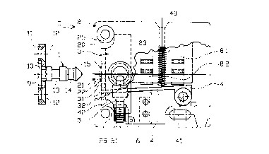
The inventive locking device according to Figures
1 and 2 has a locking pin 1 as a locking element and a
locking housing 2 as a locking-element socket as well as a
locking slide 3 which is received in said housing. The
locking housing 2 is of approximately cuboidal design and is
closed at the front, or top side by a cover plate 23.
In Figures 1, 3, 5, 7 and 9, part of the cover-
plate 23 has been removed in a bottom right-hand region.
Moreover, it is only those features which are necessary for
understanding the locking device which are illustrated. The
locking housing 2 has two introduction openings 21, 22 for
optional arrangement of the locking device or locking pin 1.
Both the end introduction opening 21 and the second
introduction opening 22 in the cover plate 23, said second
introduction opening being arranged at the same height and
at the same distance from a left-hand housing edge, are
CA 02242828 1998-09-23
8
respectively aligned with sockets 33 and 34 in the locking
slide 3, which in this exemplary embodiment is arranged in
the left-hand end region of the locking housing 2. The two
sockets 33, 34 for an optionally arranged locking pin 1 are
designed as slots. The introduction openings 21, 22,
aligned with the slots 33, 34 in Figures 1 and 2, of the
locking housing 2 run conically in the direction of the
interior and of the locking slide 3.
The locking slide 3 is guided displaceably on the
inside of the cover plate 23 by way of a securing plate 35
and, as can be gathered from Figure 1, has arcuate recesses
on the left which correspond to the fastening regions 25 of
the locking housing 2.
Figure 2 shows that locking slide 3 is designed to
be of approximately the same depth as the interior of the
locking housing 2. Actuation of the locking slide 3 takes
placed electromagnetically with the aid of a set of coils
8.1 and 8.2 and an armature 4, which interacts with the set
of coils 8.1, 8.2. This armature 4 is designed as a single
arm lever, of which the pivot axis 41 is arranged approxi-
mately in the region of the right-hand coil 8.1. The
armature 4 can be arranged, for example suspended in an
open-circuit groove 31 or in a closed-circuit groove 32 by
way of a free end region 42. The open-circuit and closed-
circuit grooves 31, 32 are designed, in a rear region 36 of
the locking slide 3, to be approximately complementary to
the end region of the armature 4. In Figure 1, the bar-like
armature 4 has been suspended, for closed-circuit operation,
in the closed-circuit groove 32. Suspension of the armature
4 in the closed-circuit groove 32 or open-circuit groove 31
means that the locking device can be changed over as re-
quired. With the no-current closed-circuit operation in
Figure 1, the locking pin 1 can be introduced. In Figure 1,
the locking pin 1 is introduced into the slot 33 of the
locking slide 3 via the end side 20 and the introduction
opening 21, and in Figure 2 it is introduced into the slot
CA 02242828 1998-09-23
9
34 of the locking slide 3 via the introduction opening 22 in
the cover plate 23 of the locking housing 2.
In the present exemplary embodiment, the locking
pin 1 is received "with play" in a cutout 10 of a fastening
flange 11, the cutout 10 being designed in the form of a
step corresponding to a fastening foot 9 of the locking pin
1. The relatively large diameter of the cutout 10 permits
displacement of the locking pin 1 in the fastening flange
11, thus ensuring tolerance compensation. Fastening of the
locking pin 1 in the fastening flange 11 can take place in
a known manner.
In the region of the fastening flange 11, the
locking pin 1 is fastened on the corresponding furniture
part via fastening openings 12. It is usually the case that
the locking pin 1 is arranged on a movable furniture part,
while the locking housing 2 with locking slide 3 and an
indicator element 5 is fastened on a fixed furniture part.
However, it is also possible for this arrangement to be
swapped round.
The locking pin 1 has two grooves 13, 14 in a
cylindrical region. The first of these grooves is a locking
groove 13, in which the locking slide 3 engages when it is
displaced into a locking position with the aid of the arma-
ture 4. An indicator groove 14 is provided in the vicinity
of a head-side introduction region 15, which is in the form
of a truncated cone, and serves for receiving the indicator
element 5. The frustoconical introduction region 15 per-
mits, by way of the introduction slopes, introduction into
the introduction openings 21, 22 even with utilization of a
tolerance region in the case of the displaceable arrangement
in the cutout 10.
The indicator element 5 is designed as an indica-
tor slide which is arranged so as to be vertically displace-
able counter to the force of an indicator spring 51, which
is supported on the housing 2. Whenever a locking pin 1 is
introduced through the end introduction opening 21 or
CA 02242828 1998-09-23
through the cover-plate introduction opening 22, the indi-
cator element 5, resting in the indicator groove 14, is
forced downward. It thus also assumes a latching-in func-
tion in addition to the monitoring function. As it is being
5 forced downward, the indicator element 5 activates a micro-
switch 6, which is arranged immediately beside the indicator
element 5 and can be connected to an alarm or monitoring
system.
The illustrations in the following Figures 3 to
10 10, correspond to Figures 1 and 2 as far as the design of
the locking device is concerned. These figures merely
illustrate different operating states, and the same desig-
nations are therefore used for the same features in the
following figures.
Figure 3 shows a locking pin 1 which has been
introduced into the locking housing 2, the locking pin 1
having been introduced into the end introduction opening 21
of the locking housing 2 and into the end socket or the slot
33 of the locking slide 3. The cover-plate introduction
opening 22 is used in the locking arrangement according to
Figure 4. In Figure 3, this cover-plate introduction
opening 22 makes it possible to see the interaction of the
indicator element 5 and the indicator groove 14 of the
locking pin 1. The virtually spherical head 50 of the
indicator element 5 engages in the indicator groove 14 and
assumes a certain latching function. Figure 3 and Figure 4
show that, in that position of the locking slide 3 which is
illustrated, the locking pin 1 is not locked and can there-
fore be drawn out of the locking slide 3 and the locking
housing 2 without obstruction. With such an arrangement, a
drawer or a door can be opened.
The locking device according to Figures 3 and 4
operates in accordance with the open-circuit principle,
because the armature 4 is arranged with its end region 42 in
the open-circuit groove 31. The set of coils 8.1, 8.2 has
CA 02242828 1998-09-23
11
been supplied with current and activates the armature in the
direction counter to the force of an armature spring 40.
The functioning of the indicator element 5 becomes
clear upon comparison of Figures 1, 3 and 2, 4. While the
indicator element 5 in Figures 1 and 2 cannot be forced
downward because the locking pin 1 has not been introduced,
the indicator spring 51 in Figures 3 and 4 and in the rest
of the figures is compressed and the hemispherical head 50
rests in the indicator groove 14.
Figures 5 and 6 show the locking device according
to Figures 3 and 4, but the coils 8.1 and 8.2 have not been
supplied with current . The armature 4 is forced downward by
the armature spring 40, and the locking slide 3 is adjusted
downward by way of the end region 42 of the armature 4.
This adjustment can be seen, in particular, from the posi-
tion of the securing plate 35 and of the slots 33, 34. At
the same time, it becomes clear that the locking pin 1, with
its locking groove 13 is arranged eccentrically in the
respective slot 33, 34 and a blocking position has been
reached. In the operating state of Figures 5 and 6, the
locking pin 1 cannot be drawn out. The corresponding drawer
or door are locked and cannot be opened. It is only when
the set of coils 8 has been supplied with current again, and
when the armature 4 according to Figures 3 and 4 is acti-
vated, that the locking slide 3 is adjusted upward again,
that is to say in the direction counter to the arrow VI
according to Figure 6, with the result that the locking
position of the locking slide 3 is overcome.
Figures 7 to 10 show a locking device in accord
ance with the closed-circuit principle. The armature 4 is
suspended in the closed-circuit groove 32 by way of its free
end region 42 (see Figures 7 and 9). The current-carrying
set of coils 8.1 and 8.2 activates the armature 4, according
to Figure 7, and as a result the locking slide 3 is dis
placed upward (see arrow VIII in Figure 8). The respective
slot 33 or 34 is no longer aligned with the adjacent intro-
CA 02242828 1998-09-23
12
duction opening 21, 22 of the locking housing 2, but rather
blocks the path of the locking pin 1 in the region of the
locking groove 13, with the result that said pin cannot be
drawn out of the locking housing 2. When the set of coils
8.1, 8.2 is not supplied with current (see Figures 9 and
10), the armature spring 40 forces the armature 4 downward
and, with it, the locking slide 3 is moved downward (see
arrow X in Figure 10). The slot 33 in the end side 20 of
the locking slide 3 is aligned with the end introduction
opening 21 of the locking housing 2, and the slot 34 and the
introduction opening 22 are likewise aligned (Figure 9). It
is possible for the locking pin 1 to be drawn out. As said
pin is being drawn out, it is not obstructed in any way by
the indicator element 5 with its hemispherical head 50.
Moreover, the locking pin 1 is of bevelled design in the
region of the indicator groove 14, with the result that it
can slide over the indicator element 5 as it is guided out
of the housing.
A further exemplary embodiment of the locking
device according to the invention is illustrated in Figure
11. The ways in which this locking device differs from the
previous examples are described in more detail hereinbelow.
The locking pin 61 of this locking device (see
also Figures 13a to 13d) is constructed in largely the same
way as the locking pin 1, which is illustrated in Figures 1
and 2. It has a cylindrical central section 62, which is
adjoined, toward the tip of the pin, by annular indicator
groove 14 and a head-side introduction region 15, which is
in the form of a truncated cone. The central section 62 is
adjoined, in the direction of the fastening foot 9, by the
locking groove 13, which has already been described. The
fastening foot 9 is received with radial play in the step-
like cutout 10 of the fastening flange 11. In the circular
fastening foot 9, a recess 64, for example a semicircular
milled section, extends radially inward from the circum-
ference (see Figure 13c). The fastening flange 11 has a
CA 02242828 1998-09-23
13
nose 65 which corresponds to the recess 64, is designed to
project toward the longitudinal axis in the cutout 10 and
engages with play in the recess 64 on the fastening foot 9
of the locking pin 61. When the fastening flange 11 has
been screwed tight, the locking pin 61 is thus secured
against turning about its longitudinal axis.
Toward the locking groove 13, the cylindrical
central section 62 has a bevel 66 with an angle a of, for
example, 60°, the bevel 66 being formed over approximately
180° on the circumference of the central section 62 (see
Figure 13b) . Otherwise, a locking surface 67 with a cir-
cumferential edge 68 remains on the side of the central
section 62.
The locking slide 3 is guided displaceably in the
locking housing 2 in the manner which was described by way
of the first exemplary embodiment. In the bottom position
(illustrated), it is retained by the armature 4 which is
suspended, at its free, front end 42, in a recess 43 in the
locking slide 3 and is forced downward, about its pivot axis
41, via the armature spring 40 when coils 8.1 and 8.2 have
not been supplied with current.
In this exemplary embodiment, the two sockets 33,
34 of the locking slide 3 are illustrated as rectangular
recesses with rounded corners. An inner receiving space in
a central part of the locking housing 2 for the inserted
locking pin 61 is formed by two bores 26 and 27 which inter-
sect at right angles and are respectively arranged coaxially
with the end introduction opening 21 and the cover-side
introduction opening 22 (not depicted in Figure 11).
On a common axis 28, which leads through the point
of intersection 29 of the two bores 26 and 27, two indicator
elements 5 or slides are arranged opposite one another in
the locking housing 2. Each indicator element 5 is forced,
by an indicator spring 51, into the illustrated position, in
which the virtually spherical head 50 projects into the
CA 02242828 1998-09-23
14
receiving space, formed by the bores 26, 27, for the locking
pin 61.
When a furniture door or the like which has been
equipped with the locking device illustrated is closed,
then, depending on the arrangement, the locking pin 61 is
pushed through the end introduction opening 21 or the cover-
side introduction opening 22 and the associated socket 33 or
34, respectively, in the locking slide 3. In this case, the
frustoconical introduction region 15, in accordance with the
illustration in Figure 11, forces the top side of the socket
33 (this is indicated by the arrow designated 33), and thus
the locking slide 3, upward until, in the fully pushed-in,
closed position, the central section 62 of the locking pin
61 is arranged within the locking slide 3, with the result
that the locking slide 3, which is subjected to spring pre-
stressing by the armature 4, is forced downward and its
locking protrusion 37 engages in the locking groove 13.
Furthermore, the spherical heads 50 of the two indicator
elements 5 have first of all been forced outward, counter to
the force of the indicator springs 51, by the frustoconical
introduction region 15 and are then latched in the indicator
groove 14, in the closed position. Since the locking pro
trusion 37 butts axially against the locking surface 67 of
the locking pin 61, the locking pin 61 cannot be drawn out
of the locking housing 2.
For unlocking purposes, the coils 8.1 and 8.2 are
supplied with current and activate the armature 4, as a
result of which the locking slide 3 is pushed upward (accor-
ding to Figure 11). The locking protrusion 37, which moves
along therewith, is drawn back out of the locking groove 13
of the locking pin 61, with the result that the axially
directed, mechanical blocking is then eliminated and the
locking pin 61 is retained merely by the indicator elements
or slides 5, which have a latching function. This realizes
locking and unlocking in accordance with the open-circuit
principle (locked when not supplied with current).
CA 02242828 1998-09-23
The exemplary embodiment illustrated makes it
possible for the locking device to be used alternatively in
accordance with the closed-circuit principle (unlocked when
not supplied with current). For operation in accordance
5 with the closed-circuit principle, the locking pin 61 is
fitted in a position in which, together with the fastening
flange 11, it is arranged so as to be turned through 180°
about its longitudinal axis 17 in relation to the illustra-
tion in Figure 11. Both the bevel 66 and the recess 64 as
10 well as the nose 65 are then arranged on the opposite side
(the top side according to Figure 11).
When, then, the locking pin 61 is pushed in
through the end introduction opening 21 and the associated
socket 33 in the locking slide 3, then, with simultaneous
15 displacement of the locking slide 3, the top side of the
socket 33 slides over the frustoconical introduction region
15, the indictor groove 14, the narrow central section and
the bevel 66 until it is located in the locking groove 13.
At the same time, the indicator elements 5 are latched in
the indicator groove 14. In this case, rather than butting
against the locking surface 67 in a blocking manner, the
locking protrusion 37 can slide on the bevel 66, as the
locking pin 61 is drawn out, and pushes the locking slide 3
upward.
For the purpose of locking the locking pin 61, the
set of coils 8.1 and 8.2 is supplied with current. The
armature 4 displaces the locking slide 3 into its top posi-
tion. Thereafter, the locking protrusion 37', located
opposite at the socket 33, engages in the locking groove 13
and, at the locking surface 67, forms a mechanical blocking
means against the locking pin 61 being drawn out.
A further exemplary embodiment of the locking
device according to the invention has a locking pin 71,
according to Figures 12a to 12d, which in contrast to the
locking pin 61, illustrated in Figures 13a to 13d, has on
its front section, from the central section 62 toward the
CA 02242828 1998-09-23
16
tip of the pin, a conical introduction section 63 with a
cone angle of, for example, 30°. With the arrangement and
functioning otherwise being comparable to those of Figure
11, the locking pin 71, once pushed into the locking house
2, is kept locked in the manner described, by the blocking
contact between the locking protrusion 37 and the locking
surface 67, in accordance with the open-circuit principle
(locked when not supplied with current).
When the set of coils 8.1 and 8.2 is supplied with
current, the locking slide 3 is pushed upward by the arma
ture 4, with the result that the axial blocking is elimi
nated. By virtue of the two indicator elements 5, which
have their heads 50 forced, under prestressing, by the
springs 51 against the conical introduction section 63 of
the locking pin 71 in the radial direction, an axial force
component is exerted on the conical introduction section 63,
as a result of which, depending on the installation situa-
tion, the locking pin 71 is forced out of the housing 2 by
a certain distance.
Supplying the set of coils 8.1 and 8.2 with cur-
rent thus results not just in unlocking, but also in the
locking pin 71 being forced out, this providing a visual
indication of the unlocking position.
In this exemplary embodiment, only the open
circuit principle is used, the locking pin 71 being fitted
in a position with the bevel 66 beneath the longitudinal
axis 17 (see Figure 11). With the closed-circuit principle
(open when not supplied with current), the unlocked locking
pin 71, once pushed into the housing 2, would immediately be
forced out again by the two spring-loaded indicator elements
5.
The housing 2 illustrated in Figure 11 has a coil
former with two coils 8.1 and 8.2 in an arrangement for
optional series connection (24 V) or parallel connection (12
V). In accordance with these two arrangements, the coils
are connected to four terminals of contact strips 44. The
CA 02242828 1998-09-23
17
desired arrangement is selected by appropriately connecting
power leads to the contact strip 44.
Instead of the two indicator elements 5 described,
it is also possible, while maintaining the same functioning,
for just one indictor element 5 to be provided. A micro
switch for sensing the position may be provided on one indi-
cator element 5 or on the two indicator elements 5.