Language selection

Search

Patent 2242934 Summary

Third-party information liability

Some of the information on this Web page has been provided by external sources. The Government of Canada is not responsible for the accuracy, reliability or currency of the information supplied by external sources. Users wishing to rely upon this information should consult directly with the source of the information. Content provided by external sources is not subject to official languages, privacy and accessibility requirements.

Claims and Abstract availability

Any discrepancies in the text and image of the Claims and Abstract are due to differing posting times. Text of the Claims and Abstract are posted:

  • At the time the application is open to public inspection;
  • At the time of issue of the patent (grant).
(12) Patent Application: (11) CA 2242934
(54) English Title: APPARATUS FOR ISOLATING AND EXERCISING THE ABDOMINAL MUSCLES
(54) French Title: APPAREIL POUR ISOLER ET FAIRE TRAVAILLER LES MUSCLES ABDOMINAUX
Status: Deemed Abandoned and Beyond the Period of Reinstatement - Pending Response to Notice of Disregarded Communication
Bibliographic Data
Abstracts

English Abstract


An apparatus for isolating the abdominal muscles and
effectively loading them during exercise is disclosed. The
device supports the user's body in a position which allows
for trunk flexion; however, it forces the user's knee flexor
and hip extensor muscles to contract, relaxing the hip flexor
muscle, and isolating the abdominal muscles. Consequently,
the only muscles exercised during the trunk flexion are the
abdominal muscles.


Claims

Note: Claims are shown in the official language in which they were submitted.

WHAT IS CLAIMED IS:
1. An apparatus for an isolation mechanism operative to
isolate a user's abdominal muscles and further to
prevent pelvic tilt and stabilize the lower back during
exercise, which isolation mechanism comprises:
(a) a foot support bracket;
(b) a frame providing support for said foot support
bracket;
(c) a resistance mechanism, coupled to said frame,
operative to supply resistance against forces applied
to said foot support bracket by said user's feet and
further to contract said user's knee flexor and hip
extensor muscles, isolating said user's abdominal
muscles; and
(d) an adjustment point, coupled to said frame,
operative to adjust the position of said foot support
bracket so as to accommodate different users and body
movement during said exercise.
9

2. A trunk flexion exercise apparatus comprising:
(a) a bench operative to support said user's back and
hips during said trunk flexion exercise; and
(b) an isolation mechanism mounted under one end of
said bench, which isolation mechanism further
comprises:
(i) a foot support bracket;
(ii) a frame providing support for said foot
support bracket;
(iii) a resistance mechanism, coupled to said frame,
operative to supply resistance against forces
applied to said foot support bracket by said
user's feet and further to contract said user's
knee flexor and hip extensor muscles, isolating
said user's abdominal muscles; and
(iv) an adjustment point, coupled to said frame,
operative to adjust the position of said foot
support bracket so as to accommodate different
users and body movement during said exercise;
10

which isolation mechanism is operative to contract
said user's knee flexor and hip extensor muscles,
isolating said user's abdominal muscles in a manner
which stabilizes said user's pelvis and lower back
during said trunk flexion exercise.
3. An apparatus according to claim 2, wherein said bench
is one of inclined, declined and curved so as to provide
a hyper-extended starting position for said trunk
flexion exercise.
4. An apparatus according to claim 2, wherein said bench
and said isolation mechanism are adjustable so as to
accommodate users with different body sizes and
movements.
5. An apparatus according to claim 1, wherein said
resistance mechanism is constructed using springs.
6. An apparatus according to claim 1, wherein said
resistance mechanism is constructed using compressed
air.
11

7. An apparatus according to claim 1, wherein said
resistance mechanism is constructed using a weight and
pulley arrangement.
8. An apparatus according to claim 1, wherein said
resistance mechanism is comprised of:
(a) a first resistance mechanism, coupled to said
frame, operative to supply resistance in a first
direction against forces applied to said foot support
bracket by said user's feet; and
(b) a second resistance mechanism, coupled to said
frame, operative to supply resistance in a second
direction against forces applied to said foot support
bracket by said user's feet, said second direction
having a component orthogonal to said first
direction.
9. An apparatus according to claim 8, wherein said first
and second resistance mechanisms are constructed using
springs.
12

10. An apparatus according to claim 8, wherein said first
and second resistance mechanisms are constructed using
compressed air.
11. An apparatus according to claim 8, wherein said first
and second resistance mechanisms are constructed using a
weight and pulley arrangement.
12. An upper body weight training exercise apparatus
comprising:
(a) a bench operative to support said user's back and
hips during said upper body weight training exercise;
and
(b) an isolation mechanism mounted under one end of
said bench, which isolation mechanism further
comprises:
(i) a foot support bracket;
(ii) a frame providing support for said foot
support bracket;
13

(iii) a resistance mechanism, coupled to said frame,
operative to supply resistance against forces
applied to said foot support bracket by said
user's feet and further to contract said user's
knee flexor and hip extensor muscles, isolating
said user's abdominal muscles; and
(iv) an adjustment point, coupled to said frame,
operative to adjust the position of said foot
support bracket so as to accommodate different
users and body movement during said exercise;
which isolation mechanism is operative to contract
said user's knee flexor and hip extensor muscles,
isolating said user's abdominal muscles in a manner
which stabilizes said user's pelvis and lower back
during said upper body weight training exercise.
13. An apparatus according to claim 12, wherein said
bench is one of inclined, declined and curved so as to
provide a modified upper body weight training exercise.
14. An apparatus according to claim 12, wherein said
bench and said isolation mechanism are adjustable so as
14

to accommodate users with different body sizes and
movements.
15

Description

Note: Descriptions are shown in the official language in which they were submitted.


CA 02242934 1998-07-06
APPARATUS FOR ISOLATING AND EXERCISING THE ABDOMINAL
MUSCLES
FIELD OF THE INVENTION
The present invention relates to an apparatus for
isolating the abdominal muscles so as to stabilize the pelvis
and lower back during exercise. More specifically, it
relates to a device that facilitates trunk flexion exercise
(the sit-up motion) without permitting contraction of the hip
flexor muscles.
BACKGROUND OF THE INVENTION
The benefits of strong abdominal muscles have long
been recognized by sports and physical medicine professionals
as well as by the average person. One particular advantage
of strong abdominal muscles is the prevention and reduction
of associated lower back problems. Traditional methods of
exercising the abdominal muscles are not only largely
ineffective, but exacerbate most lower back injuries.
The most common exercise for loading the abdominal
muscles is trunk flexion, traditionally achieved using the
well known sit-up exercise. The sit-up involves the user
1

CA 02242934 1998-07-06
lying on their back, knees bent and toes hooked under a solid
object for stabilization and then raising their torso until
they are sitting up. Commonly, several repetitions of the
sit-up exercise are performed. Alternatively, a sit-up can
be performed using only the weight of the legs for
stabilization.
Traditional abdominal exercises (sit-ups) result in
trunk flexion being performed by the hip flexor muscles, the
same muscles used to raise the knees when walking or stair
climbing. The drawback with the traditional sit-up is that
the desired motion of the exercise, trunk flexion, is not
effected by contraction of the abdominal muscles.
The hip flexor muscles are attached to the pelvic
girdle and when they contract a torque is produced about the
hip joint. This torque causes the pelvis to tilt forward and
flex the trunk. In this position, the lower back is unstable
and the resulting shear forces applied to the vertebra cause
undesirable stress on the lower back which can cause injury
over time. Isometric contraction refers to a type of muscle
contraction where the muscles are loaded but no motion occurs
(an effect similar to pushing against an immovable object).
If sufficiently strong, isometric contraction of the
2

CA 02242934 1998-07-06
abdominal muscles tends to offset these shear forces placed
on the veterbra, thereby stabilizing the lower back.
Accordingly, the principal object of this invention
is to provide a means of stabilizing the body during a trunk
flexion abdominal exercise in a manner that does not permit
the hip flexor muscles to contract, thereby isolating the
desired abdominal muscle contraction. Further objects of the
invention include providing a means to cause the muscles
associated with knee flexion and hip extension to contract,
thereby forcing the hip flexors to relax. This helps to
stabilize the pelvis (i.e. preventing pelvic tilt) and
stabilize the lumbar region of the lower back during trunk
flexion and typical upper body weight training exercises.
SUMMARY OF THE INVENTION
The following is a brief description of the
invention, its parts and its functionality.
The present invention is a system providing an
isolation mechanism operative to isolate a user's abdominal
muscles and further to prevent pelvic tilt and stabilize the
lower back during exercise. The isolation mechanism
comprises a foot support bracket and a frame which supports
3

CA 02242934 1998-07-06
the bracket. Coupled to the frame is a resistance mechanism,
which is operative to resist force applied by the user's feet
to the aforementioned foot support bracket and further to
contract the user's knee flexor and hip extensor muscles,
isolating their abdominal muscles. The device is equipped
with an adjustment point which is used to change the
orientation of the orthogonal resistance mechanisms for
various user body shapes and movements.
In the preferred embodiment, the isolation mechanism
may be mounted underneath one end of a bench which supports
the user's back and hips while they perform a trunk flexion
exercise. The user may place their feet on the foot support
bracket of the isolation mechanism and then exert force
against the resistance mechanisms. This force applied by the
user may be operative to contract~the user's knee flexor and
hip extensor muscles in a manner which stabilizes their
pelvis and lower back during trunk flexion exercise. In this
position, the hip flexor muscles cannot be contracted and
only the abdominal muscles may be used to perform trunk
flexion.
The bench supporting the user may be inclined,
declined or curved so as to provide a hyper-extended starting
position for the trunk flexion exercise. The bench and
4

CA 02242934 1998-07-06
isolation mechanism may be adjustable so as to accommodate
users with different body sizes and movements.
The resistance mechanisms may be constructed in a
variety of styles including tension and compression springs,
elastomer materials, air compression means, and even weights
and pulleys.
The resistance mechanism may be comprised of a first
resistance mechanism oriented in a first direction and a
second resistance mechanism oriented in a second direction
where the second direction has a component which is
orthogonal to the first direction. Both resistance
mechanisms are coupled to the frame in a manner which resists
forces applied to the foot support bracket by the user's
feet. Again the resistance mechanism may be constructed from
a variety of styles including tension and compression
springs, elastomer materials, air compression means, and even
weights and pulleys.
In another aspect of the invention, the isolation
mechanism may be mounted underneath one end of a bench which
supports the user's back and hips while they perform a
typical upper body weight training exercise such as a bench
press or dumbbell flies. The user may place their feet on
5

CA 02242934 1998-07-06
the foot support bracket of the isolation mechanism and then
exert force against the resistance mechanisms. This force
applied by the user may be operative to contract the user's
knee flexor and hip extensor muscles, isolating their
abdominal muscles in a manner which stabilizes their pelvis
and lower back during the upper body weight training
exercise. Again, the bench can be inclined, declined or
curved so as to provide a hyper-extended starting position
for the trunk flexion exercise. The bench and isolation
mechanism may be adjustable so as to accommodate users with
different body sizes and movements.
BRIEF DESCRIPTION OF THE DRAVWINGS
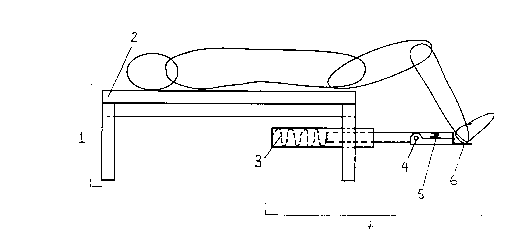
Fig. 1-a and 1-b show top and side views,
respectively, of the apparatus for the preferred embodiment,
the side view depicting a person lying on the device and
manipulating the isolation mechanism with their feet.
Fig. 2 exhibits detail of two possible embodiments of
the isolation mechanism. Fig. 2-a displays a tension spring
design and Fig. 2-b portrays a compression spring design.
Fig. 3 and Fig. 4 exhibit detail of other possible
embodiments of the isolation mechanism. Fig 3 displays a
6

CA 02242934 1998-07-06
compressed air piston design and Fig. 4 portrays a weight and
pulley design.
DESCRIPTION OF THE PREFERRED EMBODIMENT
Fig. 1-a and 1-b show top and side views,
respectively, of the apparatus for the preferred embodiment.
Referring to Fig. 1-a and 1-b, the device consists of a
bench 1 covered by a pad or cushion 2. The user lies on
their back atop the bench 1. The bench 1 is equipped with an
isolation mechanism 7 affixed underneath one end of the bench
1. The user places their feet in the foot support bracket 6,
which has appropriate surfaces for the exertion of force
using the posterior of the heels and the soles of the feet.
The forces exerted by the user are countered by spring 5
which resists one component of the user applied force and
spring 3 which opposes a second component of the user applied
force. The isolation mechanism 7 is also provided with a
pivot point 4 which permits various orientations for the user
applied force. The isolation mechanism 7 and the
corresponding user applied forces serve to cause the knee
flexor and hip extensor muscles to contract and further cause
the hip flexor muscles to relax, effectively isolating the
abdominal muscles during trunk flexion.
7

CA 02242934 1998-07-06
Fig. 2-a and Fig. 2-b show detail of possible
embodiments of the isolation mechanism 7. Fig 2-a depicts a
device, wherein the isolation mechanism 7 is implemented
using an adjustment point 4 which is distal from the foot
support bracket 6. Springs 3 and 5 are tension springs which
resist the orthogonal components of the user applied forces.
A stroke limiter 8 is provided to control the range of motion
of the isolation mechanism 7. Fig. 2-b exhibits a device
wherein the isolation mechanism 7 is implemented using an
adjustment point 4 which is closer to the foot support
bracket 6. Spring 5 is once again a tension spring which
resists one component of the user applied force, and spring 3
is a compression spring which resists a second component of
the user applied force. The device is also equipped with a
stroke limiter 8 as in Fig. 2-a.
Many other possible embodiments exist which are not
shown in the drawings. The bench 1 may be designed to
incline, decline or curve the user's body to provide various
starting positions. Furthermore, the resistance mechanism
may be accomplished by means other than springs, including
weights and pulleys, compressed air, and elastomer materials.
Fig. 3 and Fig 4 depict compressed air piston and weight and
pulley designs.
8

Representative Drawing
A single figure which represents the drawing illustrating the invention.
Administrative Status

2024-08-01:As part of the Next Generation Patents (NGP) transition, the Canadian Patents Database (CPD) now contains a more detailed Event History, which replicates the Event Log of our new back-office solution.

Please note that "Inactive:" events refers to events no longer in use in our new back-office solution.

For a clearer understanding of the status of the application/patent presented on this page, the site Disclaimer , as well as the definitions for Patent , Event History , Maintenance Fee  and Payment History  should be consulted.

Event History

Description Date
Inactive: Agents merged 2011-07-06
Application Not Reinstated by Deadline 2005-07-06
Time Limit for Reversal Expired 2005-07-06
Deemed Abandoned - Failure to Respond to Maintenance Fee Notice 2004-07-06
Inactive: Final fee received 2004-04-20
Pre-grant 2004-04-20
Notice of Allowance is Issued 2003-10-20
Letter Sent 2003-10-20
Notice of Allowance is Issued 2003-10-20
Inactive: Approved for allowance (AFA) 2003-09-30
Amendment Received - Voluntary Amendment 2003-08-29
Amendment Received - Voluntary Amendment 2003-08-05
Inactive: S.30(2) Rules - Examiner requisition 2003-07-24
Amendment Received - Voluntary Amendment 2003-05-26
Inactive: S.30(2) Rules - Examiner requisition 2002-12-18
Inactive: Office letter 2001-08-03
Amendment Received - Voluntary Amendment 2001-02-09
Application Published (Open to Public Inspection) 2000-01-06
Inactive: Cover page published 2000-01-05
Inactive: Entity size changed 1999-02-25
Letter Sent 1999-02-11
Inactive: Single transfer 1999-02-08
All Requirements for Examination Determined Compliant 1999-01-11
Request for Examination Requirements Determined Compliant 1999-01-11
Request for Examination Received 1999-01-11
Inactive: First IPC assigned 1998-10-29
Classification Modified 1998-10-29
Inactive: IPC assigned 1998-10-29
Inactive: Filing certificate - No RFE (English) 1998-09-17
Application Received - Regular National 1998-09-15

Abandonment History

Abandonment Date Reason Reinstatement Date
2004-07-06

Maintenance Fee

The last payment was received on 2003-06-16

Note : If the full payment has not been received on or before the date indicated, a further fee may be required which may be one of the following

  • the reinstatement fee;
  • the late payment fee; or
  • additional fee to reverse deemed expiry.

Patent fees are adjusted on the 1st of January every year. The amounts above are the current amounts if received by December 31 of the current year.
Please refer to the CIPO Patent Fees web page to see all current fee amounts.

Fee History

Fee Type Anniversary Year Due Date Paid Date
Application fee - small 1998-07-06
Request for examination - small 1999-01-11
Registration of a document 1999-02-08
MF (application, 2nd anniv.) - standard 02 2000-07-06 2000-06-26
MF (application, 3rd anniv.) - standard 03 2001-07-06 2001-06-21
MF (application, 4th anniv.) - standard 04 2002-07-08 2002-06-27
MF (application, 5th anniv.) - standard 05 2003-07-07 2003-06-16
Final fee - standard 2004-04-20
Owners on Record

Note: Records showing the ownership history in alphabetical order.

Current Owners on Record
MED-EX DIAGNOSTICS OF CANADA INC.
Past Owners on Record
JAMES A. MCARTHUR
Past Owners that do not appear in the "Owners on Record" listing will appear in other documentation within the application.
Documents

To view selected files, please enter reCAPTCHA code :


To view images, click a link in the Document Description column. To download the documents, select one or more checkboxes in the first column and then click the "Download Selected in PDF format (Zip Archive)" or the "Download Selected as Single PDF" button.

List of published and non-published patent-specific documents on the CPD .

If you have any difficulty accessing content, you can call the Client Service Centre at 1-866-997-1936 or send them an e-mail at CIPO Client Service Centre.


Document
Description 
Date
(yyyy-mm-dd) 
Number of pages   Size of Image (KB) 
Representative drawing 2000-01-03 1 5
Claims 2003-05-25 7 242
Claims 2003-08-28 6 173
Abstract 1998-07-05 1 14
Description 1998-07-05 8 274
Claims 1998-07-05 7 146
Drawings 1998-07-05 4 112
Filing Certificate (English) 1998-09-16 1 174
Acknowledgement of Request for Examination 1999-02-10 1 177
Courtesy - Certificate of registration (related document(s)) 1999-03-31 1 117
Reminder of maintenance fee due 2000-03-06 1 113
Commissioner's Notice - Application Found Allowable 2003-10-19 1 159
Courtesy - Abandonment Letter (Maintenance Fee) 2004-08-30 1 178
Fees 2003-06-15 1 33
Fees 2001-08-09 1 40
Fees 2001-06-20 2 61
Fees 2002-06-26 1 38
Fees 2000-06-25 1 34
Correspondence 2004-04-19 1 32