Note: Descriptions are shown in the official language in which they were submitted.
CA 02243180 1998-07-1~
WO g7/2~147 PCT/IBg7/00101
ELECTRICALLLY RELEASED SIX-WAY ~EAT ADJUSTMENT
BACKGROUND OF TH~ INVENTION
l. Field of the Invention
This invention relates to vehicle seats and
more particularly to improvements for varlous manual
seat adjustments.
2. Prior Art
Vehicle seats are often provided with one or
more manual adjusting mechanisms. For example, in
commonly assigned U.S. Patent No. 5,568,908, there is
disclosed a mounting assembly constructed and arranged
to mount a seat cushion assembly on a vehicle floor
which includes a six-way adjusting mechanism
constructed and arranged to enable the operator to
adjust the seat cushion assembly and the seat back
cushion assembly mounted thereon in three pairs o~
opposed movements. The first pair of opposed
movements are fore and aft horizontal movements
through a range o~ adjusted positions. In the second,
the forward portion of the seat is moved up and down
vertically through a range of adjusted positions. In
the final pair, the rearward portion of the seat is
moved up and down vlrtually through a range of
adjusted positions. The horizontal adjusting
~5 mechanism includes a locking and releasing device
providing a U-shaped actuating lever located below the
forward portion of the seat which is spring biased
into a locked position wherein the fore and aft
adjusting mechanism retains the seat against fore and
aft movement. When the operator moves the lever
against its spring bias from its locking position into
a releasing position, the seat can then be moved fore
or a~t into the adjusted position within the range
provided which is desired. In the embodiment shown,
CA 02243180 1998-07-l~
W O 97/26147 PCT~B97/OOlOl
.
the movement of the seat, both in the forward
direction as well as the rearward direction, is
accomplished manually with the actuating lever being
also manually retained in its releasing position. As
soon as the desired adjusted position is reached, the
actuating lever is manually released to be spring
returned into its locked po~ition.
The vertical adjusting mechanism includes a
locking and releasing device providing a single
manually actuated lever. The lever is spring biased
into a central position wherein both the front portion
of the seat and the rear portion of the seat are
retained by the adjusting mechanism against vertical
movement.
When the operator manually moves the
actuating lever forwardly into a forward releasing
position, the forward portion of the seat is released
to be moved up or down. The upward movement is
accomplished manually by the seat occupant leaning
back on the seat back cushion assembly while manually
retaining the actuating lever forwardly against its
spring bias in its forward releasing position enabling
the ~ront portion of the seat cushion to be pivoted
upwardly. The downward movement is accomplished
manually by the seat occupant leaning forwardly while
manually retaining the lever forwardly against its
spring bias in its forward releasing position so that
the forward portion of the seat cushion can be pivoted
downwardly. After the manual positioning has been
accomplished, the operator manually releases the lever
to allow it to be returned to its locked position by
its spring bias.
-
CA 02243l80 l998-07-l~
W O 97/26147 PCT~B97/OOlOl
.
When the operator manually moves the
actuating lever rearwardly against its spring bias
~rom its locking position into a rearward releasing
position, the rearward portion of the seat can be
5 moved up and down. The upward movement is
accomplished by spring ~orce by the operator leaning
forward to control the extent of the spring ~iased
movement which is allowed to take place while manually
retaining the actuating lever rearwardly against its
10 spring bias in its rearward releasing position. The
lowering movement is accomplished manually by the seat
occupant leaning back on the seat back cushion
assembly and pivoting the rearward portion of the seat
downwardly against its spring bias while manually
1~ retaining the actuating lever rearwardly against its
spring bias in its rearward releasing position.
The necessity to coordinate a particular
hand movement on the actuating lever against a spring
bias with a body movement which may ~e in an opposite
2~ direction presents the casual occupant of the seat
with a complication in effecting the adjustment which
it would be desirable to eliminate.
The complication is easily eliminated by
making the adjusting mechanism a power operated
25 mechanism rather than one which re~uires a manual
movement into the adjusted position desired. With a
power operated adjusting mechanism, the operator need
only push a button or actuate an electric switch to
turn on the power. The interengagement of the power
30 actuator with the adjustment mechanism is such that,
q whenever the power actuator is not turned on, the
adjusting mechanism prevents movement of the seat so
that there is no need to lock and release the
CA 02243180 1998-07-l~
W O 97/26147 PCT~B97tOOlOl
adjusting mechanism by a separate locking and
releasing mechanism since this function is built in.
The elimination of the need for complicated manual
movements is accomplished by a power operated
adjusting mechanism but not without adding substantial
cost as compared with a manually operated mechanism.
The biggest cost factor is the addition of a
sufficiently powerful power actuator to effect the
movements required. There still exists a need to
simplify the manual movements required to effect
adjustment in a more cost effective manner without
adding the costs of a power actuator capable of making
the adjusting movements themselves.
BRIEF DESCRIPTION OF THE INVENTION
It is an object of the present invention to
fulfill the need expressed above. In accordance with
the principles of the present invention, this
objective is achieved by providing a vehicle seat
comprising a seat cushion assembly constructed and
arranged to support an occupant seated thereon. A
seat back cushion assembly is provided which is
constructed and arranged to support the back of an
occupant seated on the seat cushion assembly. A first
mounting assembly is provided which is constructed and
arranged to mount the seat cushion assembly on a
vehicle floor assembly. A second mounting assembly is
provided which is constructed and arranged to mount
the seat back cushion assembly on the seat cushion
asse~bly. An adjusting mechanism is operatively
embodied in the first mounting assembly constructed
and arranged to enable (1) a forward portion of the
seat cushion assembly to be moved generally vertically
in opposite directions through a range of adjusted
CA 02243180 1998-07-1~
W O97/~147 PCT~B97/00101
.
positions with respect to the vehicle floor assembly
and (2) a rearward portion of the seat cushion
assembly to be moved generally vertically in opposite
directions through a range of adjusted positions with
respect to the vehicle floor assembly. The adjusting
mechanism includes a locking and releasing device
constructed and arranged to be moved between (1) a
loc~ing position wherein the locking and releasing
device is operable to lock the adjusting mechanism to
prevent generally vertical movement of the forward and
rearward portions of the seat cushion assembly in
either direction, (2) a ~irst releasing position
wherein the locking and releasing device is operable
to release the adjusting mechanism to permit the
~orward portion of the seat cushion assembly to be
manually moved generally vertically in one direction
and returned in the opposite direction while the
rearward portion o~ the seat cushion assembly is
locked against generally vertical movement in either
direction, and (3) a second releasing position wherein
the locking and releasing device i8 operable to
release the adjusting mechanism to permit the rearward
portion of the seat cushion assembly to be manually
moved generally vertically in one direction and
returned in the opposite direction while the forward
portion of the seat cushion assembly is locked against
generally vertical movement in either direction. The
adjusting mechanism also includes a power operated
assembly constructed and arranged to enable the
locking and releasing device to be moved between the
locking and the first and second releasing positions
thereo~, and a manually actuated remote control
constructed and arranged to operate the power operated
assembly to enable the locking and releasing device to
CA 02243180 1998-07-1~
W O 97/~Ç147 PCT~B97/00101
.
be selectively moved bet~een the locking and the first
and second releasing positions thereof.
~ As indicated above, the present invention i8
particularly advantageous in a vehicle seat having the
fore and aft vertical adjustments described above.
However, the principles of the present invention have
applicability with regard to any manual seat
adjustment even though the coordinated manual
movements required to effect adjustment are of less
complexity than the fore and aft vertical adjustments
mentioned above. Adjustments of this type include the
aforesaid fore and aft horizontal adjustment of the
type disclosed in the '322 application as well as seat
back cushion assembly tilting and dumping adjustments
with respect to the seat cushion assembly of the seat
such as;disclosed in WO 96/22898, published 01 August
1996.
Accordingly, it is a further object of the
present invention to provide a vehicle seat with at
least one adjustment of the type described. In
accordance with the principles of the present
invention, this objective is achieved by providing a
vehicle seat comprising a seat cushion assembly
constructed and arranged to support an occupant seated
thereon. A seat back cushion assembly is provided
which is constructed and arranged to support the back
o~ an occupant seated on the seat cushion assembly.
A first mounting assembly is provided which is
constructed and arranged to mount the seat cushion
assembly on a vehicle floor assembly. A second
mounting assembly is provided which is constructed and
arranged to mount the seat back cushion assembly on
the seat cushion assembly. An adjusting mechanism is
operatively embodied in one of the first and second
CA 02243180 1998-07-1~
W O97/26147 PCT~B97/00101
.
mounting assemblies constructed and arranged to enable
the cushion assembly mounted by the one mounting
assembly to be moved in opposite directions through a
range of adjusted positions with respect to the
assembly on which the mounting assembly mounts the
cushion assembly. The adiusting mechanism includes a
locking and releasing device constructed and arranged
to be moved between (1) a locking position wherein the
locking and releasing device is operable to lock the
adjusting mechanism to prevent movement in either
direction of the cushion assembly enabled to be moved
thereby and (2) a releasing position wherein the
locking and releasing device is operable to release
the adjusting mechanism to permit the cushion assembly
enabled to be moved thereby to be manually moved in
one direction and returned in the opposite direction.
The adjusting mechanism also includes a power operated
assembly constructed and arranged to enable the
locking and releasing device to be moved between the
locking and releasing positions thereof. A manually
actuated remote control is provided which is
constructed and arranged to operate the power operated
assembly to enable the locking and releasing device to
be selectively moved between the locking and releasing
positions thereof.
It is also contemplated that a vehicle seat
constructed in accordance with the principles of the
present invention can embody a multiplicity of
adjustments of the type described.
These and other objects of the present
invention will become more apparent during the course
of the following detailed description and appended
claims.
CA 02243180 1998-07-1~
W O97/26147 PCT~B97/00101
The invention may best be understood with
re~erence to the accompanying drawings wherein an
illustrative embodiment is shown.
BRIEF DESCRIPTION OF THE DRAWINGS
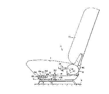
Figure 1 is a side elevational view of a
vehicle seat embodying the principles of the present
invention;
Figure 2 is a side elevational view of the
vertical adjusting mechanism embodied in the seat of
Figure 1, showing the actuating lever in a locking
position;
Figure 3 is a view similar to Figure 2
showing the actuating lever in a rearward releasing
position;
Figure 4 is a view similar to Figure 2
showing the actuating lever in a forward releasing
posltlon;
Figure 5 is a plan view of the power
operating assembly shown in Figure 1 with the bellows
element removed together with the top part of the
housing;
.
Figure 6 is a sectional view taken along the
line ~-6 of Figure 5 with the top part of the housing
in place;
Figure 7 is a sectional view similar to
Figure 6 taken along the line 7-7 of Figure 5;
CA 02243180 1998-07-1~
W O 97/26147 PCT~B97/00101
Figure 8 is an enlarged sectional view
similar to Figure 6 taken along the line 8-8 of Figure
5; and
Figure 9 is a perspective view of the
mounting assembly disclosed in United States Patent
No. 5,568,908 prior to the modification thereof in
accordance with the principles of the present
nvent lon .
D~:TAILED DESCRIPTION OF THE INVENTION
Referring now more particularly to the
drawings, there is shown in Figure 1 a vehicle seat 10
which embodies the principles of the present
invention. The vehicle seat 10 includes a seat
cushion assembly, generally indicated at 12, which can
embody any conventional construction and includes the
usual frame, cushioning and cover. The seat cushion
assembly 12 is mounted on a vehicle ~loor assembly 14
by a mounting assembly, generally indicated at 16.
The mounting assembly 16 em~odies therein a six-way
manual adjusting mechanism, generally indicated at 18,
which, as shown, is based on the disclosure of the
six-way manual adjusting mechanism contained in the
aforesaid U.S. Patent No. 5,568,908, but modified in
accordance with the principles of the present
invention. The seat 10 also includes a seat back
cushion assembly 20 which likewise may be of any
conventional construction including the usual frame,
cushioning and cover. The seat back cushion assembly
20 is mounted on the seat cushion assembly 12 by a
second mounting assembly, generally indicated at 22.
The mounting assembly 22 is shown somewhat
CA 02243180 1998-07-1~
W O 97/26147 PCT~B97/OOlOl
schematically in Figure 1 and includes an adjusting
mechanism, generally indicated at 24.
In the broadest aspects of the present
invention, the mounting assembly 16 can be based upon
any conventional mounting assembly of the prior art
which includes a manual adjusting mechanism. However,
a preferred mounting assembly in this regard is the
mounting assembly disclosed in the aforesaid U.S.
Patent No. 5,568,908 which embodies therein a six-way
manual adjusting mechanism. Figure 9 illustrates the
construction of the U.S. Patent No. 5,568,908 prior to
the modification thereof in accordance with the
principles of the present invention.
As shown in Figure 9, the mounting assembly
16 includes a six-way manual adjusting mechanism 18
which includes a fore and aft horizontal adjusting
mechani~sm, generally indicated at 26, and a front and
rear vertical adjusting mechanism, generally indicated
at 28. The horizontal adjusting mechanism 26 includes
left and right track assemblies 102 and 104. The
track assemblies 102 and 104 include elongated
stationary tracks 106 and 108, respectively, that are
~ixedly mounted on the vehicle floor 14, and elongated
translating tracks 110 and 112, respectively, that are
slidably interconnected with the stationary tracks 106
and 1~8. The horizontal adjusting mechanism 26 is
provided to allow an occupant of the seat to
selectively position the translating tracks 110 and
112 and hence the cushion assemblies 12 and 20 of the
seat 10 in any one adjusted position within a range of
horizontal positions relative to the stationary tracks
106 and 108.
CA 02243180 1998-07-1~
W O g7126147 PCTnB97100101
The horizontal ad~usting mechanism 26
includes a locking and releasing device 118 embodying
an actuating member in the form of a U-shaped bail
114, the legs of which are pivotally mounted by pins
116 to the translating tracks 110 and 112,
respectively. The actuating member ls normally ~pring
biased lnto a locking position by biasing spring
mem~er 119 as shown in Figure 9. The bight portion of
the U-shaped bail 114 is positioned below the forward
end of the seat cushion assembly 12 so that a seat
occupant can selectively disengage the locking and
releasing device 118 by lifting the adjusting bail
114. With the locking and releasing device 118
disengaged, the translating tracks 110 and 112 are
slidable relative to the stationary tracks 106 and 108
and the occupant of the seat may m~nl~lly position the
seat 10, which is fixed to the translating tracks 110
and 112, in a selected one o~ a multiplicity of
different horizontal positions in a fore and aft
direction. Upon release of the adjusting bail 114,
biasing spring members 119 within the locking and
releasing device 118 will urge the locking and
releasing device 118 back into a locked position. The
details of construction of the locking and releasing
device may include any known prior art constructions
such as that disclosed in U.S. Patent 4,733,845. In
one embodiment, both fore and aft movements are
accomplished manually by the operator or seat
occupant. It is within the contemplation o the
present invention that the seat could be moved by
springs in one direction under the control of the
operator and manually moved in the other against the
spring bias provided.
11
CA 02243180 1998-07-l~
W O 97/26147 PCT~B97/OOlOl
The vertical adjusting mechanism 28 aspect
of the mounting assembly 16 includes forward and
rearward seat support arm assemblies 203 and 205, each
including a ~orward torsion rod 202 and a rearward
torsion rod 206, respectively. As shown in Figure 9,
mounted on opposite ends o~ the ~orward torsion rod
202 are le~t and right ~orward seat support arms 222
and 226, respectively. The ~orward seat support arms
222 and 226 are fixedly mounted to the ~orward torsion
rod 202 so as to be rotatable along with the forward
rod 202, the left forward seat support arm 222 being
a slave o~ the right ~orward seat support arm 226, and
vice versa.
Mounted on opposite ends o~ the rearward
torsion rod 206 are left and right rearward seat
support arms 230 and 234, respectively. The rearward
seat support arms 230 and rod 234 are ~ixedly mounted
to the rearward torsion rod 206 so as to be rotatable
with the rearward rod 206, the le~t rearward seat
support arm 230 being a slave o~ the right rearward
seat support arm 234, and vice versa. In addition, as
shown in Figure 9, the rearward torsion rod i~
operatively coupled with a spring biasing system 238
which urges the rearward torsion rod 206 to rotate in
such a manner as to rotate the rearward seat support
arms 230 and 234 into an upward position.
Le~t and right seat cushion mounting members
244 and 250 are provided for securing the vehicle seat
10 to the six-way seat adjustment assembly 18. The
end portions 224 and 228 o~ the le~t and right ~orward
seat support arms 222 and 226, respectively, are
pivotally coupled with the ~orward portions 246 and
252 o~ the le~t and right seat cushion mounting
12
CA 02243180 1998-07-1~
W O 97126147 PCTn~97/OOlOl
members 244 and 250, respectively. The forward seat
support arms 222 and 226 are coupled with the seat
cushion mounting members 244 and 250 by means o~ pins
256 and 258, respectively, extending from the forward
pivoting seat support arms 222 and 226 and into
longitudinal slots 260 and 262 (see Figure 9) in the
forward portions 246 and 252 of the seat cushion
mounting members 244 and 250, thus effecting a lost
motion coupling. Also, the end portions 236 o~ the
left and right rearward seat support arms 230 and 234
are pivotally attached to the rearward portions 248
and 254 of the le~t and right seat cushion mounting
member 244 and 250 respectively. The seat 10,
including the seat cushion assembly 12 and the seat
back cushion acsembly 20 carried thereby, is mounted
to the seat cushion mounting members 244 and 250 by
any suitable means such as bolts or rivets.
A mounting structure is provided, which
includes le~t and right rod mounting members 210 and
212 and component mountlng structure 214. The torsion
rods 202 and 212 and a component mounting structure
214. The torsion rods 2Q2 and 206 are journally
supported in a parallel arrangement by the left and
right rod mounting members 210 and 212. Furthermore,
the left and right rod mounting members support the
forward and rearward seat support arm assemblies 203
and 205 and the seat assemblies 12 and 20 supported
thereon on the translating tracks 110 and 112 to allow
the seat assemblies 12 and 20 and the translating
tracks to be positioned horizontally relative to the
stationary tracks 106 and 108. The seat support arm
- assemblies are fixed to the translating tracks by any
suitable means, such as bolts, rivets, welds, or the
13
CA 02243180 1998-07-1~
W O 97/26147 PCT~B97/00101
like. In this manner, the vehicle seat assemblies 12
and 20 are secured to the vehicle floor 14.
As shown in Figures 2-4 and 9, the vertical
adjusting mechanism allows the occupant of the seat to
independently position either the forward or rearward
seat support assemblies 203 and 205 into a selected
one of a multiplicity of vertical positions and then
retain the seat support assembly thereat.
The vertical adjusting mechanism 28 includes
the component mounting structure 214 that is arranged
adjacent to and parallel with one of the track
assemblies. The component mounting structure 214 is
shown in Figure 9 positioned adjacent to and parallel
with the left track assembly 102; however, it will be
clear tjo one skilled in the art that the component
mounting structure may be fixed alongside the right
track assembly 104 as well. The component mounting
structure 214 is constructed of an inner component
mounting structure plate 216 and an outer component
mounting structure plate 218, disposed in
substantially parallel arrangement and defining a
space 220 therebetween.
As best shown in Figures 2-4, the vertical
adjusting mechanism 28 includes a locking and
releasing device, generally indicated at 263,
constructed and arranged to be moved between (1) a
locking position wherein the locking and releasing
device 263 is operable to lock the vertical adjusting
mechanism 28 to prevent generally vertical movement of
the forward and rearward portions of the seat cushion
assembly 12 in either direction, (2) a first releasing
position wherein the locking and releasing device 263
14
CA 02243180 1998-07-1~
W O 97126147 PCT~B97100101
is operable to release the vertical adjusting
mechanism 28 to permit the forward portion of the seat
cushion assembly 12 to ~e manually moved generally
vertically in one direction and returned in the
opposite direction while the rearward portion of the
seat cushion assembly 12 is locked against generally
vertical movement in either direction, and ~3) a
second releasing position wherein the locking and
releasing device 263 is operable to release the
vertical adjusting mechanism 28 to permit the rearward
portion o~ the seat cushion assembly 12 to be manually
moved generally vertically in one direction and
returned in the opposite direction while the forward
portion o~ the seat cushion assembly 12 is locked
against generally vertical movement in either
direction.
The locking and releasing device 263
includes a forward sector gear 264 ha~ing locking
projections 266 along a curved portion thereof is
mounted on the forward torsion rod 202 in the space
220 between the inner and outer component mounting
structure plates 216, 218. The forward sector gear
264 is fixedly mounted to the forward torsion rod 202
so as to be rotatable with the rod and is oriented in
2~ such a manner that the locking projections 266
general~y face rearwardly. The range of rotational
motion of the forward sector gear 264, and thus of the
forward torsion rod 202, is preferably restricted by
means of a restraining pin 268 extending from the
forward sector gear 264 and into a forward arcuate
slot 270 located in the component mounting structure
214.
CA 02243l80 l998-07-l~
W O 97/26147 PCT~B97/00101
.
In a mirror construction of the forward
sector gear 264, a rearward sector gear 274 having
locking projections 276 along a curved portion thereof
is mounted on the rearward torsion rod 206 in the
space 220 between the inner and outer component
mounting structure plates 216 and 218. The rearward
sector gear 274 is fixedly mounted to the rearward
torsion rod 206 so as to be rotatable with the rod and
is oriented in such a manner that the locking
projections 276 generally face forwardly. The range
of rotational motion of the rearward sector gear 274,
and thus of the rearward torsion rod 206, is
preferably restricted by means of a restraining pin
278 extending from the rearward sector gear 274 and
in~o a rearward arcuate slot 280 located in the
component mounting structure 214.
At a position toward the center of the
component mounting structure 214 from the forward
sector gear 264, a forward locking member 282 (gee
Figures 2-4) having locking teeth 284, an engaging
surface 286, and a disengaging surface 288 is
pivotally mounted on a pin 290 in the space 220
between the inner and outer component mounting
structure plates 216 and 218. The forward locking
member 282 iS pivotable between ~1) an engaged
positicn, shown in Figures 2 and 4, wherein the
locking teeth 284 are engaged with the locking
projections 266 of the forward sector gear 264 thereby
preventing rotation of the forward sector gear, the
forward seat support arm assembly, and the forward
portion of the seat cushion assern~ly, and (2) a
disengaged position, shown in Figure 3, wherein the
locking teeth 284 are disengaged from the locking
projections 266 of the forward sector gear 264,
16
CA 02243l80 l998-07-l~
W O 97/26147 PCTnB97/OOlOl
thereby releasing the forward sector gear 264, the
forward seat support arm assembly 203, and the forward
portion of the seat cushion assembly for vertical
t positioning of the forward portion of the seat cushion
assembly.
In a mirror construction of the forward
locking member 282, at a position toward the center of
the component mounting structure 214 from the rearward
sector gear 274, a rearward locking member 292 having
10 locking teeth 294, an engaging sur~ace 296, and a
disengaging surface 298 is pivotally mounted on a pin
300 in the space 220 between the inner and outer
component mounting structure plates 216 and 218. The
rearward locking member 292 is pivotable between (2)
an engaged position, shown in Figures 2 and 3, wherein
the locking teeth 294 are engaged with the locking
projections 276 of the rearward sector gear 274
thereby preventing rotation of the rearward sector
gear, the rearward seat support arm assembly, and the
rearward portion of the seat cushion assembly, and (2)
a disengaged position, shown in Figure 4, wherein the
locking teeth 294 are disengaged from the locking
projections 276 of the rearward sector gear 274,
thereby releasing the rearward sector gear 274, the
rearward seat support arm assembly 205, and the
rearward portion of the seat cushion assembly for
vertical positioning of the rearward portion of the
seat cushion assembly.
At a position toward the center of the
component mounting structure 214 ~rom the forward
locking member 282, a forward camming member 302
having a locking sur~ace 304 and a camming surface 306
is pivotally mounted on a pin 3~8 in the space 220
17
CA 02243l80 l998-07-l~
W O97/26147 PCT~B97/00101
between the inner and outer component mounting
structure plates 216 and 218. The forward c~mm; ng
member 302 i8 mounted ~or pivotal movement between (1)
a locked position, shown in Figures 2 and 4, wherein
the locking surface 304 iS engaged with the engaging
surface 286 of the forward locking member 282 so as to
urge the forward locking member into its engaged
position, and (2) a released position, shown in Figure
3, wherein the camming surface 306 is engaged with the
disengaging surface 288 of the forward locking member
282 so as to urge the forward locking member into its
disengaged position.
In a mirror construction of the forward
~ mm; ng member 302, at a position toward the center of
the component mounting structure 214 from the rearward
locking member 292, a rearward camming member 312,
having a locking surface 314 and a camming surface
316, iS pivotally mounted on a pin 318 in the space
220 between the inner and outer component mounting
structure plates 216 and 218. The rearward camming
member 312 iS mounted for pivotal movement between (1)
a locked position, shown in Figures 2 and 3, wherein
the locking surface 314 is engaged with the engaging
surface 296 of the rearward locking member 292 so as
to urge the rearward locking member into its engaged
position, and (2) a released position, shown in Figure
4, wherein the camming surface 316 iS engaged with the
disengaging surface 298 of the rearward locking member
292 so as to urge the rearward locking member into its
disengaged position.
The vertical adjustment mechanism 28 is
~urther provided with a resilient coupling 322, such
as a tension spring or the like, disposed within a
~ 18
CA 02243l80 l998-07-l~
W O97/~6147 PCT~B97/OOlOl
horizontal slot 324 in the component mounting
structure 214. Opposite ends of the resilient
coupling 322 are attached to lower portions 326 and
336 of the forward and rearward camming members 302
and 312 so that the resilient coupling urges the
forward and rearward camming members into their locked
positions.
An actuating member 338 is pivotally mounted
at 340 to the component mounting structure 214
generally at its center. The lever actuated control
member is movable between a centered locking position,
see Figure 2, and either a first releasing position,
see Figure 4, or a second releasing position, see
Figure 3.
As can be seen in Figure 2, the actuating
member 338 defines a line of symmetry about which the
geometry of the components mounted to the forward
portion of the component mounting structure mirrors
the geometry of the components mounted to the rearward
portion of the component mounting structure.
A fore and aft motion transmitting member
342 having a forward longitudinal slot 344 and a
rearward longitudinal slot 346 iS coupled with the
actuating member 338 at an end of the actuating member
opposite the end at which it is pivotally mounted to
the component mounting structure 214. The fore and
aft motion transmitting member 342 iS coupled with the
actuating member 338 preferably by means of a lost
motion coupling formed by a pin 348 extending from the
lever actuated control member and into a transversely
elongated hole 350 located in the fore and aft motion
transmitting member 342 between the forward
19
CA 02243180 1998-07-1~
W O97/26147 PCTA~97/0~101
.
longitudinal slot 344 and the rearward longitudinal
slot 346.
A forward camming member sliding pin 310
extending from the ~orward camming member 302 and into
5 the forward longitudinal slot 344 couples the ~ore and
aft motion transmitting member 342 with the forward
camming member 302. Similarly, a rearward camming
member sliding pin 320 extending from the rearward
camming member 312 and into the rearward longitudinal
slot 346 couples the fore and aft motion transmitting
member 342 with the rearward camming member 312.
A manually engageable lever 352 is ~ixedly
attached at 354 to the actuating member 338 such that
the manually engageable lever 352 forms a portion of
t~e actuating member 338 that pivots about point 340.
The manually engageable lever enables an occupant of
the seat to manually move the actuating member 338
from the centered locking position into a selected one
of the releasing positions.
In accordance with the principles of the
present invention, the components of the vertical
adjusting mechanism 28 described above has added
thereto a power operated assembly, generally indicated
at 410, which is constructed and arranged to enable
25 the locking and releasing device 263 to be moved
between the locking and the first and second releasing
positions thereof. In addition, there is provided a
manually operated remote control, generally indicated
at 412, which is constructed and arranged to operate
30 the power operated assembly 410 to enable the locking
and releasing device 263 to be selectively moved
CA 02243180 1998-07-1~
W O 97/2.6147 PCT~B97/00101
between the locking and the first and second releasing
positions thereo~.
As best shown in Figures 5-8, the power
operated assembly 410 includes a housing ~ormed by two
cooperating housing parts 414 and 416 which are
connected together by suitable ~asteners. Mounted
within the housing parts 414 and 416 is an electric
motor 418 having an output shaft 420. As best shown
in Figures 5-7, mounted on the output sha~t 420 is a
centrifugal coupler, generally indicated at 422. The
centrifugal coupler 422 includes a housing member 424
which is suitably fixed to the output sha~t 420.
Mounted within the housing members 424 is a pair of
weights 426 Each of the weights 426 is in the ~orm
of a disk having a central cylindrical projection
extending from the center thereof. Each weight 426 is
mounted within the housing member 424 to be spring
biased, as by a coil spring 428, into a decoupling
position within the housing member 424. When the
output shaft 420 is rotated, the weights 426 are moved
by centri~ugal ~orce generally radially outwardly
against the bias of springs 428 into a coupling
posltlon.
The centrifugal coupler 422 also includes a
driven member 430 which is rotatably mounted on the
output shaft 420 and has affixed thereto a driving
portion 432 in the form of a rod which includes a bent
central portion with arcuate ends embracing the driven
member 430 in fixed relation. The driven portion 432
is disposed in a position to avoid engagement by the
weights 426 when in the decoupling position thereo~
and to be engaged by either one of the weights
426 when in the coupling position thereof.
21
CA 02243l80 l998-07-l~
W O 97/26147 PCT~B97/O~lOl
Fixed to the driven member 130 iS a small
spur gear 434 which, in turn, meshes with a large spur
gear 436 fixed to a second shaft 438 disposed parallel
with the output shaft 420 of the electric motor 418.
As best shown in Figures 5 and 6, the ends of the
second shafk 438 are journalled between the housing
parts 414 and 416 and a portion of the second shaft
438 which extends between the large spur gear 436 and
the ad3acent end thereof is ~ormed with a series of
large pitch threads 440 on the exterior periphery
thereof. A moving member 442 includes an inner
portion 444 which is mounted within the housing parts
414 and 416 for longitudinal translational movement in
opposite directions. The inner portion 444 is
internally threaded to me5hingly engage with the
series off large pitch threads on the second shaf~ 438
80 that, when the second shaft 438 iS rotated in one
direction, the moving member 442 will be moved in one
direction and, when the second shaft is rotated in the
opposite direction, the moving member 442 will be
moved in the opposite direction.
The moving member 442 includes an outer
portion which is apertured, as indicated at 446, and,
as shown in Figures 2, 3 and 4, a flexible bellows
~5 shaped boot 448 iS mounted on the moving member 442 SO
as to cover the portion of the moving member 442 which
is exterior of the housing parts 414 and 416. The
outer end of the moving member 442 iS connected to the
actuating member by a pin 450 which also extends
through aligned slots in an offset end extension of
the manually engageable lever 352 and the actuating
member 338.
,
CA 02243180 1998-07-1~
W O97/26147 PCT~B97/00101
~ eferring now more particularly to Figure 1,
the manually actuated remote control 412 includes a
housing 452 containing a first spring pressed button
or switch which is electrically connected with a
source of electricity (e.g., the vehicle battery) and
with the electric motor 418 in such a way as to cause
rotation of the output shaft 420 of the electric motor
418 in one direction when the button 454 is pushed and
held manually. The remote control 412 also includes
a second spring pres9ed button or switch 456 which is
connected electrically with a source of electricity
and the electric motor 418 in such a way as to cause
the output shaft 420 to rotate in the opposite
direction.
The arrangement is such that, when an
operator manually pushes the button 454, the electric
motor 418 will be energized to cause the output sha~t
420 to rotate in one direction. As soon as the output
shaft 420 begins to rotate, the weights 426 will be
moved from their spring pressed decoupling position in
a generally radially outward direction into their
coupling position by centrifugal force. As soon as
the weights 426 reach the coupling position, one of
the weights 426 will engage the driving portion 432 of
the driven member 430 to cause the small spur gear 434
to rotate with the output shaft 420. The meshing of
the small spur gear 420 with the large spur gear
causes the second shaft 438 to rotate about its axis.
The rotation of the second shaft 438 enables threads
440 to move the moving member 442 and the actuating
member 338 therewith from a central locking position
into a first releasing position as shown in Figure 3.
In this position, the actuating member 338 is operable
to move the locking member 282 out of engagement with
23
CA 02243180 1998-07-1~
W O97/~147 PCT~B97/00101
the sector 264 thereby allowing the seat occupant to
adjust the forward portion of the seat cushion
assembly 12 into a desired adjusted position within
the range of vertical adjusted positions provided.
S The movement of the seat 10 is by a manual movement of
the seat occupant either leaning forward to move the c
forward portion of the seat cushion assembly 12
downwardly or leaning backward against the seat back
cushion assembly 20 to pivot the forward end of the
lO seat cushion assembly 12 upwardly. During the
adjusting movement by the seat occupant, the continued
energization of the electric motor 418 is required in
order to maintain the actuating member 338 in its
first releasing position. As soon as the forward
15 portion of the seat cushion assembly 12 has been moved
into its desired adjusted position, the seat occupant
releases the button 454 which releases the bias of the
electric motor 418 to maintain the centrifugal coupler
422 in its coupling position. As soon as the electric
motor 418 is released, the spring bias 428 of the
weights 426 will return the weights 426 to their
decoupling position, thus decoupling the motion
transmitting mechanism between the output shaft 420
and the movable member 446. This allows the actuating
member 338 to be returned to its locking position
under the bias of spring 322.
When the button 456 is pressed by the
operator, the electric motor 418 will be energized to
rotate the output shaft 420 in the opposite direction.
As soon as the outpu~ shaft 420 begins to rotate, the
centrifugal coupler 422 will be moved from its
decoupling position to its coupling position to drive
the small gear 434 which, in turn, rotates the second
shaft 438. The meshing threads 440 cause the moving
24
CA 02243180 1998-07-1~
W O 97/26147 PCT~B97/00101
.
member 442 to be moved forwardly, which, in turn,
moves the actuating member 338 into its second
releasing position. In this position, the locking
member 192 is moved so that its teeth 294 are out of
engagement with the teeth 276 of the member 274, thus
enabling the rear portion of the seat cushion assembly
12 to be moved upwardly by the spring system 205 under
the control of th~ seat occupant or, alternatively,
enabling the operator to move the rear portion of the
seat cushion assembly 12 downwardly by leaning against
the seat back cushion assembly 20 and causing the rear
portion of the seat cushion assembly 12 to pivot
downwardly against the action of the spring system
205. Here again, the operator should continue the
engagement of the button 456 until the adjustment has
been manually effected in order that the energization
o~ the electric motor 418 will maintain the
centri~ugal coupler 422 in its coupling position. As
soon as the button 456 is released, the energization
of the electric motor 418 iS released allowing the
centri:Eugal coupler 422 to move into its decoupling
position and enabling the actuating member 338 to be
returned to its locking position by the spring 322.
The remote control 412 iS shown in Figure 1
2 5 as being mounted on the side of the seat cushion
assembly 12. It will be understood that the remote
control 412 can be mounted on the dashboard or on the
console unit which is adjacent to the seat 10 or any
other desired place which is convenient to the seat
occupant.
~ While the provision o~ the power operated
assembly 410 and cooperating remote control 412 are
disclosed above as being particularly useful in
CA 02243180 1998-07-1~
WO 97/~Ç147 PCT~B97/OOlOl
conjunction with the dual vertical adjusting
mechanism, it will be understood that it is within the
contemplation of the present invention to combine the
power operated assembly 410 and cooperating remote
control 412 with any other known adjusting mechanism
as well as other known vertical adjusting mechanisms.
Moreover, it is wlthin the contemplation o~ the
present invention to combine the power operated
assembly 410 and the cooperating remote control 412
with each adjusting mechanism of a seat containing a
number of different adjustments for the entire seat
and/or the seat back assembly 20 of the seat. As
shown in Figure 1, the horizontal adjusting mechanism
26 has a second power operated assembly 410, connected
between the frame of the seat cushion assembly 12 and
the actuating member 114 thereof. A button 458 is
embodied in the remote control 412 to enable the seat
occupan~t to release the horizontal adjusting mechanism
26 and move the seat cushion assembly 12 into any
desired adjusted position within the range provided.
In addition, a third power operated assembly
410 is provided between a frame structure 460 o~ the
mounting assembly 22 and an actuating member 462 of
the adjusting mechanism 24 in the mounting assembly
22. The adjusting mechanism 24 is such that, when the
actuating member 462 is moved from the spring biased
locking position, shown in Figure 1, into a releasing
position, the seat back cushion assembly 20 can be
manually moved about a ~irst axis into any desired
adjusted included position within a range of inclined
positions provided or it may be moved ~orwardly about
a second axis into a dumped position within a range of
dumped positions all of which are essentially the same
or nearly the same. As before, in order to provide
26
CA 02243180 1998-07-l~
W O 97/26147 PCT~B97/00101
the operator with the ability to manually actuate the
third power operated assembly 410, the remote control
412 includes a button 464 which is electrically
connected to energize the electric motor 418 of the
power operated assembly 410 as before.
It will be noted that, in every instance,
the operation of the power operated assembly 410 is
such that the operator has the option of (l) directly
m~n1~lly moving the actuating member provided or (2)
lo manually depre6s the associated button o~ the remote
control 412 in order to enable a manual adjustment to
be accomplished. It will be understood that, while
this option is pre~erable, it is within the
contemplation of the present invention to provide
remote control operation only.
It thus will be seen that the objects o~
this invention have been fully and effectively
accomplished. It will be realized, however, that the
foregoing preferred specific embodiments have been
shown and described for the purpose of illustrating
the functional and structural principles of this
invention and is subject to change without departure
from such principles. Therefore, this invention
includes all modifications encompassed within the
spirit and scope of the following claims.