Note: Descriptions are shown in the official language in which they were submitted.
CA 02243490 1998-07-16
wo97n7377 PCT~S97/01220
FT-~TRT-~ GLASS RUN WITH RIGID MOLDED SUPPORT
BACKGROUND OF THE INVENTION
l. Field Of The Invention
This invention relates generally to a flexible
glass run for a vehicle door opening and, more
particularly, to a flexible glass run that is easily
secured to a vehicle door flange in the vehicle door
opening and includes molded plastic support members to
secure the glass run to a door trim panel below the belt
line of the door.
2. Discussion of the Related Art
Most vehicle doors include a door window that can
either be mechanically or electrically lowered into a door
well of the door to open a door opening, or raised from the
door well to close the door opening in a sealing manner.
These types of vehicle doors include a resilient glass run
having a glass run channel that the window seats within
when it is in a closed position. Different glass run
designs are known in the art that allow the window to be
repeatedly inserted within and removed from the glass run
channel and still maintain an effective seal against
environmental conditions such as wind and moisture. A door
belt line that includes a flexible sealing member extends
across the bottom of the door opening to allow the window
to slide through the belt line in a sealing manner as it is
being raised and lowered. Portions of both ends of the
glass run extend below the belt line of the door to guide
the window within the door well when it is in a lowered
position.
In modern designs, the glass run includes an
outer layer, such as an EPDM rubber, a thermoplastic
material or other suitable material, that is extruded onto
a rigid metal insert that gives the glass run support and
shape. Usually, the insert is a piece of stamped steel or
aluminum. The insert enables the glass run to be rigidly
secured to a flange extending from stamped door panels
along the periphery of the door opening. Because the
flange ends at the bottom of the door opening, there is no
flange which to secure the glass run to within the door
CA 02243490 1998-07-16
W O 97/27377 PCT~US97/01220
well. Therefore, brackets are generally provided that are
secured to the extended portions of the glass run by bolts
or the like. The brackets generally include a tab that
extends from the glass run that allows the bracket to be
secured to an appropriate area of a door trim panel within
the door well.
The abo~e described glass run has been generally
successful in meeting the demands required by the industry.
However, certain disad~antages of these types of glass runs
leaves room for improvement. For example, because known
glass runs are rigid members and are not readily flexible,
they must be stretch bent to the shape of the door opening
before being secured to the door flange. However,
inconsistencies in the alignment and position of the
flange, as well as the thickness of the flange, re~uire
that the glass run be further twisted and bent as it is
being secured to the door flange. Because the glas~ run is
rigid, such a process has obvious drawbacks when trying to
secure the glass run to the door flange. Also, the
resulting twisting nature of the glass run may alter the
sealing properties of the glass run channel in the glass
run.
Further, because a ~racket is needed to secure
the glass run to the door within the door well, the
cur~ature of the door and the size of the bracket prevents
the glass run from being installed to the door as a single
piece at the manufacturing level of the vehicle. The
rigidity of the brackets of both extended portions prevents
the extended portions of the glass run below the belt line
from being simultaneously inserted into the door well.
Therefore, at least one of the extended portions of the
glass run that fits within the door well must be mated to
the glass run when it is bolted to the door trim panel.
What is needed is a flexible glass run that can
be readily twisted to be secured to the door flange, and
includes a support member for supporting the glass run
within the door well that allows the glass run to be
connected to the door as a single unit. It is therefore an
CA 02243490 1998-07-16
W O 97/27377 PCTAJS97101220
object of the present invention to provide such a glass
run.
SUMMARY OF THE INVENTION
In accordance with the teaching of the present
invention, a flexible glass run is disclosed that is
readily connected to the flange of a vehicle door, and
includes plastic support members that are molded to
portions of the glass run that extend below the vehicle
belt line. In one embodiment, the glass run includes a
flexible semi-rigid insert that has been stamped and rolled
into a configuration such that a cross-section of the
insert includes two adjacent U-shaped portions and a tab
portion. An outer layer of a glass run material is
extruded onto the insert. A larger one of the U-shaped
lS portions is used to secure the glass run to a door flange.
The other U-shaped portion defines a channel that accepts
a connective insert to secure pieces of the glass run
together. The outer layer defines a glass run channel that
accepts a vehicle window in a sealing. The molded plastic
support members are curved such that the glass run can be
assembled as a single unit prior to being attached to the
vehicle door. Brackets are attached to the glass run and
secured to the vehicle trim panel.
Additional objects, advantages, features of the
present invention will become apparent from the following
description and appended claims taken in conjunction with
the accompanying drawings.
BRIEF DESCRIPTION OF THE DRAWINGS
Figure 1 is an outside perspective view of a
vehicle door;
Figure 2 is an outside view of a glass run
according to an embodiment of the present invention;
Figure 3 is a cross-sectional view of the glass
run of the invention as attached to the header of a vehicle
door;
CA 02243490 1998-07-16
W 097/27377 PCTAUSg7/01220
Figure 4 is a cross-sectional view of the glass
run of the invention within the door well of the vehicle
door along line 4-4 of Figure 2;
Figure 5 is a side view of a portion of the glass
run of the invention below the belt line of the vehicle;
Figure 6 is a cross-sectional view of the glass
run of the invention within the door well of the vehicle
door along line 6-6 of Figure 2;
Figure 7 is a cross-sectional view of an
alternate embodiment of the glass run of the invention
within the door well of the vehicle door; and
Figure 8 is a perspective view of an aluminum
insert within the glass run of the invention.
DETAILED DESCRIPTION OF THE PREFERRED EMBODIMENTS
The following discussion of the preferred
embodiments directed to a glass run for a vehicle door is
merely exemplary in nature and is in no way intended to
limit the invention or its applications or uses.
To help illustrate the glass run of the present
invention, Figure 1 shows an outside perspective view of a
vehicle door 10 for a vehicle (not shown). The vehicle
door 10 includes a stamped outer door panel 12 and a
stamped inner door trim panel 14. The door 10 is shown
partially broken away to 5how a door well 16 defined
between the outer door panel 12 and the trim panel 14. The
outer door panel 12 and the inner door trim panel 14 are
secured together by bolts, welds, and the like in a manner
that is well understood to one skilled in the art. The
outer door panel 12 and the inner door trim panel 14 are
stamped to include a window frame 18 that defines a door
opening 20 that is closed by a door window 22. The window
22 can be raised and lowered from the door opening 20 by an
applicable mechanism (not shown) positioned within the door
well 16. The window frame 18 is separated into an A-pillar
frame member 24 that is to be positioned adjacent to the A-
pillar (not shown) of the vehicle, a header frame member 26
that runs along the roof (not shown) of the vehicle, and a
CA 02243490 1998-07-16
W O 97/27377 rCTAUS97/01220
B-pillar frame member 28 that is to be positioned adjacent
to the B-pillar (not shown) of the vehicle when the vehicle
door 10 is in a closed position. A belt line sealing
member 30 is positioned at the bottom of the window frame
18 to allow the window 22 to be lowered into the door well
16 in a sealing manner.
A glass run 32, according to an embodiment of the
present invention, is secured to the window frame 18 around
the periphery of the opening 20, and includes end portions
that extend into the door well 16 below the belt line
sealing member 30. An outer side view of the glass run 32
removed from the door 10 is shown in Figure 2. The glass
run 32 is separated into three sections including a front
section 34 that runs along the A-pillar frame member 24 and
into a front portion of the door well 16, a header section
36 that runs along the header frame member 26, and a back
section 38 that runs along the B-pillar frame member 28 and
into a back portion of the door well 16. Prior to the
glass run 32 being connected to the door 10, the sections
34-38 are cut to the appropriate length. A connective
insert 40 is inserted into one end of the front section 34
and one end of the header section 36, and a connective
insert 42 is inserted into an opposite end of the header
section 36 and an end of the back section 38. The joined
ends of the header section 36 and the front section 34, and
the joined ends of the header section 36 and the back
section 38 are then placed in a mold (not shown) along with
a joining material to form a joint area 44 between the
front section 34 and the header section 36, and a joint
area 46 between the header section 36 and the back section
38.
The discussion below will describe the glass run
32 as including an extruded outer layer of a rubber
material. However, as will be appreciated by those skilled
in the art, this is by way of a non-~imiting example in
that the glass run can be made of any suitable material for
the purposes described herein. These materials include,
for example, natural and synthetic rubbers, thermoplastics,
CA 02243490 1998-07-16
W 097/27377 PCTrUS97/01220
or thermoset plastics. Generally, an outer layer of the
glass run 32 is made of an extrudable material that is
extruded onto a semi-rigid insert made of a suitable
material, such as aluminum or steel. The joining material
would be the same material as the outer layer.
As will be discussed in greater detail below, the
glass run 32 is attached to a door flange extending from
the frame 18 around the door opening 20. The door flange
ends at the belt line member 30. However, as shown, a part
of the front section 34 and the back section 38 extend
below the belt line member 30 and into the door well 16 of
the vehicle door 10. Because the flange does not extend
beyond the belt line member 30, some mechanism needs to be
provided to secure the glass run 32 at these locations in
order to properly guide the window 22 when it is in the
lowered position.
In order to secure the front section 34 and the
back section 38 within the door well 16, the front section
34 iS provided with a molded plastic support member 48 and
the back section 38 iS provided with a molded plastic
support member 50. The back section support member 50 is
shown in the cut-away of Figure 1 within the door well 16,
and a broken-away portion of the front section 34 showing
the support member 48 iS shown in Figure 5. Prior to the
front section 34 and the back section 38 being attached to
the header section 36, the front section 34 and the back
section 38 are placed in an appropriate mold (not shown) to
mold the plastic support members 48 and 50 to the glass run
32. The front support member 48 includes retaining tabs 52
and the back support member 50 includes retaining tabs 54
so as to rigidly secure the support members 48 and 50 to
the front and back sections 34 and 38, respectively. A
bracket 56 is attached to the front section 34 and a
bracket 58 is attached to the back section 38 in a manner
that will be discussed below. As will be appreciated by
those skilled in the art, the brackets 56 and 58 can take
on many shapes and can be made of many suitable materials,
such as metal brackets or molded plastic brackets that are
CA 02243490 1998-07-16
W O 97/27377 PCTAUS97/01220
molded with the plastic support members 48 and 50. The
brackets 56 and 58 each include a bolt (not shown~ that
bolts the front and back sections 34 and 38, respectively,
to the door trim panel 14 to hold the glass run 32 in the
appropriate position in the door well 16. For a molded
plastic bracket, the bolts can be eliminated, and a snap-
end type fastener can be used with a properly designed door
trim panel. Note that the shape of the support members 48
and 50 are curved substantially the same as the curvature
of the door window 22.
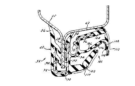
Figure 3 shows a cross-sectional view of the
glass run 32 through the header section 36 when the glass
run 32 is secured to the window frame 18 and the window 22
is in a down position. The cross-sectlon of the glass run
32 will be the same throughout all the sections 34-38 of
the glass run 32. A first stamped metal door section 60 is
secured to a second stamped metal door section 62 to define
a flange 64 as shown. In one embodiment, the door section
60 would be part of the trim panel 14 and the door section
62 would be part of the outer door panel 12. The door
sections 60 and 62 are secured together by known mechanism
such as welds.
The glass run 32 includes an outer rubber layer
68 extruded onto a metal insert 70. The shape of the metal
insert 70 and the outer rubber layer 68 is unique for the
purposes described herein. In one embodiment, the metal
insert 70 is defined by an aluminum sheet that has been
stamped and rolled to have the 5hape as shown in Figure 8.
Particularly, the metal insert 70 has been rolled to
include a larger square U-shaped portion 72 adjacent to a
smaller U-shaped portion 74, as shown. The U-shaped
portion 72 includes two legs attached substantially
perpendicular to a web that extends between the legs, and
the U-shaped portion 74 includes two legs attached to a
curved web. Note that one leg of the U-shaped portion 72
is aligned with one leg of the U-shaped portion 74. A tab
portion 76 extends from the top of the U-shaped portion 74
opposite from the U-shaped portion 72. An edge 78 extends
CA 02243490 1998-07-16
W097~7377 PCT~S97101220
into the U-shaped portion 74 proximate to the tab portion
76. A series of parallel elongated slots 80 have been
stamped and removed from the U-shaped portion 72, and a
series of slot~ 82 have been stamped and removed from the
U-shaped portion 74 and the tab portion 76 prior to the
insert 70 being rolled into the shape as shown. The slots
80 and 82 reduce the weight and increase the flexibility of
the metal insert 70 for the purposes described herein.
As mentioned above, the outer rubber layer 68 is
extruded onto the metal insert 70 by an applicable die (not
shown~ that gives the cross-sectional shape of the glass
run 32 as shown in Figure 3. The rubber layer 68 is formed
around the U-shaped portion 72 such that a first extended
portion 86 and a second extended portion 88 extend from the
legs of the U-shaped portion 72, as shown. Further, a
plurality of sealing lips 90 and a plurality of sealing
edges 92 are formed on the inside of the U-shaped portion
72. The glass run 32 is attached to the door 10 by forcing
the flange 64 within the U-shaped portion 72 such that the
sealing lips 90 are forced against the door section 60 that
makes up the flange 64, and the sealing edges 92 are forced
against the door section 62 that makes up the flange 64, as
shown. The extended portion 88 contacts the door section
60 and the extended portion 88 contacts the door section
62. Because the insert 70 and the rubber layer 68 are
sufficiently rigid, the flange 64 is held in place by the
sealing lips 90 and the sealing edges 92 in a secure
manner.
The extruding process does not form a portion of
the rubber layer 68 within the U-shaped portion 74 of the
metal insert 70. The internal shape of the U-shaped
portion 74 and the edge 78 allows the connective in~erts 40
and 42 to be inserted into this opening and rigidly secured
there to form the joint areas 44 and 46 as discussed above.
Previous glass runs were extruded to provide an opening to
accept these types of connective inserts in a rubber lined
channel. By utilizing the channel formed by the U-shaped
portion 74 and the edge 78 to accept the connective inserts
CA 02243490 1998-07-16
W O 97/27377 PCTAUS97/01220
40 and 42, the integrity of the joint areas 44 and 46 can
be increased over these prior art glass runs.
The glass run 32 includes a glass run channel
100. The glass run channel 100 is defined by a first
finger member 102 that extends from the web or base area of
the U-shaped portion 72. A portion 104 of the rubber layer
68 extends from the tab 76 and a portion 106 of the layer
68 extends from the web or base area of the U-shaped
portion 74. The portion 104 and the portion 106 both join
to a second finger member 108, as shown. A flocking layer
110 is secured to one surface of the finger member 102, a
flocking layer 112 is secured to one surface of the second
finger member 108, and a flocking layer 114 is secured to
an opposite surface of the second finger member 108, as
shown. The glass run 32 is shown in its relaxed state in
Figure 3. The flocking layers 110 and 112 ride against an
edge of the window 22 when the window 22 is inserted into
the glass run channel 100, in the manner that will be
discussed below with reference to Figure 4. A plastic
strip 116 positioned within the glass run channel 100 on
the portion 106 contacts the window when the window is
inserted in the glass run channel 100 so as to reduce wear
on the glass run 32.
Figure 4 shows a cross-sectional view of the
glass run 32 through line 4-4 of Figure 2. As is apparent
from this view, the window 22 is in a down location such
that the window 22 is positioned within the glass run
channel 100. When the window 22 is inserted into the glass
run channel 100 at this location, or when the window is in
an up location in the glass run channel 100, the window 22
first contacts the flocking layer 110 and forces the finger
member 102 upwards and away from the glass run channel 100.
As the window 22 continues to travel into the glass run
channel 100, the window 22 contacts the plastic strip 116
and forces the section 106 to travel towards the section
104. As the section 106 is pushed towards the section 104,
the second finger 108 curves inward and upward and the
flocking layer 112 contacts the window 22, as shown. Such
CA 02243490 1998-07-16
W O 97n7377 PCTrUS97/01220
-- 10
a relationship seals the window 22 in the glass run channel
100 .
The cross-section of Figure 4 is through the tab
52 of the support member 48. Therefore, the tab 52 is
shown following the contours of the rubber layer 68 as this
location of the glass run 32. Note that at this location,
the glass run 32 will not be connected to the flange 64.
Therefore, plastic is formed within the U-shaped portion 74
to help form the curvature of the door window 22 within the
support member 48.
Figure 6 shows a cross-sectional view of the
glass run 32 through line 6-6 of Figure 2. This view shows
the support member 48 being molded to the glass run 32 and
the bracket 56 being secured to the glass run 32. As is
apparent, the support member 48 is molded to the glass run
32 in a manner that will cause the support member 48 to be
rigidly secured to the glass run 32. The bracket 56
includes a tab section 120 that is inserted within the U-
shaped portion 72 to contact the lips 90 and the edges 92
in the same manner as the flange 64. The bracket 56 also
includes a tab section 122 embedded within the support
member 48. To accomplish this, the bracket 56 is placed
within a mold along with the glass run 32 when the plastic
of the support member 48 is molded to the glass run 32.
Therefore, the bracket 56 is rigidly secured to the glass
run 32. The bracket 56 further includes an extended
section 124 that extends away from the glass run 32 to be
attached to a securing section 126. A bolt 128 extends
through the securing section 126 to be secured to the trim
panel 14 in a manner that is well understood in the art.
Figure 7 shows an alternate embodiment of a
bracket for securing the glass run 32 to the vehicle door
10 below the belt line. In this embodiment, a bracket 132
is simultaneously molded with a support member 134 such
that the bracket 132 and support member 134 are a single
unit. A suitable attachment mechanism 136 secures the
bracket 134 to the trim panel 14.
CA 02243490 1998-07-16
W 097~7377 PCTAUS97/01220
- 11 -
The foregoing discussion discloses and describes
merely exemplary embodiments of the present invention. One
skilled in the art will readily recognize from such
discusslon, and from the accompanying drawings and claims,
that various changes, modifications and variations can be
made therein without departing from the spirit and scope of
the invention as defined in the following claims.